1
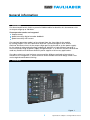
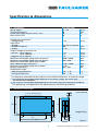
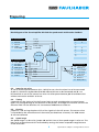
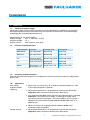
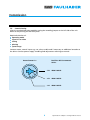
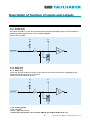
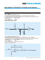
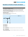
Servo Amplifier
4-Quadrant PWM for Brushless DC-Servomotors
Series BLD 7010
Operating Instructions
c om
w. fau
w
w
l
h
er.
b
a
Miniature Drive Systems
Micro Drives
DC-Micromotors
Precision Gearheads
Servo Components
Drive Electronics
Surf to the following Internet
address and you will find the
latest edition of the instruction
manual on-line :
www.minimotor.ch/uk/pr/
For direct Download:
http://www.minimotor.ch/minicatalog/pdf/DriveCircuits/Manuals/IM_e_BLD_7010.pdf
Index
Chapter
page
1.
Description
2
2.
Illustration
2
3.
Specification
3
4.
Dimensions
3
5.
5.1
5.2
5.3
5.4
5.5
5.6
5.7
5.8
5.9
Safety notes
Skilled personnel
Laws
Remove load
Additional safety components
Repair
Danger
Maximum input voltage
ESD
EMC
4
4
4
4
4
4
4
4
4
4
6.
6.1
6.2
6.3.
6.4.
6.5.
6.6.
Preparing
Operating mode
Connecting diagrams
Input for set value
Timing
Phasing
Speed range
5
5
5
6
6
6
6
7.
7.1.
7.2.
7.3.
7.4.
7.5.
Commission
Selection of power supply
Function of potentiometers
Presetting of potentiometers
Adjustment
Commissioning
7
7
7
7
7
8
8.
8.1.
8.2.
Description of function of inputs and outputs
Inputs
Outputs
9
9
11
9.
Troubleshooting
13
1
General information
1.
Description
The Servo Amplifier BLD 7010 is a powerful PWM-module for brushless DC-Servomotors with
an output range up to 700 Watt.
Three operation modes are integrated
Torque-control
Speed-control by digital-encoder feedback
Speed-control by Hall sensors
The required operation mode is to be selected from the front side of the module
by setting jumpers. This BLD 7010 servo amplifier is protected against over current
overheat and short-circuit of the output stage against each other or to the power supply.
By the usage of advanced technology and power- MOSFETs a high efficiency up to 95 %.
Due to the wide range of power supply voltage between 11 to 70 VDC the BLD 7010 can be
used very flexible with different kinds of power supplies within many applications.
The robust aluminum case has been constructed for different methods of mounting it,
therefor a fast integration is. Screw terminals and a durable controller-design allow a fast
and straightforward commissioning.
2.
Illustration
Figure 1
2
Specifications subject to change without notice
Specification & dimensions
3.
Specification
BLD 7010 SC4P
Power supply
Switching frequency
Continuous output current @ TA = 22°C
Peak current limit
Analog input command: 1)
– Voltage range
Logic input:
– Encoder
– Encoder frequency
– Enable
Output voltage for external use:
– Positive (max. 20 mA)
(max. 100 mA)
– Negative (max. 20 mA)
Maximum controllable speed with Hall Sensor 2)
Minimum controllable speed with Hall Sensor 3)
Maximum controllable speed with Encoder
(with 1 000 lines per revolution) 2)
Minimum controllable speed with Encoder 3)
External inductance 4)
Temperature range:
– Operating temperature
– Storage temperature
11 ÷ 70
49
10
20
V DC
kHz
A
A
± 10
V DC
TTL level A, B channel
100
8 - 30
kHz
V DC
+ 15
+5
- 15
5 000 / 40 000
250 / 2 000
V DC
V DC
V DC
rpm
rpm
1 250 / 10 000
5 / 40
100 ÷ 300
rpm
rpm
µH
–10 ... + 45
–40 ... + 80
°C
°C
1)
Analog input command may be set by an external potentiometer or an external voltage.
The maximum controllable speed depends on the power supply, the motor type,
the load and the feedback.
3)
The minimum controllable speed depends on the motor type, the load and the feedback.
4)
The appropriate value depends on the operating cycle and working conditions.
2)
4.
Dimensions and weight
2,8
1,4
4 x ø 4,5 Mounting hole
C
100
90
Scale reduced
B
82
A
Weight 650 g
20
10
140
12
12
6
24
40
170
3
Figure 2
Specifications subject to change without notice
Safety notes
5.
Safety notes
5.1
Skilled personnel
Installation and commissioning have to be done only by skilled personnel.
5.2
Laws
The user has to ensure the correct installation of the servo amplifier and additional
equipment according to valid laws and rules.
5.3
Remove load
For first commissioning the motor should run with free shaft which means without load.
5.4
Additional safety components
Electronic components are not free of failure or damage. Therefore plants have
to be installed with additional device and installation protecting components.
A safe and stable state has to be ensured in the case of damage of some devices, wrong
handling, cable disruption and other cases of any kind of malfunction.
5.5
Repair
Repairs have to be done only by authorized distributors or at the manufacturer. Unauthorized
opening and improper repairs of the device may cause danger to the user and the plant.
5.6
Danger
Care about having no power supply voltage all around the plant during installation of the
device. Never touch any voltage-carrying components.
5.7
Maximum input voltage
The input power supply voltage must not exceed 70 VDC. Voltages exceeding 70 V
or reversed connection will destroy the unit.
5.8
ESD
Do not touch any of the contacts of the device.
5.9
EMC
The BLD 7010 corresponds to the EC directives, standards and regulations 89/336/EWG article
10 and appendix 1 (EMV) amended by 92/31/EWG and 93/68/EWG and meet the requrements
with standard EN 61800-3 (1996) if the following directions are observed:
usage of a zinc plated mounting plate, well connected to earth
mounting of the drive by usage of toothed washers
usage of shielded cables to and from the unit
large area contact of the shielding with zinc plated mounting plate.
motor housing properly connected to earth
4
Specifications subject to change without notice
Preparing
6.
Preparing
Required selection of:
operating mode
input for set value
timing
phasing
speed range
6.1
Operating mode
Operating
mode
Torque control
Hall
Encoder
6.2
Jumper
setting
4
7; 8; 9
5; 6; 7
Active
potentiometers
Gain, nmax., Imax .Offset
Gain, nmax., Imax. Offset
Imax. Offset
Minimal connection
of control inputs
6; 9 - 13; 17; 18
6; 9 - 13; 17; 18
6 - 13; 17; 18
Connecting diagrams
Block diagram of the Servo Amplifier BLD 7010 for speed contol with Hall sensor feedback
or torque control
Pin Connector A
1
2
3
4
5
Motor A
Motor B
Motor C
+ VCC
Power GND
Jumper
brown
orange
yellow
+
–
Power supply
11-70 VDC
Brushless
DC-Servomotor
Pin Connector B
6
7
8
9
10
11
12
13
+ 5 V, 100 mA
Encoder A
Encoder B
GND signal
Hall sensor A
Hall sensor B
Hall sensor C
Enable
1
2
3
4
5
6
7
8
9
Torque control
Speed control
X
X
X
X
X
X
Pin Connector C
red
14
15
16
17
18
19
20
21
black
green
blue
grey
5
+ 15 V, 20 mA
GND signal
– 15 V, 20 mA
+ Set value
– Set value
Monitor n
Monitor I
Ready / Error
Specifications subject to change without notice
Preparing
Block diagram of the Servo Amplifier BLD 7010 for speed contol with Encoder feedback
Pin Connector A
1
2
3
4
5
Motor A
Motor B
Motor C
+ VCC
Power GND
Jumper
brown
orange
yellow
+
–
Power supply
11-70 VDC
Encoder
Brushless
DC-Servomotor
1
2
3
4
5
6
7
8
9
X
X
X
X
Pin Connector B
6 + 5 V, 100 mA
7 Encoder A
8 Encoder B
9 GND signal
10 Hall sensor A
11 Hall sensor B
12 Hall sensor C
13 Enable
Pin Connector C
14
15
16
17
18
19
20
21
green
blue
grey
black
red
+ 15 V, 20 mA
GND signal
– 15 V, 20 mA
+ Set value
– Set value
Monitor n
Monitor I
Ready / Error
6.3. Input for set value
at use of external potentiometer (min. 10 kΩ) for set value the wiper has to be connected
to pin 17, the others to pins 14 and 16. Pin 15 and 18 have to be connected and J3 is to
be removed. at use of the internal set value via offset potentiometer pin 15 and 18 are left
without connection and J3 is to be set.
6.4. Timing
jumper J2 sets the timing of the hall sensor logic to reach an adaptation to several motor
types. The setting belongs to the direction of the phases. J2 changes the rotation sense of the
electrical field. For the brushless DC- Servomotors 4490 J2 must to be set.
6.5. Phasing
jumper J1 is for setting the phase shift of the signals of the Hall sensors. The correct value
is to provide by the manufacturer of the motor (see datasheet of motor). For 4490 motors
J1 must be removed.
6.6. Speed range
the speed range is to be set by jumper J10 and J11. One of four speed ranges is to be set. The
best result of speed control can be reached by setting the lowest acceptable range because
of the resolution.
6
Specifications subject to change without notice
Commission
7.
Commission
7.1. Selection of power supply.
Any power supply can be used as long the minimal requirements listed below are fulfilled.
We recommend to remove the motor from the mechanical construction to avoid damage
and danger by uncontrolled movements of
Requirements to the power supply:
output voltage:
min. 11 VDC max. 70 VDC
residual voltage:
<5%
output current:
10 A nominal, 20 A peak
7.2.
Function of potentiometers
Potentiometer
Gain coarse
Function
gain adjustment
Turning CCW
decreasing
Turning CW
increasing
Gain fine
gain adjustment
decreasing
increasing
nmax.
maximum speed
at set value of 10 V
current limitation
decreasing speed increasing speed
Imax.
Offset
adjustment n = 0
at set value = 0
decreasing
min. 0,3 A
motor turns CW
increasing
max. 10 A
motor turns CCW
7.3. Presetting of potentiometers
Original delivered servo amplifiers are adjusted to uncritical values and for easy adjustment
by the user.
7.4.
Adjustment
Hall control
Digital-Encoderregelung
1. adjust max. set value ( e.g. 10 V ) and turn potentiometer nmax. CW
til the required speed is reached.
2. adjust potentiometer Imax. to required value of current limitation.
Important: Refer to motor manufacturer‘s data sheet.
3. turn potentiometer Gain slowly CW until the required gain is reached.
Important: If the motor turns rough, is vibrating or makes noise
turn potentiometer CCW again, until the instability of the system is
obsolete. The potentiometers Gain coarse and Gain fine work in an
additive way.
4. adjust set value = 0V and adjust potentiometer Offset until
the motor stops to speed 0.
Torque control
1. adjust potentiometer Imax. to required value of current limitation.
Important: Refer to motor manufacturer‘s data sheet.
7
Specifications subject to change without notice
Commission
7.5. Commissioning
select the required operating mode by setting the according jumpers on the left side of the unit.
Refer to the printing on the front plate.
Required selection of:
operating mode
input for set value
timing
phasing
speed range
Connect motor, control inputs e.g. set value, enable and if necessary an additional encoder to
the drive. Connect power supply. enabling and adjustment referring to manual.
Potentiometer Imax.
Brushless DC-Servomotors
Series:
8
~5A
4490 H 048 B
~6A
4490 H 036 B
~8A
4490 H 024 B
Specifications subject to change without notice
Description of function of inputs and outputs
8.
Description of function of inputs and outputs
In ( ) the pin number
8.1. Inputs
8.1.1 Set value (17, 18)
the input for set value is internally connected to an differential amplifier.
input range of set value:
-10 V...+10 V
input impedance:
20 kΩ
definition of polarity:
positive set value (+Set value) > (- Set value)
negative set value(+Set value) < (- Set value)
Input circuit set value:
11K
11K
11K
11K
– SOLL
+ SOLL
10nF
10nF
22K
8.1.2 Enable (13)
high potential at the input enable will activate speed/torque control and voltage will be
applied to the motor winding. Leaving this input without connection or pulling it tho GNDpotential will result in disabling the unit.
Input circuit enable:
+5V
2K2
2K2
ENABLE
1nF
390Ω
9
Specifications subject to change without notice
Description of function of inputs and outputs
8.1.3. Encoder A (7)
8.1.4. Encoder B (8)
the inputs encoder A, B are to be connected to the corresponding outputs of the encoder in
operating mode speed control with encoder feedback.
Input circuit encoder:
+5V
+5V
1K
1K
ENCODER
8.1.5. Hall A (10)
8.1.6. Hall B (11)
8.1.7. Hall C (12)
Inputs for the Hall effective sensors of the motor. The correct connection regarding phase
sequence and phase relation is essential
Input circuit hall effective sensors:
+5V
+5V
1K
1K
ENCODER
8.1.8. Power gnd (5)
8.1.9. +Vcc (4)
power supply connection.
Caution: do not connect: +Vcc or Power GND to the outputs Motor A, B, or C
10
Specifications subject to change without notice
Description of function of inputs and outputs
8.2. Outputs
8.2.1. Current monitor Monitor I (19)
a current monitor for supervisional purposes is integrated to the servo amplifier.
The output provides an analog signal (voltage) which is proportional to the motor current.
the monitor output is short circuit proof.
Output range:
-10 V... +10 V
Output impedance:
10 kΩ
Output proportionality: 0,5V/A
Output circuit current monitor:
+5V
+5V
1K
1K
ENCODER
8.2.2. Speed monitor Monitor n (20)
a speed monitor for supervisional purposes is integrated to the servo amplifier.
The output provides an analog signal (voltage) which is proportional to the motor speed.
It can be used for qualitative weighting of the dynamic of the drive system.
Output range:
-10 V... +10 V
Output impedance:
10 kΩ
Output proportionality: 10V at maximum speed
Output circuit speed monitor:
10K
MONITOR N
11
Specifications subject to change without notice
Description of function of inputs and outputs
8.2.3. Supervision signal Ready / Error (21)
The ready-signal is to show the status of the drive and can be used to provide a feedback
signal to other devices and controls. The open-collector output is normally turned off
which means the output is pulled to a positive level by an external connected resistor,
if there is no fault within the drive system.
In the case of a fault like under voltage, overvoltage, overheat or overcurrent the internal
transistor is on, the output is pulled to GND.
Input range max. 30 VDC
load current < 20 mA
any fault is stored and can be reset by enable off and on.
Output circuit ready/error signal:
ERROR
8.2.4. Motor C (3)
8.2.5. Motor B (2)
8.2.6. Motor A (1)
motor connection.
8.2.7. + 5 V, 100 mA (6)
auxiliary voltage source for power supply of hallsensors and/or incremental encoder
8.2.8. + 15 V 20 mA (14)
8.2.9. – 15 V 20 mA (16)
auxiliary voltage source for use as reference voltages by setting the set value by the means
of an external potentiometer
12
Specifications subject to change without notice
Troubleshooting
9.
Troubleshooting
Symptom
Operating mode Causes
power supply
motor does all
not turn
voltage < 11 V
Repair
check power supply
enable not
active
check level
at pin 14
set value = 0V
check set value
current limitation check potentiometer
adjusted too low adjustment Imax.
check potentiometer
adjustment nmax.
speed range
too low
wrong operation check jumper
setting
mode
no speed
control
bad connections
check connectors
wrong wiring
check wiring
speed control
encoder
feedback
encoder signals
check signals
and sequence
speed control
hall feedback
gain adjusted
too low
check potentiometer
adjustment, gain
coarse and gain fine
13
Specifications subject to change without notice
The FAULHABER Group:
DR. FRITZ FAULHABER
GMBH & CO. KG
Daimlerstraße 23
71101 Schönaich · Germany
Tel.: +49 (0)7031/638-0
Fax: +49 (0)7031/638-100
Email: [email protected]
www.faulhaber.de
MINIMOTOR SA
6980 Croglio · Switzerland
Tel.: +41 (0)91 611 31 00
Fax: +41 (0)91 611 31 10
Email: [email protected]
www.minimotor.ch
MicroMo Electronics, Inc.
14881 Evergreen Avenue
Clearwater · FL 33762-3008 · USA
Phone: +1 (727) 572-0131
Fax: +1 (727) 573-5918
Toll-Free: (800) 807-9166
Email: [email protected]
www.micromo.com
© MINIMOTOR SA, Switzerland
MA15002, english, 1. issue, 11.10.2001
![Final Report - [Almost] Daily Photos](http://vs1.manualzilla.com/store/data/005658230_1-ad9be13b69bd4f2e15f58148160b0f22-150x150.png)