1
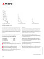
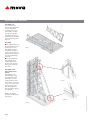
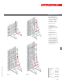
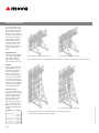
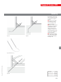
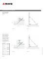
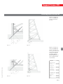
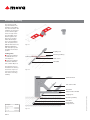
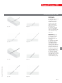
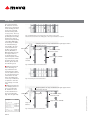
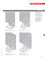
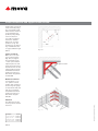
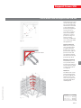
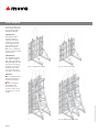
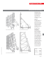
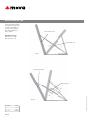
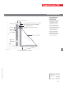
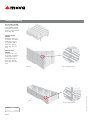
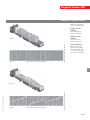
Support Frame STB Assembly and Operating Instructions Fig. 2.1 Support frame STB 450 Fig. 2.2 Support frame STB 300 Fig. 2.3 Brace bracket SK 150 Product features The support frames are mainly used for pouring against existing structures (walls, rock, soil, sheet piling, foundations etc.) if only one side of the formwork can be erected. Usually, it is not practical to tie through the forms. Therefore, the total concrete pressure has to be transferred from the formwork via a support structure into the foundation. The MEVA support frames are painted steel structures. Attention Check on site to make sure that the occurring tensile forces Z and the pressures V can be safely transferred into the foundation or floor slab. Especially the concrete strength and the kind of rebar used need to be reviewed. If the support frames are used on top of slabs make sure to support the slab where the vertical forces occur in order to transfer these into the foundation. See the Load Charts (separate book) for details about concrete pressure and anchor loads in standard applications. Safe working loads according to DIN 18216 Abbreviations, measurements, figures and tables The abbreviation STB is used for the support frames. The abbreviation ST is used for the StarTec formwork and the abbreviation M for the Mammut formwork. Anchor system Threadbar DW 15 Threadbar DW 20 Threadbar DW 26.5 DIN means Deutsche Industrie-Norm (German Industrial Standard). E DIN (E = Entwurf / draft) means that the DIN is in draft status and not yet approved of. Any further abbreviations are explained where they are used the first time. When using the support frames the following points need to be looked at with special care: Foundations and floor slabs etc. must be able to resist the transmitted loads (a static calculation might be required). The "opposite side" of the singlesided formwork, i.e. the existing structure must be able to resist the concrete pressure as well. Anchors must be able to resist the transferred loads. Anchors must not be welded, heated or deformed. In case of more complicated or special cases not dealt with in these instructions, please contact the MEVA experts for advice. Deviations from these instructions always require engineering calculations and a separate static proof. Measurements: These instructions use the metric system and thus m (for metre), cm (for centimetre) and mm (for millimetre). Dimensions without a measure are in cm. The page numbers in these instructions start with the product abbreviation STB. The figures and tables are numbered per page. Depending on its product abbreviation, a cross reference in the text refers to a page, table or figure in these instructions or in other instructions. Updated 3 December 2008 STB2 stbava-gb.pdf St. 3/12/08 Printed in Germany Safe working load 90 kN 160 kN 250 kN stbava-gb.pdf St. 3/12/08 Printed in Germany Please note Contents These Assembly and Operating Instructions contain information, instructions and hints describing how to use the MEVA equipment on the construction site in a proper, quick and economic way. Most examples shown are standard applications that will occur in practice most often. For more complicated or special applications not covered in these instructions, please contact the MEVA experts for advice. Support frame STB 300 ........................................................................ 4 Support frame STB 450 ........................................................................ 5 Preassembly of STB units ..................................................................... 6 Diagonal bracing .................................................................................. 7 Working platforms .............................................................................. 8 Anchoring ............................................................................................. 9 Anchoring details for STB 300 ........................................................... 10 Anchoring details for STB 450 ........................................................... 11 Anchoring auxiliary ............................................................................ 12 Anchoring (step by step) ................................................................... 13 Stop ends ............................................................................................ 14 Corner bracket STB and support frame STB 300 .............................. 16 Corner bracket STB and support frame STB 450 .............................. 17 Crane ganging .................................................................................... 18 Moving STB units with trolley ........................................................... 19 Brace bracket SK 150.......................................................................... 20 Transport: Stacking ............................................................................ 22 Transport: Loading of trucks ............................................................ 23 Service ................................................................................................. 24 Product List ......................................................................................... 27 Load Charts ......................................................................................... 43 When using our products the federal, state and local codes and regulations must be observed. Many of the details shown do not illustrate the wall formwork system in the ready-to-pour condition as to the aforementioned safety regulations. Please adhere to these technical instructions when applying the equipment described here. Deviations require engineering calculations and analysis to guarantee safety. Please observe the assembly instructions that your local contractor or employer has created for the site on which the MEVA equipment is used. Such instructions are intended to minimise site-specific risks and must contain the following details: The order in which all working steps including assembly and disassembly must be carried out The weight of the panels and other system parts The type and number of ties and braces as well as the distance between them The location, number and dimensions of working scaffolds including working area and protection against falling down Pick points for panel transport by crane. With regard to panel tranport, please observe these Assembly and Operating Instructions. Any deviation will require a static proof. Important: Generally, only well maintained material may be used. Damaged parts must be replaced. Apply only original MEVA spare parts for replacement. Attention: Never wax or oil assembly locks. STB3 STB Support Frame STB Support frame STB 300 For static and economical reasons we recommend using the STB in combination with panels in horizontal position. Unit Pouring height The support frame STB 300 can be used for a pouring height up to 3.30 m. Horizontal panels The STB 300 can be attached to the formwork at the tie holes with fixing screws 35 and flange nuts 100 (Fig. 4.4 and 4.5) or it can be screwed to the multifunction profiles of the panels with flange screws 18. Fig. 4.2 StarTec formwork Unit Fig. 4.3 Mammut formwork Fig. 4.1 Support frame STB 300 with panels in horizontal position Attention Before mounting the STB to the formwork panel, set spindle at middle position. Description Fig. 4.5 Detail – Fixing screw at the side of the facing Unit Fig. 4.7 StarTec formwork Ref. No. Support frame STB 300 ...................... 29-402-62 Fixing screw 35/DW15 .................... 29-401-20 Articulated flange nut 15/120........................ 29-900-10 Cross beam 300.......... 29-403-05 Flange screw 18 .......... 29-401-10 Flange screw 28 .......... 29-401-12 STB4 Fig. 4.4 Detail – Fixing screw at the side of the STB Unit Fig. 4.6 Support frame STB 300 with panels in vertical position Fig. 4.8 Mammut formwork stbava-gb.pdf St. 3/12/08 Printed in Germany Vertical panels The STB 300 can be used together with the cross beam 300 (Fig. 4.6). Placed horizontally between the formwork panel and support frame, the cross beam 300 allows the building of units while the distance between the support frames is arbitrary. The cross beam 300 is designed to match the StarTec (Fig. 4.7) and Mammut (Fig. 4.8) formwork systems. Support Frame STB Fig. 5.1 Up to a formwork height of 5.00 m: 3 flange screws per STB are recommended Fig. 5.2 Up to a formwork height of 6.50 m: 4 flange screws per STB are recommended Possible Use The STB 450 is designed for singlesided formwork up to 5.00 m (Fig. 5.1). By using height extensions 150 and other equipment, formwork can be erected at the following heights: 6.50 m – 1 height extension (Fig. 5.2) 8.00 m – 2 height extensions, base extensions, Triplex SB braces 9.50 m – 3 height extensions, base extensions, Triplex SB braces (Fig. 5.3) 11.00 m – 4 height extensions, base extensions, Triplex SB braces (Fig. 5.4) 12.50 m – 4 height extensions, base extensions, Triplex SB braces Depending on the site and feasible Triplex bracing, support frame constructions for formwork of 14.00 m or higher can be built. stbava-gb.pdf St. 3/12/08 Printed in Germany Attachment The STB 450 can be attached to the formwork at the tie holes with fixing screws 35 and flange nuts 100 or it can be screwed to the multifunction profiles of the panels with flange screws 18. Description Fig. 5.3 Up to a formwork height of 9.50 m: 6 flange screws per STB are recommended Fig. 5.4 Up to a formwork height of 11.00 m: 7 flange screws per STB are recommended Ref. No. Support frame 450 ..... 29-406-00 Height extension 150 .. 29-406-10 Base extension ............ 29-406-20 Fixing screw 35/DW15 .................... 29-401-20 Articulated flange nut 15/120........................ 29-900-10 Flange screw 18 .......... 29-401-10 STB5 STB Support frame STB 450 Preassembly of STB units Assembly area The area where the formwork and STB units ares preassembled should be clean, even and capable of taking the expected weight. The support frames are attached at the backside of the formwork panels (Fig. 6.1). Fig. ig. 6.1 Assembly of the heavy duty braces Triplex Depending on the overall height, it may be required to attach Triplex braces to the height and base extensions. All the accessories for the connection (nuts, bolts and pins) come with the height and base extenstions (Fig. 6.2 through 6.4). Fig. 6.3 Observe the Triplex assembly and operating instructions. Fig. 6.4 Fig. 6.2 STB6 stbava-gb.pdf St. 3/12/08 Printed in Germany Assembly The support frame can be attached to the formwork at the tie holes with fixing screws 35 and flange nuts 100 or it can be screwed to the multifunction profiles of the panels with flange screws 18. The preassembled units should rest on square timbers (face down) on the ground before they are flown into place. Support Frame STB Diagonal bracing Scaffold tubes with Ø 48.3 x 4.05 mm, bolton couplers 48/M14 and swivel-joint couplers 48/48 are necessary to build the required diagonal bracing. Units built out of STB 300 frames only need 1 horizontal tube (Fig. 7.1) Units built out of STB 450 frames need 2 horizontal and 1 diagonal scaffold tube (Fig. 7.2). Fig 7.2 72 Fig. stbava-gb.pdf St. 3/12/08 Printed in Germany STB Fig. 7.1 If height extensions are used, one additional horizontal scaffold tube per height extension is required from the second height extension on (Fig. 7.3 and 7.4). Description Ref. No. Scaffold tube 48/200........................ 29-412-23 48/300........................ 29-412-26 48/400........................ 29-412-27 Fig. 7 Fig 7.3 3 Fig. Fig 7.4 74 Swivel-joint coupler 48/48.......................... 29-412-52 Bolt-on coupler 48/M14 ...................... 40-080-70 STB7 Working platforms IThe scaffolding brackets 90 and 125 together with guardrailing posts can be used to build a working platform. The procedure is as with a twosided wall formwork. For details see the Assembly and Operating Instructions of the formwork you are using. For a safe access to the platform we recommend using the MEVA Stair Tower. Admissible load 150 kg/m², scaffold group 2 according to DIN 4420, part 1. Max. influence width 2.00 m, planking with classification SH 10. Fig. 8.1 STB 300 and Mammut formwork Fig. 8.2 STB 300 and StarTec formwork Attachment of boards at scaffolding bracket with bolts ∅ 10 mm and a minimum length of 110 mm Platform layout Since the STB units can be built in a flexible way and combined with different formwork systems with different heights, check and determine in the planning stage what platform layout will be used. Make sure to observe the maximum permissible fall height. Description Ref. No. Scaffolding bracket 90.............................. 29-106-00 125............................. 29-106-50 Guard-railing post 100 29-106-75 Guard-railing post 140 29-106-85 Side railing 90/100 ...... 29-108-20 Side railing 125/100 .... 29-108-30 STB8 Fig. 8.3 STB 450 and Mammut formwork Fig. 8.4 STB 450 and StarTec formwork Attachment of boards at scaffolding bracket or extensions with bolts ∅ 10 mm and a minimum length of 110 mm stbava-gb.pdf St. 3/12/08 Printed in Germany STB 450 When using the STB 450 support frame we recommend bolting planks or boards to the support frame or height extension (Fig 8.3 and 8.4). The holes for the attachment of height extensions can be used. The STB 450 and height extensions 150 provide pockets for sliding in the guard-railing posts. Support Frame STB Anchoring Fig. 9.2 STB Fig. 9.1 Depending on the load, there are different ways to anchor the support frames: Anchor loop 15 (20) in combination with the cross stiffener 44 (Fig. 9.1 and 9.2). Anchor loop in turned configuration if support frame sits on top of a slab, see fig. 9.2 for an example. It needs to be discussed with the stress analyst if an additional rebar is required. Anchoring by using a 20 or 26.5 mm threadbar and twin channel 80 or 245 (Fig. 9.4). stbava-gb.pdf St. 3/12/08 Printed in Germany Fig. 9.3 Anchor loop Description Fig. 9.4 Ref. No. Cross stiffener 44 ....... 29-401-02 Twin channel 245/22... 29-406-30 Twin channel 80/22..... 29-406-35 Twin channel 80/12..... 29-406-38 STB9 Anchoring details for STB 300 25 25 Figures 10.1 and 10.2 show an STB 300 with panels in horizontal position. 17 17 Fig. 10.1 Fig. 10.2 Figures 10.3 and 10.4 show an STB 300 with panels in vertical position, e.g. for corner solutions. When using the STB we recommend anchor loop 15. If the corner bracket is used, we recommend using single threadbars in the corner area. Ref. No. 25 Coupling nut 15 (SW 30) ................. 29-900-55 20 (SW 36) ................. 29-900-50 Tie rod DW 15/90 ....... 29-900-80 Tie rod DW 20/120 ..... 29-900-97 Flange nut 100 ........... 29-900-20 Articulated flange nut 15/120........................ 29-900-10 20/140........................ 29-900-05 Anchoring auxiliary 15 STB ........................ 29-001-50 M alignment rail 44 .... 29-401-02 STB10 27 Fig. 10.3 27 Fig. 10.4 stbava-gb.pdf St. 3/12/08 Printed in Germany Anchor loop 15........... 29-001-20 Anchor loop 20........... 29-001-25 25 Description Support Frame STB Anchoring details for STB 450 17 ≥ 50 ≥ 50 Figures 11.1 and 11.2 show an STB 450 with panels in horizontal position. 17 Figures 11.3 and 11.4 show an STB 450 with panels in vertical position, e.g. for corner solutions. For the amount and type of required threadbars (DW 15, DW 20 or DW 26.5) see the Load Charts (separate manual). Description Ref. No. Hexagonal nut 20 (SW 36) ................. 29-900-61 26.5 (SW 46) .............. 29-900-58 27 Tie rod DW 26.5/80 .... 29-900-75 Coupling nut 26.5 ..... 29-900-56 Fig. 11.4 Twin channel 245/22........................ 29-406-30 80/22.......................... 29-406-35 80/12.......................... 29-406-38 Fig. 11.3 27 50 ≥ 50 Counter plate 120x120x20/25 .......... 29-900-35 120x120x20/38 .......... 29-900-30 ≥ stbava-gb.pdf St. 3/12/08 Printed in Germany Anchoring auxiliary 20 STB ........................ 29-001-55 26.5 STB ..................... 29-001-60 STB11 STB Fig. 11.2 Fig. 11.1 Anchoring auxiliary The anchoring auxiliary STB facilitates the installing of threadbars into the foundation. The auxiliaries are attached to the rebar and guarantee an angle of 45°. The threadbar can be slid through the auxiliary at any position, which allows adapting to any foundation size. The plastic sleeve (DW 15 without thread, DW 20 and DW 26.5 with thread) keeps the threadbar at the ideal position. Fig. 12.1 Coupling nut Packing units Anchoring auxiliary 15 STB: One unit contains 50 pieces. Anchoring auxiliary 20 and 26.5 STB: One unit contains 40 pieces. The plastic sleeves are included in the delivery and on site only need to be pressed into the hole of the anchoring auxiliary. Anchoring auxiliary Plastic sleeve Threadbar Fig. 12.2 Wall formwork Twin channel 245 Threadbar Support frame STB 450 Anchoring auxiliary Description Ref. No. Anchoring auxiliary 15 STB ........................ 29-001-50 20 STB ........................ 29-001-55 26.5 STB ..................... 29-001-60 STB12 Threadbar Counterplate Hexagonal nut Fig. 12.3 stbava-gb.pdf St. 3/12/08 Printed in Germany Coupling nut Support Frame STB Anchoring (step by step) stbava-gb.pdf St. 3/12/08 Printed in Germany Fig. 13.2 Fig. 13.3 Fig. 13.4 Fig. 13.5 Fig. 13.6 Fig. 13.7 Fig. 13.8 Threadbars DW 20 and DW 26.5 1. Attach the counter plate 120 and the hexagonal nut to the threadbar. 2. Install the threadbars by using the anchoring auxiliary 20 STB or 26.5 STB which can be attached to the rebar. The threadbar must be completely screwed into the hexagonal nut (Fig. 13.5 and 13.6). Observe the required concrete cover! 3. Screw the coupling nut onto the (extension) threadbar (Fig. 13.7) and then both on the (cast in) threadbar (Fig. 13.8). STB13 STB Fig. 13.1 Anchor loop DW 15/DW 20 1. Install the anchor loop by using the anchoring auxiliary 15 STB or 20 STB which can be attached to the rebar (Fig. 13.1 and 13.2). Observe the required concrete cover! 2. Screw the coupling nut on the threadbar (Fig. 13.3) and then both onto the anchor loop (Fig. 13.4). top The stop end bracket SB 110 can be used for walls up to 110 cm thick. It has a sliding part that at the stop end is slid until the existing wall etc. (Fig. 14.2 ). The stop end bracket is mounted by sliding it horizontally between the support frames and by attaching a threadbar DW 15/45 and a flange nut 100 or an articulated flange nut 15/120 to the nuts of the multi-function profiles of the panels (StarTec, Mammut or Mammut 350). This way the support frame is located between the formwork panel and the stop end bracket. When mounting the stop end bracket, please observe the following cases: bottom Stop ends Fig. 14.1 Mammut panel for horizontal use; the bottom of the panel must be directed to where the sliding part of the stop end bracket is required Clamping device for stop end bracket through support frame M panel 250 (horizontal) Sliding part Flange nut Threadbar in multifunction profile Support frame STB 450 Stop end bracket Fig. 14.2 Mammut panel for horizontal use Mammut formwork: Description Clamping device for stop end bracket through support frame ST panel 270 (horizontal) Sliding part Flange nut Ref. No. Stop end bracket SB 110 ........................ 29-406-40 Clamping device for stop end bracket SB 110 ........... 29-406-60 Flange nut 100 ........... 29-900-20 Articulated flange nut 15/120........................ 29-900-10 Tie rod DW 15/45 ....... 29-900-76 STB14 Fig. 14.3 StarTec panel for horizontal use Threadbar in multifunction profile Support frame STB 450 Stop end bracket Fig. 14.4 StarTec panel for horizontal use stbava-gb.pdf St. 3/12/08 Printed in Germany When attaching the stop end bracket at a horizontal panel, make sure the panel is turned in a way that its bottom is directed to the side where the sliding part of the stop end bracked is required to form the stop end (Fig. 14.1 und 14.2). Mammut and StarTec: The clamping device for the stop end bracket SB 110 must be used for the attachment of the stop end bracket (Fig. 14.1 through 14.4). Support Frame STB Stop ends Figures 15.1 through 15.4 show formwork and support frames with different heights and the required number of stop end brackets. Please note that an STB 450 with 3 height extensions 150 requires 6 stop end brackets while an STB 450 with 4 height extensions requires 7 stop end brackts. Fig. 15.2 An STB 300 requires 2 stop end brackets An STB 450 requires 3 stop end brackets Fig. 15.3 Fig. 15.4 An STB 450 with 1 height extension 150 requires 4 stop end brackets An STB 450 with 2 height extensions 150 requires 5 stop end brackets stbava-gb.pdf St. 3/12/08 Printed in Germany STB Fig. 15.1 STB15 23 17 23 41.5 85.5 Fig. 16.1 StarTec formwork Make sure to use panels in vertical position (Fig. 16.3). To support the joint between the "corner" panel and the adjacent panel use horizontal steel rails and set back the anchors for the support frame by 10 cm. A maximum formwork height of 3.30 m is possible when using StarTec and STB 300. 23 17 23 M alignment rail 44 Fig. 16.2 Ma x. Attention The dimensions for the anchor positions must be observed. Fig. 16.3 Description Ref. No. Corner bracket STB ..... 29-406-70 Flange screw 18 .......... 29-401-10 M alignment rail 44 .... 29-401-02 Twin channel 80/12..... 29-406-38 STB16 25 0c m stbava-gb.pdf St. 3/12/08 Printed in Germany Mammut formwork You should use a "corner" panel in vertical position and continue to use the large size gangs as usual. Horizontal steel rails are not required. A maximum formwork height of 3.30 m is possible when using the STB 300. 85.5 84 Singlesided corner areas can be formed by using the corner bracket STB which must be attached to the multifunction profiles by using flange screws 18. Each corner requires 2 support frames. For detailed dimensions of anchor positions see fig. 16.1 and 16.2. For the anchoring of STB brackets also see pages STB-9 through STB-13. 41.5 Corner bracket STB and support frame STB 300 Support Frame STB Corner bracket STB and support frame STB 450 43.5 87.5 Fig. 17.1 63 Twin channel 80/22 Mammut formwork You should use a "corner" panel in vertical position and continue to use the large size gangs as usual. Steel rails are not required. Fig. 17.2 Ma x. stbava-gb.pdf St. 3/12/08 Printed in Germany StarTec formwork Make sure to use panels in vertical position. To support the joint between the "corner" panel and the adjacent panel use horizontal steel rails and set back the anchors for the support frame by 10 cm. 25 0c m Attention The dimensions for the anchor positions must be observed. Make sure that the inside corner and "corner" panel are absolutely flush when installing them. Description Fig. 17.3 Ref. No. Corner bracket STB ..... 29-406-70 Flange screw 18 .......... 29-401-10 Twin channel 80/22..... 29-406-35 STB17 STB 63 87.5 87 43.5 Singlesided corner areas can be formed by using the corner bracket STB which must be attached to the multifunction profiles by using flange screws 18. Each corner requires 2 support frames. For detailed dimensions of anchor positions see fig. 17.1 and 17.2. For the anchoring of STB brackets see also pages STB-9 through STB-13. Crane ganging For crane ganging, each panel must be attached to the support frame STB 300 or STB 450. STB 300 units STB 300 units with a maximum width of 3.50 m are moved by using the crane hook of the wall formwork system which is used (Fig. 18.1 and 18.2). Make sure to always use 2 crane hooks and watch their capacity. STB 450 units The STB 450 and extension 150 are equipped with crane eyes. When flying STB 450 units with extensions, crane slings should be used and be attached at the crane eyes of the top extension (Fig. 18.3 and 18.4). Fig. 18.1 Mammut and STB 300 Fig. 18.2 StarTec and STB 300 Fig. 18.3 Mammut and STB 450 Fig. 18.4 Mammut 350 and STB 450 STB18 stbava-gb.pdf St. 3/12/08 Printed in Germany Attention Do not strip STB units by breaking them free from the concrete by crane! When setting STB units down to the ground make sure they do not tilt over. If necessary use a counter weight. Support Frame STB Moving STB units with trolley STB units can easily and quickly be moved around on the job with the trolley waler if a crane cannot be used, e.g. in tunnels. The trolley waler can be mounted to the STB 300 and STB 450. stbava-gb.pdf St. 3/12/08 Printed in Germany Fig. 19.1 STB 300 with trolley waler Fig. 19.2 STB 300 with trolley waler Assembly of the trolley waler The trolley waler is bolted to the support frames (counter plates and nuts are already attached to the waler). When moving the unit, a counter weight is necessary to avoid tilting over (the weight depends on the formwork height and support frame). One unit requires 2 trolley walers, 4 wheel adapters and 4 trolley spindles 48/70. Depending on the weight, 4 swivel type castors of 2 or 6 or 10 tons are required. The wheels are mounted to the waler by raising the unit with the spindle. Description Ref. No. Trolley waler Trolly waler ................. 29-403-70 Wheel adapter ............ 29-403-75 Spindle 48/70 ............. 29-403-80 Fig. 19.3 STB 450 with trolley waler Fig. 19.4 STB 450 with trolley waler Swivel type castor 2 t .............................. 29-306-50 6 t .............................. 29-306-75 10 t ............................ 29-306-90 STB19 STB Attention The support frames must not stand on trolley spindles while pouring. When using the STB 300 make sure to remove the trolley waler adjacent to the panels; otherwise anchoring is not possible. Observe the trolley waler instructions. Brace bracket SK 150 The brace bracket SK 150 is used to form stop ends of slabs or foundations, even on sloped surfaces (Fig. 20.1 and 20.2). See also p. STB-21. Brace bracket SK 150 Adjustment range SRL 120 = 51° 106° SRL 170 = 80° 110° Brace SRL 120 Fig. 20.1 Brace bracket SK 150 Fig. 20.2 Description Ref. No. Brace bracket SK 150 .. 29-403-50 Brace SRL 120 ............. 29-108-80 Brace SRL 170 ............. 29-108-90 STB20 stbava-gb.pdf St. 3/12/08 Printed in Germany Brace SRL 170 Support Frame STB Brace bracket SK 150 Support for power screed Brace bracket SK 150, max. distance = 140 cm (max. fresh concrete pressure 20 kN/m²) Joint seal Positioning support SK Insulation Wood spacer, depending on width of joint 150 Concr. pressure max. 20 kN/m² Mammut 250/75 alkus facing Brace SRL 120 (170) Typical application: Foundation slab with joint tape The positioning support SK allows for an exact levelling and positioning of the stop end, even on sloped surfaces. The brace bracket can easily be attached to the Dywidag threaded nuts of formwork panels. The braces SRL 120 or 170 and the positioning support SK must be ordered separately. Inner joint tape (waterstop) STB Base seal Fig. 21.1 stbava-gb.pdf St. 3/12/08 Printed in Germany 4 Fischer anchors FHA 18 or similar Description Ref. No. Positioning support SK............................... 29-403-55 Flange screw 18 .......... 29-401-10 Flange screw 28 .......... 29-401-12 STB21 Transport: Stacking Brace bracket SK 150 To transport brace brackets, use MEVA stacking racks. One rack takes 25 brackets, folded without braces (Fig. 22.1). Suppport frame STB 300 10 support frames can be stacked. To facilitate stacking, the frames are equipped with a welded-on stacking device (Fig. 22.2 and 22.3). Fig. 22 Fig 22.1 1 Support frame STB 450 4 support frames can be stacked. To facilitate stacking, the frames are equipped with a welded-on stacking device (Fig. 22.4 und 22.5). Fig. 22.3 Stacking device Fig. 22.4 Fig. 22.5 Stacking device Description Ref. No. Stacking rack .............. 27-000-20 STB22 stbava-gb.pdf St. 3/12/08 Printed in Germany Fig. 22.2 Support Frame STB Transport: Loading of trucks Make sure that all material is secured properly. Suppport frame STB 300 6 x 10 = 60 frames (Fig. 23.1 and 23.2) Suppport frame STB 450 3 x 4 = 12 frames (Fig. 23.3 and 23.4) Max. transport length: 13.60 m (Europe) Safety regulations When using or transporting our products, the federal, state, and local codes and regulations must be observed. STB Fig. 23.2 Max. transport width: 2.50 m (Europe) Fig. 23.1 Fig. 23.4 Max. transport length: 13.60 m (Europe) Max. transport width: 2.50 m (Europe) stbava-gb.pdf St. 3/12/08 Printed in Germany Fig. 23.3 STB23 Service Cleaning and regeneration of wall formwork Cleaning is done using industrial equipment with assembly lines. The regeneration is carried out as follows: The frames are checked and, if necessary, repaired, painted and provided with a new facing. As long as the formwork equipment is up-todate, a regeneration will always be a more economical solution than purchasing new formwork. Please note that the cleaning and regeneration service is not available in all countries in which MEVA does business. Rentals With much equipment on stock, we offer our customers the option of renting supplementary material during peak times. We also give prospective customers the chance to test MEVA formwork so they can see its benefits for themselves in actual use. STB24 RentalPlus Since MEVA started the flat rate for cleaning and repair of rented formwork systems in early 2000, more and more contractors experience the outstanding advantages. Ask our representatives about the details! Formwork drawings Of course, all offices in our technical department have CAD facilities. You get expert, clearly represented plans and work cycle drawings. MBS MEVA Basic Support MBS is an addition to AutoCAD, developed by MEVA Formwork Systems in 2000. MBS is based on standard programs (AutoCAD and Excel) and can be used on any PC that has these two programs installed. It includes pull down menues for AutoCAD and applications to ease forming. It also includes the possibility to create takeoffs. Special solutions We can help with special parts, custom-designed for your project, as a supplement to our formwork systems. Static calculations Generally, this is only necessary for applications like singlesided formwork where the anchor parts are embedded in the foundation or the base slab. If requested, we can perform static calculations for such applications at an additional charge. Formwork seminars To make sure that all our products are used properly and efficiently, we offer formwork seminars. They provide our customers a good opportunity to keep themselves up-to-date and to benefit from the know-how of our engineers. stbava-gb.pdf St. 3/12/08 Printed in Germany Support frame cleaning The parts of the support frame STB are cleaned professionally upon return. STB Notes STB25 Notes STB26