1
Technical Data and Dimension Drawings
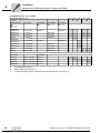
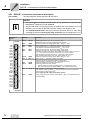
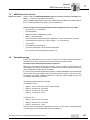
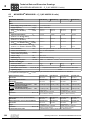
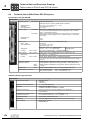
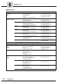
MOVIDRIVE® MDX60/61B electronics data
8.5
kVA
i
f
n
8
P Hz
MOVIDRIVE® MDX60/61B electronics data
MOVIDRIVE® MDX60/61B
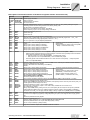
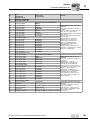
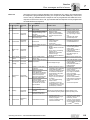
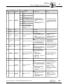
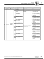
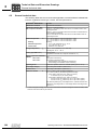
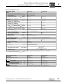
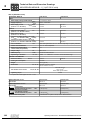
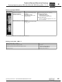
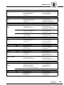
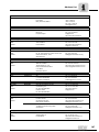
General electronics data
Power supply
for setpoint input
Setpoint input n1
X11:1
X11:5
X11:2/X11:3
(differential input)
Operating mode AI11/AI12
Resolution
Internal resistance
REF1: DC+10 V +5 % / –0 %, Imax = DC 3 mA
REF2: DC–10 V +0 % / –5 %, Imax = DC 3 mA
Reference voltages for setpoint potentiometer
AI11/AI12: Voltage or current input, can be set with S11 and P11_, sampling interval 1 ms
Voltage input:
n1 = DC 0...+10 V or DC –10 V...0...+10 V
12 bit
Ri = 40 kΩ (external voltage supply)
Ri = 20 kΩ (supply from REF1/REF2)
Current input:
n1 = DC 0...20 mA or DC 4...20 mA
11 bit
Ri = 250 Ω
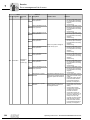
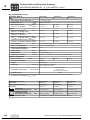
Internal setpoints
Parameter set 1: n11/n12/n13 = –6000...0...+6000 min-1
Parameter set 2: n21/n22/n23 = –6000...0...+6000 min-1
Time ranges of the speed ramps
at Δn = 3000 min-1
1. Ramp
2. Ramp
Stop ramp
Emergency ramp
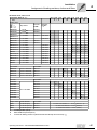
Motor potentiometer
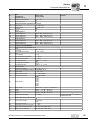
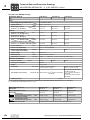
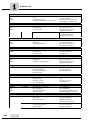
Auxiliary voltage output1)
X13:8/X10:8
VO24: VOUT = DC 24 V, maximum current carrying capacity Imax = DC 400 mA
External voltage supply1) X10:9
VI24: UIN = DC 24 V –15 % / +20 % according to EN 61131-2
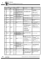
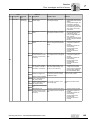
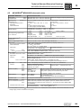
Binary inputs
X13:1...X13:6 and X16:1/X16:2
Internal resistance
Isolated (optocoupler), PLC compatible (EN 61131), sampling interval 1 ms
DIØØ...DIØ5 and DIØ6/DIØ7
Ri ≈ 3 kΩ, IE ≈ DC 10 mA
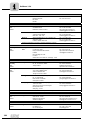
t11/t21
t12/t22
t13/t23
t14/t24
t3
Up: 0...2000 s
Down: 0..2000 s
Up = down: 0...2000 s
Down: 0..0.20 s
Down: 0..0.20 s
Up: 0.2..0.50 s
Down: 0.2..0.50 s
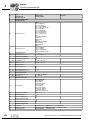
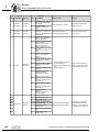
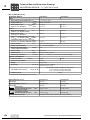
Signal level
DC +13 V...+30 V= "1" = Contact closed
DC–3 V...+5 V = "0" = Contact open
Function
X13:1
X13:2...X13:6, X16:1/X16:2
DIØØ: fixed assignment with "/Controller inhibit"
DIØ1...DIØ5, DIØ6/DIØ7: Selection option → Parameter menu P60_
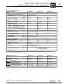
Binary outputs1)
X10:3/X10:7 and X16:3...X16:5
Signal level
PLC-compatible (EN 61131-2), response time 1ms
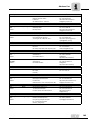
DBØØ/DOØ2 and DOØ3...DOØ5
"0" = DC 0 V
Function
X10:3
X10:7, X16:3...X16:5
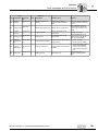
Relay output
Function
X10:4...X10:6
"1" = DC +24 V
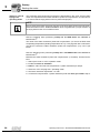
Caution: Do not apply external voltage!
DBØØ: With fixed assignment "/Brake", Imax = DC 150 mA, short-circuit proof, protected against
external voltage to DC 30 V
DOØ2, DOØ3...DOØ5: Selection option → Parameter menu P62_,
Imax = DC 50 mA, short-circuit proof, protected against external voltage to DC 30 V
DOØ1: Load capacity of the relay contacts Umax = DC 30 V, Imax = DC 800 mA
X10:4
X10:5
X10:6
DOØ1-C: Shared relay contact
DOØ1-NO: Normally open contact
DOØ1-NC: NC contact
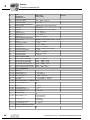
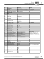
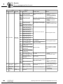
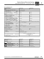
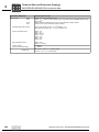
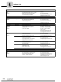
System bus (SBus)
X12:1
X12:2
X12:3
DGND: Reference
potential
SC11: SBus high
SC12: SBus low
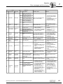
RS485 interface
X13:10
X13:11
ST11: RS485+
ST12: RS485-
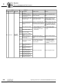
TF/TH/KTY input
X10:1
TF1: Response threshold at RTF ≥ 2.9 kΩ ±10 %
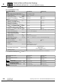
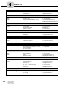
Reference terminals
X11:4
X12:1/X13:9/X16:6/X10:2/X10:10
X13:7
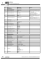
Permitted cable cross section
According to EN 61131
Selection option → Parameter menu P62_
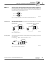
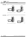
CAN bus according to CAN specification 2.0, parts A and B, transmission technology according to ISO 11898, max. 64 stations, terminating resistor (120Ω) can be activated using DIP switch.
EIA standard, 9.6 kBaud, max. 32 stations
Max. cable length 200 m
Dynamic terminating resistor with fixed installation
AGND: Reference potential for analog signals and terminals X11:1 and X11:5 (REF1/REF2)
DGND: Reference potential for binary signals, system bus, RS485 interface and TF/TH
DCOM: Reference potential for binary inputs X13:1...X13:6 and X16:1/X16:2 (DIØØ...DIØ5
and DIØ6/DIØ7)
One core per terminal:
Two cores per terminal:
0.20..0.2.5 mm2 (AWG 24..0.12)
0.25...1 mm2 (AWG 22...17)
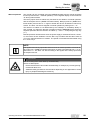
1) The unit provides a current of Imax = DC 400 mA for the DC+24 V outputs (VO24, binary outputs). If this value is insufficient, a DC 24 V
voltage supply must be connected to X10:9 (VI24).
Operating Instructions – MOVIDRIVE® MDX60B/61B Inverter
143