1
,167$//$7,21
0$18$/
0$'(
,1
,7$/<
!"#$ $"% !"&"'($)""*"+%,-$"%% !".+%"%&")+'+"/0
1!"
&"'($)""*"+%
!"
#
!"" #
,
$#
!"#$%"
&
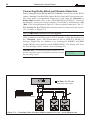
IMPORTANT: The following information is for disassembled Control Panels ONLY.
Ensure the Manual you are using corresponds to, or is a later release than the one shown
on the “RELEASE ISSUES” label inside the package (see below).
DO NOT attempt to assemble or install the Control Panel until you have the respective
Release.
The Manual Release Number can be found at the bottom of the last page, between the
Code and Date (see below).
0DQXDO
5HOHDVH
1XPEHU
&RGH
'DWH
BENTEL SECURITY srl reserves the right to modify the technical specifications of this product without prior notice.
3
TABLE OF CONTENTS
Section 1 - Identification of Parts ....................................... 6
The ALISON-S and ALISON-DVP LCD Keypads ...................................... 6
The ALISON/32LP and ALISON/8L LED Keypads ................................... 7
The MIA/S and MIA/D LCD Keypads ......................................................... 8
The OMNIA/TAST-R LCD Keypad .............................................................. 9
The NC2/TAST LED Keypad ................................................................... 10
The ICON/KP LED Keypad ..................................................................... 11
ECLIPSE Reader, PROXI Reader, SAT Key, PROXI-CARD ................... 13
M-IN/6 Input and M-OUT/6 Output Expanders ........................................... 15
VRX32-433 and Vector/RX8 Receiver ...................................................... 16
Section 2 - Installation ....................................................... 17
Mounting the Peripherals ........................................................................... 17
The Main Unit ............................................................................................ 17
Mounting Keypads .................................................................................... 17
Mounting PROXI Proximity Readers ......................................................... 17
Mounting ECLIPSE Readers .................................................................... 18
Input and Output Expanders ..................................................................... 18
Addressing Devices .................................................................................... 19
ALISON/8L Keypad ................................................................................... 20
ALISON/32L Keypad ................................................................................. 20
ALISON/S and ALISON/DVP Keypads ...................................................... 21
Setting up the BPI Level ............................................................................. 22
Installing the VRX32-433 and Vector/RX8 Receiver ................................. 23
Changing the batteries of Wireless Devices ............................................ 23
Connecting Peripherals .............................................................................. 24
Connecting Keypads, Readers and Expanders ........................................ 24
Alarm Detectors ....................................................................................... 26
Connecting Fire Detectors (with Repeat Outputs) ................................... 28
Alarm Siren ............................................................................................... 29
Connecting Roller-Blind and Vibration Detectors ..................................... 30
Connecting the Tamper Line ..................................................................... 31
Auxiliary Device (Open Collector) ............................................................. 32
Connecting the Telephone Line ................................................................. 33
VRX32-433 and Vector/RX8 Receiver ...................................................... 33
‘Double’ line type (only for KYO16D) ......................................................... 34
Section 3 - Programming from PC ................................... 35
Introduction ..................................................................................................
Main Window ................................................................................................
Managing the Pages .................................................................................
Managing Customers ...............................................................................
35
35
35
36
4
Multifunction Control Panel
Data Section .............................................................................................
Toolbar and toolbuttons .............................................................................
Upload, Download and Help toolbuttons ...................................................
The Menu Bar ...........................................................................................
Keypads Page ..............................................................................................
Keypads Table ..........................................................................................
Enable Keypad .........................................................................................
Keypad Type .............................................................................................
Readers Page ...............................................................................................
Readers Table ..........................................................................................
Receiver Page .............................................................................................
Expander In/Out Page .................................................................................
Zones Page ...................................................................................................
Zones Table ..............................................................................................
Type ..........................................................................................................
Balancing .................................................................................................
Attributes ..................................................................................................
Cycles ......................................................................................................
Double Pulse ............................................................................................
Partitions ..................................................................................................
Outputs Page ...............................................................................................
Outputs Table ...........................................................................................
Attributes ..................................................................................................
Monostable Times ....................................................................................
Signals .....................................................................................................
Partitions ..................................................................................................
Partitions Page ............................................................................................
Partitions Table .........................................................................................
Times .......................................................................................................
Inactivity ....................................................................................................
Negligence ................................................................................................
Phone Page ..................................................................................................
Telephone Numbers .................................................................................
Dialling ......................................................................................................
Type ..........................................................................................................
Partitions ..................................................................................................
Teleservice Page .........................................................................................
Call Attempts ............................................................................................
Accessing the DTMF Menu .......................................................................
Export to WinBcs .....................................................................................
Test Event .................................................................................................
Logger Page .................................................................................................
Events page .................................................................................................
Priority Event ............................................................................................
37
37
37
38
44
44
44
44
45
45
46
47
48
48
49
49
50
52
53
53
54
54
54
55
55
58
59
59
60
61
61
62
62
62
63
63
64
64
64
64
65
66
67
70
5
Scheduler Page ...........................................................................................
Scheduler Table ........................................................................................
Options Page ...............................................................................................
Options .....................................................................................................
Auto-Reset Memory ..................................................................................
Code Page ....................................................................................................
User Code Table .......................................................................................
Quick Arm .................................................................................................
Wireless Key Codes ................................................................................
Installer Code ...........................................................................................
Programming User Code PINs .................................................................
Key/Card Page .............................................................................................
Keys/Cards Table .....................................................................................
Wireless Keys Page .....................................................................................
Clock Page ...................................................................................................
Programming from Computer (via serial Link) ..........................................
Programming via Modem ............................................................................
73
73
74
74
78
79
79
80
80
81
81
82
82
83
84
84
86
6
Multifunction Control Panel
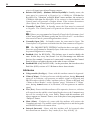
SECTION 1 - IDENTIFICATION OF PARTS
The numbers in boldface (in square brackets) refer to the hardware parts described in this Manual, and other Manuals relevant to this product.
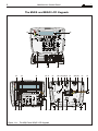
The ALISON-S and ALISON-DVP LCD Keypads
$/,621'93
$/,6216
'HV
3,1
9^cUbY]U^d_123_4
1b]Y^WDi`U123_b4
4
3,1
47
4YcY^cUbY]U^d_1bUU
4YcQb]Y^W@QbdYdY_^c
3,1
BUcUd=U]_bYU
BUcUd1\Qb]c
3,1
2\_SS_1\\Qb]U
Cd_`1\Qb]c
3,1
3,1
1bUU
9^cUbYdU
1b]UT
@QbdYdY_^c
1\\Qb]U
1\Qb]
7eQcd_
=UccQWU
!
"#
Q
$
9^cUbY]U^d_1bUU
1b]Y^W@QbdYdY_^c
3,1
3,1
BUcUd=U]_bYU
BUcUd1\Qb]c
3,1
2\_SS_1\\Qb]U
Cd_`1\Qb]c
3Q^SU\\QDU\UV_^QdU
3\UQb3Q\\c
3,1
E
9^cUbY]U^d_123_4
1b]Y^WDi`U123_b4
4
3,1
47
4YcY^cUbY]U^d_1bUU
4YcQb]Y^W@QbdYdY_^c
3,1
D
'HV
GQb^Y^W
=UccQWWY_
3Q^SU\\QDU\UV_^QdU
3\UQb3Q\\c
$
9^cUbY]U^d_1bUU
1b]Y^W@QbdYdY_^c
Q
1bUU
9^cUbYdU
1b]UT
@QbdYdY_^c
1\\Qb]U
1\Qb]
7eQcd_
=UccQWWY_
GQb^Y^W
=UccQWU
!
"#
F
$
D Figure 1.1a - The ALISON-S and ALISON-DVP LCD Keypads
D E
F
E 7
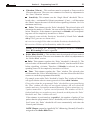
Section 1 - Identification of Parts
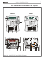
The ALISON/32LP and ALISON/8L LED Keypads
'HV
Q
9^cUbY]U^d_1bUU
1b]Y^W@QbdYdY_^c
3,1
3,1
BUcUd=U]_bYU
BUcUd1\Qb]c
3,1
2\_SS_1\\Qb]U
Cd_`1\Qb]c
3,1
3,1
$
1bUU
9^cUbYdU
1b]UT
@QbdYdY_^c
1\\Qb]U
1\Qb]
7eQcd_
=UccQWU
!
"#
Q
$
9^cUbY]U^d_1bUU
1b]Y^W@QbdYdY_^c
3,1
9^cUbY]U^d_123_4
1b]Y^WDi`U123_b4
4
3,1
47
4YcY^cUbY]U^d_1bUU
4YcQb]Y^W@QbdYdY_^c
3,1
BUcUd=U]_bYU
BUcUd1\Qb]c
3,1
2\_SS_1\\Qb]U
Cd_`1\Qb]c
3,1
3Q^SU\\QDU\UV_^QdU
3\UQb3Q\\c
3,1
1bUU
9^cUbYdU
1b]UT
@QbdYdY_^c
1\\Qb]U
1\Qb]
7eQcd_
GQb^Y^W
=UccQWWY_
=UccQWU
!
"#
'HV
GQb^Y^W
=UccQWWY_
3Q^SU\\QDU\UV_^QdU
3\UQb3Q\\c
9^cUbY]U^d_123_4
1b]Y^WDi`U123_b4
4
3,1
47
4YcY^cUbY]U^d_1bUU
4YcQb]Y^W@QbdYdY_^c
$
Figure 1.1b - The ALISON/32LP and ALISON/8L LED Keypads
8
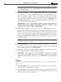
Multifunction Control Panel
The MIA/S and MIA/D LCD Keypads
Figure 1.1c - The MIA/S and MIA/D LCD Keypads
E D F E
F
E D
E
9
Section 1 - Identification of Parts
The OMNIA/TAST-R LCD Keypad
D
Figure 1.2 - The OMNIA/TAST-R LCD Keypad
D
10
Multifunction Control Panel
The NC2/TAST LED Keypad
D
D
Figure 1.3 - The NC2/TAST LED Keypad
11
Section 1 - Identification of Parts
The ICON/KP LED Keypad
D
Figure 1.4 - The ICON/KP LED Keypad
D
12
Multifunction Control Panel
!Ö"#
$Ö%&#
'
'
!
( )
)
"
( *
!''Ö"#
$''Ö%&#
'
+
,
,-'.,-,'/0/1!,'01
,
2/342,2/1!04,'01
1*
1
, )+5"675
*8 , )5%68%65
*8 , )5')9)5
*8 ::
,'/04#
;,'/04#
'
*;
!
1
"
1
1
::
;
,'/04#
13
Section 1 - Identification of Parts
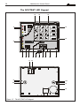
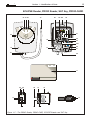
ECLIPSE Reader, PROXI Reader, SAT Key, PROXI-CARD
D
>=
D
Figure 1.5 - The PROXI Reader, PROXI-CARD, ECLIPSE Reader and SAT Key
14
Multifunction Control Panel
!
#
$%&
'$()(*+
()',(*+
%,(
24,424
, )
, *4,, )
94-, )
'
<
*
1
!
(Ö
5=5
.Ö
515
-/Ö
525
-0Ö
5>50)
2/341,2
!
',(?
"
1
?
1'2,91
(*%+7
2/3
"$%&
'$(1
(10/)
9<''
(10/)
9<''*
(10/
9<''0
(10/2)
#,2)
,#
#,2
,#0
15
Section 1 - Identification of Parts
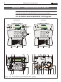
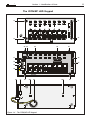
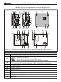
M-IN/6 Input and M-OUT/6 Output Expanders
Figure 1.6 - M-IN/6 Input Expander (a) M-OUT/6 Output Expander (b) Expander box (c)
/*//2
:: @ !
Ö::/
Ö::
A/1BC
Ö::
A/1BC
)
( '
*@ !
Ö
*
$Ö
*
D
8)
8&
!
( "
,& )+"67
*8 ,& )
1*
16
Multifunction Control Panel
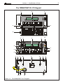
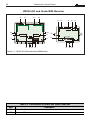
VRX32-433 and Vector/RX8 Receiver
D
D
D
Figure 1.7 - VRX32-433 (left) and Vector/RX8 Receiver
3(+"!""34(+
1
&
,
&
Section 2 - Installation
17
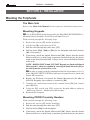
SECTION 2 - INSTALLATION
Mounting the Peripherals
The Main Unit
Refer to the Main Unit Manual for the respective installation instructions.
Mounting Keypads
A Use of ICON/KP Keypads down-grades the IMQ-SECURITY SYSTEM Certification from Performance Level II to performance Level I.
Work carefully through the following steps:
1. Remove the screws [47] and the frontplate.
2. Lift the clip [58] and remove the PCB.
3. Pull the wires through the cable entry [57].
4. Drill the holes [59a], [59b] or [59c] for the backplate and snatch bracket
[61] (if necessary).
5. If necessary, install the Snatch Microswitch [56]. Ensure that the Snatch
Microswitch lever is held firmly in position (pressed down) by the plastic
tooth on the Snatch bracket [61]. Using a screw, secure the Snatch bracket
to the wall.
NOTE - OMNIA/TAST-R and NC2/TAST Keypads are fitted with Snatch
Microswitches, which are enabled by securing the Snatch bracket [61] to
the wall by means of an anchor screw .
6.
7.
8.
9.
A In order to comply with the standards outlined in Performance Level 11
of the IMQ-SECURITY SYSTEM certification, keypads must be fitted with
Snatch Microswitches.
Replace the PCB and, if required, the Tamper Microswitch (for MIA or
ALISON Keypads), then connect to connector [50].
Complete the connections between the terminal board [53] and Control
panel BPI Bus.
Using the DIP switch strip [51], assign the Keypad Address (refer to
‘Addressing Devices’, further on in this section).
Reattach the frontplate.
Mounting PROXI Proximity Readers
Work carefully through the following steps:
1. Remove the screws [47] and the frontplate.
2. Pull the wires through the cable entry [57].
3. Drill the holes [59a] for the backplate.
4. If necessary, install the Snatch Microswitch [56]. Ensure that the Snatch
Microswitch lever is held firmly in position (pressed down) by the plastic
18
Multifunction Control Panel
tooth on the Snatch bracket [61]. Using a screw, secure the Snatch bracket
to the wall.
A In order to comply with the standards outlined in Performance Level 11 of
the IMQ-SECURITY SYSTEM certification, Readers must be fitted with Snatch
Microswitches.
5. Using the cable [70], complete the connections to the Control panel BPI
Bus.
6. Assign the Addresses to all the peripheral devices (refer to ‘Addressing
Devices’, further on in this section).
7. Reattach the frontplate.
PROXI Readers must be located at least 50 cm apart.
Mounting ECLIPSE Readers
ECLIPSE Key Readers can be flush mounted on standard electricity outlet
boxes (refer to Table 1.3).
Before mounting the Reader, complete the connections between the ECLIPSE
terminal board [53] and Control panel BPI Bus.
A In order to comply with the standards outlined in Performance Level 11 of the IMQSECURITY SYSTEM certification, Readers must be fitted with Snatch Microswitches.
ECLIPSE Readers must be located at least
50 cm apart.
Using the Address Microswitches [51], assign
the Reader Address (refer to ‘Addressing Devices’, further on in this section). For security
reasons, outdoor flush-mounted Key Readers
must be fitted with tamper protection (see Figure above).
Input and Output Expanders
The Input and Output Expanders must be located as near as possible to the
peripherals they are connected to. The Input and Output Expanders boxes can
be surface or flush mounted.
To install the Expanders:
1. Remove the Wire entry knockout ([57] or [85], as required.
2. For Surface Mounting: drill the holes for the back box and Snatch
bracket (screw locations [84] and [61] respectively).
For Surface Mounting on Mod.503 boxes or similar: drill the holes for
the back box and Snatch bracket (screw locations [83] and [61] respectively).
For Flush Mounting: No drilling is necessary.
3. Pull the wires through the wire entry.
19
Section 2 - Installation
4. Attach the back box and Snatch bracket.
5. Replace the Expander Module [80] (see Figure 1.6), ensure that it is held
firmly in place by the PCB clips [58] then, using the two screws [81], secure
it to the backplate.
6. Complete the connections on the terminal board [53].
7. Using the Microswitch [51], assign the Expander address (refer to ‘Addressing Devices’, further on in this section).
8. If necessary, remove the Jumper [78] in order to enable Tamper and Snatch
Microswitches.
9. Using the Jumper [77], set the Buzzer Mode.
10. Using the 4 screws [79], secure the frontplate to the back box.
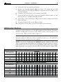
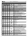
Addressing Devices
You must assign Addresses to all the BPI peripherals (Key Readers, Proximity
Readers and Keypads). For devices with 4 DIP switches, refer to Table 2.1, for
devices with 5 DIP switches, refer to Table 2.2.
You can assign the Addresses in any order, however, devices of the same type
must have different Addresses. Devices of different types (e.g. a Keypad and a
Key/Card reader) may have the same Address.
NOTE - If you are Addressing an ALISON keypad, without a DIP switch
strip, you must assign the Address in accordance with the respective instructions in this section. You can exit the programming phase and restore normal
operating mode at any point in the procedure by connecting the jumper [54].
!,55,6
7
'
0+
,
!
"
! " / / / / / / / / /0 /0 /0 /0 /0 /0 /0 /0
!
/ / / / /0 /0 /0 /0 / / / / /0 /0 /0 /0
"
/ / /0 /0 / / /0 /0 / / /0 /0 / / /0 /0
/ /0 / /0 / /0 / /0 / /0 / /0 / /0 / /0
!!,55,6
7
0+
,
!
"
! " 8
/ / / / / / / / / / / / / / / /
!
/ / / / / / / / /0 /0 /0 /0 /0 /0 /0 /0
"
/ / / / /0 /0 /0 /0 / / / / /0 /0 /0 /0
/ / /0 /0 / / /0 /0 / / /0 /0 / / /0 /0
/ /0 / /0 / /0 / /0 / /0 / /0 / /0 / /0
20
Multifunction Control Panel
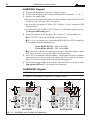
ALISON/8L Keypad
1. Remove the frontplate to generate ‘Tamper’ status.
2. Connect the Keypad to the Control panel BPI BUS (terminals +, C, R, -).
3. Remove the jumper [54]:
after several seconds the Keypad will emit an audible signal and the 4 LEDs
on the left (“A” in Figure 2.1) will turn ON;
the four pairs (up/down) of LEDs (“B” in Figure 2.1) will simulate 4 DIP
microswitches;
one of the first pair of LEDs (“B” in Figure 2.1) will blink to signal access to
the Keypad Addressing phase.
4. Assign an Address to the Keypad (“B” in Figure 2.1 shows Address 4).
Use A or B to select the LED/DIP switch position.
Use C or D respectively, to turn the RED LED ON or OFF as required,
in accordance with the following logic:
Upper RED LED ON = DIP switch ON
Lower RED LED ON = DIP switch OFF
If you wish to delete the setting and assign a different Address, press
e (the Alison/8L will step back after several seconds).
5. Press E to confirm the selected Address. The Keypad will emit an audible
signal and will go back to step 4., this will not affect the setting, but is simply
due to the circular organization of the programming process.
6. Re-insert the Jumper [54], in accordance with the BPI Level (refer to “Setting up the BPI Level”), then replace the frontplate.
ALISON/32L Keypad
NOTE - This keypad cannot be connected to the KYO16D Control Panels.
1. Remove the frontplate to generate a ‘Tamper’ status.
$/,621/
Fig. 2.1 - ALISON/8L and ALISON/32LP addressing
$/,621/3
Section 2 - Installation
21
2. Connect the Keypad to the Control panel BPI BUS (terminals +, C, R, -).
3. Remove the jumper [54]:
after several seconds the keypad will emit a beep, and the 4 LEDs on the left
(“A” in Figure 2.1) will turn ON;
the four pairs (up/down) of LEDs (“B” in Figure 2.1) will simulate 4 DIP
microswitches;
one of the first pair of LEDs will blink to indicate access to the Addressing phase.
4. Assign an Address to the Keypad (“B” in Figure 2.1 shows Address 4).
Use A or B to select the LED/DIP switch position.
Use C or D respectively, to turn the LED ON or OFF, in accordance
with the following logic:
Upper RED LED ON = DIP switch ON
Lower RED LED ON = DIP switch OFF
If you wish to delete the setting and restart, press e.
5. Press E to confirm the selected Address:
after several seconds the Keypad will emit an audible signal, and the 4 LEDs on
the right (see “C” in Figure 2.1) will turn ON to indicate access to the Proximity
Reader Addressing phase (see “D” in Fig. 2.1 for the respective LEDs).
If you DO NOT wish to use the Proximity Reader, press o. The
ALISON/32L will step back to the Keypad Addressing phase, at which
point go to step 8. in this section.
If you wish to use the Proximity Reader, go to step 6.
6. Following the instructions in step 4., assign an Address to the Reader.
If you wish to delete the setting and restart, press e.
NOTE: After deleting the setting, the ALISON/32L will step back to the
Keypad Addressing phase.
7. Once you have assigned the Keypad and Reader Addresses, press E to
confirm. The Keypad will emit an audible signal and will go back to step 4.,
this will not affect the setting, but is simply due to the circular organization
of the programming process.
8. Re-insert the Jumper [54], in accordance with the selected BPI Level (refer to
“Setting up the BPI Level”), then replace the frontplate.
ALISON/S and ALISON/DVP Keypads
1. Generate Tamper status by removing the case.
2. Connect the Keypad to the Control panel BPI BUS.
3. Remove the Jumper 54 — after several seconds the Keypad will emit an
audible signal (long beep) to indicate access to the programming phase.
4. Alison/S - Go to step 5
ALISON/DVP
Alison/DVP - Using keys A or B, select “ALISON/DVP
ALISON/DVP”, then press
E to confirm.
22
Multifunction Control Panel
Note - On first power-up the display will show: “ALISON/DVP
ALISON/DVP”.
ALISON/DVP
5. The display will show “ALISON/DVP:01
ALISON/DVP:01” or “ALISON/S:01
ALISON/S:01”.
ALISON/DVP:01
ALISON/S:01
Using C or D , select the Address (1 to 8) for the Keypad.
6. Alison/S - Press E to confirm and continue or press e to delete the
setting — in both cases the Keypad will emit an audible signal. Re-insert the
jumper 54 and replace the case, the Keypad will exit the programming
session automatically.
Alison/DVP - Press E to confirm and continue or press e to delete the
setting — in both cases the Keypad will emit an audible signal.
7. Using C or D , select an address for the Proximity Reader, the display will
show the current Address of the Proximity Reader: “PROXI: 01” (preset at
factory).
If you DO NOT INTEND using the Proximity Reader — press o, the
PROXI: OFF
display will show the “PROXI:
OFF” message.
If you INTEND using the Proximity Reader — press O, the display will
PROXI: 01
show the “PROXI:
01” message.
8. Press E to confirm, or press e to delete the setting — in both cases the
CALL
Keypad will emit an audible signal and the display will show the “CALL
SERVICE
SERVICE” message. Re-insert the jumper 54 and replace the case, the
Keypad will exit the programming session automatically.
NOTE - KYO16D Control Panels has no vocal functions.
Setting up the BPI Level
The BPI Level of the system peripherals (Keypads Readers, etc.) must match
the BPI Level of the Control panel (set by means of the Jumper [49]).
5 volt BPI Level To program the BPI Level at 5 Volt, insert Jumper [54] in the ‘BPI LEV 5V’
position, and insert Jumper [49].
12 volt BPI Level To program the BPI Level at 12 Volt, insert Jumper [54] in the ‘BPI LEV 12V’
position, and remove Jumper [49].
NOTE: NC2/TAST, ICON/KP LED Keypads and ECLIPSE Readers with 4 DIP
switches operate at +5V. Therefore, if one of these devices is included in the system,
the BPI Level of the Control panel and BPI peripherals must be set at +5V .
KYO16D - Kyo16D Control Panel work only with 12V level BPI: all BPI
devices connected to the Kyo16D must have 12V BPI level. If you want connect an OMNIA/TAST-R keypad, make sure the [49] and [54] jumpers are
present (refer to chapter 1).
Section 2 - Installation
23
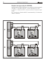
Installing the VRX32-433 and Vector/RX8 Receiver
Control panels from the 8W, 8GW, 16D, 32 and 32G series support VRX32-433
and Vector/RX8 Wireless Receivers for Wireless device management. This section describes the features and installation procedure of these devices.
The VRX32-433 Receiver manages up to 32 Wireless detectors (PIR Detectors,
Smoke Detectors and/or Magnetic contacts), and up to 16 Wireless Keys.
The Vector/RX8 manages up to 8 Wireless Zones and 16 Wireless Keys.
A Systems which are set up to manage more than 14 Wireless Keys, DO
NOT COMPLY with IMQ-SECURITY SYSTEM Performance level II certification.
Before mounting the Receiver:
z
z
z
z
Choose a safe dry place.
Select a location that will provide the best possible reception.
Locate the Receiver as high up as possible.
Do not locate the Receiver near sources of EMI (television sets, electric
motors, domestic appliances, etc.)
z Do not limit the range with large objects or furniture.
Installing the Radio Receiver (refer also to Figure 1.7)
1. For VRX32-433 - Loosen the screw [47] (it is not necessary to remove
them).
For Vector/RX8 - Remove the screw [47].
2. For Vector/RX8 only: using a screwdriver, press down on the tab [64] in
order to free the backplate from the frontplate.
3. Remove the frontplate then pull it away from the backplate.
4. Pull the connection wires through the wire entry [57], place the backplate in
the proposed placement, mark the anchor screw locations [59a].
5. Remove the backplate from its placement, then drill the screw holes (check
for plumbing and cable conduits before drilling).
6. Replace the backplate in the proposed placement, pull the wires through the
wire entry [57], then secure the backplate to the wall.
7. Complete the connections on the terminal board [53].
8. Replace and secure the frontplate with the screws [47].
Changing the batteries of Wireless Devices
If you intend changing the batteries of the Wireless Devices, you must first put
the Control panel in Service Mode by typing in the Installer Code + E, or by
using a Service Key at an Enabled Reader.
However, if your system includes any LCD Keypads, you must also access the
Installer Menu and select “Actions Ö Zone Status” (refer to “Programming” in
the “PROGRAMMING FROM KEYPAD” manual).
24
Multifunction Control Panel
Connecting Peripherals
This section describes the wiring of the peripheral devices.
Shielded conductor cable must be used for all connections. One end of the shield
must be connected to the Control panel, as shown in the wiring diagrams. Each
wiring diagrams refers to a specific device type (Keypad, Key/Card Reader,
Sensor or Signalling device) and shows the respective terminals.
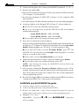
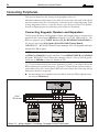
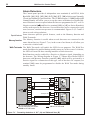
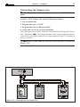
Connecting Keypads, Readers and Expanders
The Keypads, Readers and Expanders (Input and Output) must be connected in
parallel to the Control panel BPI Bus (terminals 1[+], 2[C], 3[R] and 4[–]). The
BPI bus supports up to 24 BPI devices (12 for KYO16D Control Panel) in
all, but not more than 8 Keypads (4 for KYO16D Control Panel).
IMPORTANT - KYO16D Control Panel manages all LCD keypads and only
Alison/8L LED keypad.
NOTE: For Kyo4-8-32, this Control panel does not manage Lines L1 and L2
on MIA/S and MIA/D Keypads, and Line L1 on OMNIA/TAST-R and ALISON
Keypads. KYO16D Control Panel does manage only L1 Line of LCD keypads,
but to use a 10Kohm resistor for balanced line.
11.5V or over must be present across terminals [+] and [–], in order to allow the
BPI peripherals to operate properly. Owing to Voltage drops and stray capacitance induced by the Control panel BPI bus connections, the following wiring
limitations must be respected:
the maximum wire length between the Main Unit the BPI peripheral must
not exceed 500 metres;
3
11
8.
(6&
21
2))
(; &
35 *
5( 6
Figure 2.2 - Wiring diagram: Connecting 3 Keypads to the Control panel
3907
25
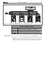
Section 2 - Installation
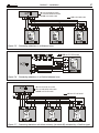
Figure 2.3 - Connecting ECLIPSE/PROXI Readers and Expanders (IN/OUT)
!"#$%&
'"#$%&
!
Wiring limitations the overall wire length for the BPI must not exceed 1000 metres.
See to Figures 2.2 and 2.3 for the Keypad, Reader and Expander wiring diagrams.
A The IMQ-SECURITY SYSTEM approval applies only when the Expander OC outputs are interfaced with relays, installed inside the Expander box.
26
Multifunction Control Panel
Alarm Detectors
The Control panel provides 8 independent zone terminals (4 on KYO4, 6 for
Kyo16D): [L1], [L2], [L3], [L4], [L5], [L6], [L7], [L8] which accept Normally
Closed and Normally Open detectors. The 10 KΩ resistors (1.2 KΩ for Kyo16D
Control Panels) will allow you to set up the zones as Balanced or Double Balanced. Resistors are not required when the lines are programmed as N.C. or N.O.
M] and Positive terminal [+B] (or [+F] on Series G models)
Negative terminal [M
can be used to power the detectors. Several detectors can be connected to each
zone, however, one detector per zone is recommended. Figures 2.4, 2.5 and 2.6
show several wiring solutions.
Special features Some detectors provide special features, such as the Memory function and
Walk-Test mode.
Memory function The Memory function is useful when several detectors are connected to the
same Alarm line (see Figure 2.7) as, in the event of an Alarm, it will allow you
to trace the violated zone.
Walk-Test mode The Walk-Test mode will enable the LED for test purposes. The Walk-Test
mode should not be enabled during standby status as, in the event of violation,
the LED will turn ON thus warning intruders of their detection.
Both functions can be enabled by a Positive or Negative signal, depending on
the detector. The Wiring diagram in Figure 2.7 shows three Bentel LB612
detectors with Memory function (terminal [AB]) which will be activated by a
Positive signal. In a connection of this type, one of the three OC outputs (see
terminal [O1]) must be programmed to disable the Walk Test mode during
standby status.
-
,
Figure 2.4 - Connecting detectors to N.C. (a) and Balanced lines (b)
27
Section 2 - Installation
Figure 2.5 - Connecting detectors to a Balanced zone
Figure 2.6 - Connecting detectors to a Double balanced zone
Figure 2.7 - Connecting detectors with Alarm memory (terminal AB) activated by a Positive signal
28
Multifunction Control Panel
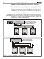
Connecting Fire Detectors (with Repeat Outputs)
This Control panel also accepts Fire detectors. The Alarm repeat outputs of the
Fire detectors must be connected to Fire zones (Normally Open -24 hour
zone).
The wiring diagram in Figure 2.8 shows three Rate-of-Rise/Smoke detectors
(e.g. Bentel’s RT-101, RT-102 and RF501t) connected to Alarm line [L1]. In a
connection of this type, the Negative signal (Reset) is supplied by the Normally Closed OC output (see [O1]).
Connecting The wiring diagram in Figure 2.9 shows a similar connection using a Relay Base.
Relay bases In a connection of this type, the Control panel OC output (see [O2]) must be
programmed as Normally Closed, and the Alarm Line ([L2]) as Balanced 10K
(‘Balanced 1k2’ for Kyo16D Control Panels).
.<2
Figure 2.8 - Connecting detectors with Repeat Outputs
.<2
23 !"#$
2 % %!"#%$
245&'$
6
$&'
Figure 2.9 - Connecting Relay Bases to a Balanced Line
29
Section 2 - Installation
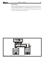
Alarm Siren
All types of signalling devices can be connected to the free-voltage relay (terminals [NC], [NO] and [COM]). The wiring diagram in Figure 2.10 illustrates the
wiring of a Self-powered Siren (e.g. ECHO99) and an Indoor Siren (e.g. Wave).
In a connection of this type, the Self-powered Siren which will activate when
the Positive signal drops on terminal [+N].
Figure 2.10 - Connecting Indoor and Self-powered Sirens
30
Multifunction Control Panel
Connecting Roller-Blind and Vibration Detectors
Zones 1 through 6 of the KYO8 and KYO32 Models, and all zones of the KYO4
(zones 1 through 2 for Kyo16D) support Roller-blind and Vibration detectors.
The zones must be programmed respectively with either the Vibration or
Roller-blind attribute (refer to the ‘PROGRAMMING FROM PC’ section in
this Manual), and can be set up as Normally Closed (N.C.) or Balanced 1.5 KΩ
(BAL). The wiring diagram in Figure 2.11 shows a typical connection. The 1.5.
KΩ (600ohm for Kyo16D) Balance Resistor must be connected to the last device, as shown in Figure 2.11.
The 1.5 KΩ Balance Resistors are not supplied.
If the system has an LCD Keypad, it will be possible to Test the sensitivity of
the ‘Vibration’ zones. The system must be put in SERVICE MODE, by
leaving a Digital Key in a Reader, or by inserting the INHIBIT ALARMS
Jumper [8] (the zones must be tested SEPARATELY). The display will show
the Test message and the ‘Shock’ value (0 through 20).
IMPORTANT - For the most reliable results, the ‘ViTest Vibrat 018
bration’ attribute must be disabled on all zones except DDIIZZZZ
the one being tested.
Figure 2.11 - Connecting Roller blind and Vibration detectors to a N.C. and a Balanced Line
Section 2 - Installation
31
Connecting the Tamper Line
G - The Tamper Line terminals [AS] are not present on KYO16D Control
Panel.
To make a 24 H Tamper Line on KYO16D Control Panel:
1. Une an alarm zone
2. Program this zone as “24 H”
3. Program this zone as “Balanced 10 K”
4. Assign this zone to one or more partitions
The Control panel (except KYO16D) has a 24h 10K Balanced Tamper line (TermiM]). The Tamper terminals of the system peripherals must be
nals 5 [AS] and 6 [M
connected in series to these terminals. The wiring diagram in Figure 2.12 illustrates a
typical connection.
10 KΩ Balance resistor must be connected to the last device, as shown in
Figure 2.12.
'(7(&725
6,5(1
Figure 2.12 - Connecting the 24h Tamper Line
32
Multifunction Control Panel
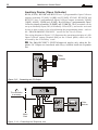
Auxiliary Device (Open Collector)
KYO4, KYO8, KYO8W and KYO32 have 3 programmable Open-Collector
outputs (terminals 23 [O1], 24 [O2] and 25 [O3]). KYO8G, KYO8GW and
KYO32G have 5 programmable Open-Collector outputs (terminals 38[O1],
39[O2], 40[O3], 41[O4] and 42[O5]). Kyo16D have 2 programmable OpenCollector outputs (terminals 22 [OC1] and 23 [OC2]). These terminals can be
set up as Normally Open (NO) or Normally Closed (NC), and can be activated
by one or more events (to be selected during the programming phase—refer to
the ‘PROGRAMMING FROM PC’ section for the list of events).
The wiring diagram in Figure 2.13 illustrates the operating principles of a NO
Open-Collector output (terminal [O1] on the Control panel) which will be
activated by the ‘Exit Delay’ event.
A The IMQ-SECURITY SYSTEM approval applies only when the Expander OC Outputs are interfaced with relays, installed inside the Expander
box.
5HOD\
&RQWDFWV
5HOq
Figure 2.13 - Connecting an OC Output
Figure 2.14 - Connecting the Telephone Line
Section 2 - Installation
33
Connecting the Telephone Line
If Telephone Dialler facility is used, the Telephone line must be connected to
terminals [LE]. In this way, the Control panel will be the first device on the
telephone line. If the Control panel is sharing the line with another device, the
latter must be connected to terminals [LI] (see Figure 2.14), thus allowing the
Control panel to take priority in the event of an Alarm.
G - Terminal [-] must be connected to the Mains Earth in order to protect
the PCB against line surges.
G - Ensure that the Mains Earth line is intact and operating properly before
connecting the telephone line.
If the Control panel is not connected to the telephone line, the Disable Telephone line check option must be activated, otherwise, the Telephone Line
Trouble event will be signalled continuously (refer to the ‘Options Page’ in the
‘PROGRAMMING FROM PC’ section).
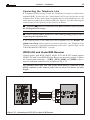
VRX32-433 and Vector/RX8 Receiver
Control panels with K8W, K8GW, K16D, K32 and K32G boards support
VRX32-433 and Vector/RX8 Wireless Receivers (accessory items). Connect
the Control panel terminals — [GRN], [YEL], [BLK] and [RED] to the respective terminals on the Receiver, as shown in Fig. 2.15.
Use Shielded cable only. One end of the shield must be connected to the
[BLK] terminal on the Control panel. Do not exceed 50 meters of cable
length.
Figure 2.15 - Connecting a VRX32-433 or Vector/RX8 Receiver
34
Multifunction Control Panel
‘Double’ line type (only for KYO16D)
The KYO16D has 6 zones connections. Each connection can be programmed
“DOUBLE” or “DOUBLE with EOL” to reach a maximum of 12 zones.
A “Double” or “Double with EOL” connection can detect 2 alarm and a single
tamper.
Fig. 2.16a shown the “Double with EOL” connection and Fig. 2.16b shown the
“Double” connection
(2/
,
.<2
'
-
.<2
'
Fig. 2.16 - Connecting the “Double Line”
Section 3 - Programming from PC
35
SECTION 3 - PROGRAMMING FROM PC
Introduction
This system can be programmed via keypad or via the ‘KyoUnit’ software
application from the Bentel Security Suite. In the latter case, the computer
must be linked to the Control panel by a serial cable (e.g. Bentel’s CVSER/9F9F).
This section holds in-detail information on the system parameters, and should
also be referred to when programming via keypad.
The programmed parameters can be saved on the computer hard disk, or on a
floppy disk, and downloaded to the Control panel via modem or on-site.
The parameters are grouped together in pages. The pages in this section follow
the page order in the ‘KyoUnit’ application.
NOTE - The images of the software are indicative and they depend on the Control
Panel version used.
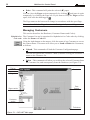
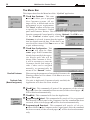
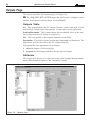
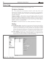
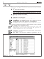
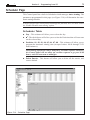
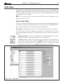
Main Window
The ‘KyoUnit’ application opens on the Main page (see Figure 3.1). The Treeview menu (see Pages section) will allow you to access all the Pages in the
Application.
Managing the Pages
Accessing the Pages Click once on the name of the required page — the page name will highlight and
the page will open, ready for programming.
Saving the Parameters Use the Save command from the File menu.
Using the right button on the mouse, click any part of the Page section to access
the context menu. The context menu will allow you to Select, Upload, Download
and Print the Pages, as follows.
z
Select - This command will select/deselect the pages. Only selected pages
) can be downloaded/uploaded/printed.
(
The Pages can also be selected/deselected via the “Ins” key on the Computer
keypad.
z
Download - This command will download the selected pages (
) to the
Control panel.
z
) to the Computer.
Upload - This command will upload the selected pages (
The pages will be deselected automatically after Downloading/Uploading.
36
Multifunction Control Panel
z
) pages.
Print - This command will print the selected (
You can close the Pages section temporarily by clicking , and open it again
temporarily by clicking the Page bar. If you want to keep the Pages section
open, click also the drawing pin .
The Page name on the button will change in accordance with the open Page.
You can show/hide the ‘Pages’ section via SettingsÖ Layout Ö Pages.
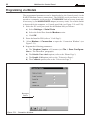
Managing Customers
This section describes the Database (Customer Names and Codes).
Alphabetical or The Customer list can be organized in Alphabetical or Code order by clicking
Code order either the Name or Code bar.
Using the right button on the mouse, click the name of any Customer to access
the context menu. This menu will allow you to Load or Delete the Customers,
as follows.
z
Upload - This command will load the Customer Configuration page.
You can also upload the Customer’s data by double clicking the Customer’s
name on the Customer list.
z
Delete - This command will allow you to delete the selected Customer from
the Customer list, and consequently from the Database (see Figure 3.2).
Title bar
Menu bar
Close button
Page bar
Pages section
Data
Section
Customers
section
Toolbuttons
Figure 3.1 - KYO UNIT Main page
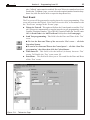
Section 3 - Programming from PC
37
Figure 3.2 - Deleting Customers window
You can close the Customers section by clicking , and show/hide the Customers section via Settings Layout Pages, or by pressing F9 on the
computer keypad.
Data Section
The pages you select from the Pages section will be shown in this part of the
Main window.
Toolbar and toolbuttons
The Main window (see Figure 3.1) provides the following bars and tools.
z
Title Bar — this bar will show the selected Customer’s name;
z
Toolbuttons — these buttons will download/upload the current Page;
z
Menu Bar — this bar is similar to the Menu bars of most WindowsTM programs, and will allow you to access basic functions, such as: New Customer,
Serial Ports, etc. The Menu bar options are described in the ‘Menu Bar’ paragraph.
z
The Close Application button.
You can also close the Application via File Ö Exit.
Upload, Download and Help toolbuttons
There are 3 toolbuttons at the bottom of the Parameter Pages (5 at the bottom of
the ’Logger Page‘ and 6 at the bottom of the ’Events Page‘). The toolbuttons
are not shown on the Main window.
Upload — this button will upload the parameters of the current Page (from
Control Panel to Computer).
Download — this button will download the parameters of the current Page
(from Computer to Control panel).
Help — this button will open the context window (Adobe® Acrobat® Reader™
required).
38
Multifunction Control Panel
The Menu Bar
This chapter describes the Menu bar of the ‘KyoUnit’ application.
File New Customer - This command will allow you to program
New Customer systems. All settings will be at default and can be
programmed as per requirements.
The ‘Panel’ window will allow you
to specify the Customer’s Control
panel and Firmware Release. This information can be uploaded directly
from the connected Control panel by clicking Upload. Click OK to exit.
If the ‘Confirm’ window opens, when New
Customer is selected, it means that the Application has found unsaved data. If the data is not
saved it will be cleared. Click Yes to save or ‘No’
to quit without saving.
File Save Configuration - This
command will open the ‘Customer’ page. If the Customer has
already been enrolled, the respective details and Code will be
shown. If the Customer is ‘New’,
it will be necessary to enter the
Customer details and assign a
code. Codes can be assigned
manually, or automatically by
means of the “Search” button.
Enrolled Customer
When saving the parameters of an enrolled Customer, the
Warning window will be shown. Click Yes to save new
data or No to quit.
Duplicate Code
(Manual assignment)
If a code is duplicated (Customer already enrolled) the
Application will show the Error window.
File Print - This command will print all the parameters of the selected
). Once the command has been executed, all the selected pages (
)
pages (
will be deselected automatically.
File Exit - This command will close the Application.
Programming Upload - This command will transfer all the programmed
data from the Control panel to the Computer. Once the command has been
) will be deselected automatically.
executed, all the selected pages (
Programming Download - This command will transfer all the programmed data from the Computer to the Control panel. Once the command
) will be deselected automatihas been executed, all the selected pages (
cally.
Section 3 - Programming from PC
39
Settings Layout - This option will allow you to view/hide the Pages and
Customers sections.
Settings Serial Ports - This option will allow
you to setup two Computer COM Ports, for the
connections between the Control panel and Modem (via RS232 link). It will also allow you to
program the maximum number of connection attempts (5 at default), and the maximum bytes in a
single frame during remote transmission (64 at default). Poor quality transmission can be improved
by reducing the number of transmission bytes.
Settings Language - This option will allow you
to select the Application language. Click the required language then the OK button.
Settings Print Setting - This window will allow
you to create the letterhead for the printout.
To attach a picture or Logo to the letterhead: click Logo and select the path
of the Bitmap (.BMP extension).
NOTE - Once the picture or Logo has
been attached to the letterhead, DO NOT
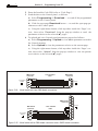
delete or move it from the Hard-Disk.
Settings Panel - This command will allow you to specify the Customer’s
Control panel and Firmware Release (refer
to File New Customer). If you make a
Download/Upload request, and the data in
the ‘Panel’ window does not match the
connected Control panel, the Application
will show the ‘Confirm’ window. Click Yes to confirm the Download/Upload
request, or No to quit. In both cases, the Application will be updated automatically with the new Control Panel Type and Firmware release.
Settings LCD Strings This command will allow
you to select the Language
for the LCD Keypads (refer
to “Available language on
the software”): after selecting the Language, click the Download button (bottom left) in order to
update the Control panel. KYO 32 Series Control panels also provide the
“Available language on the panel” option, which will allow you to Upload
or Download one of the 4 resident languages on the Control panel board.
Click OK to exit.
Settings Conversion table - This command will allow you to create a
alternative character table to WindowsTM (e.g.Cyrillic), or to customize the
current table.
40
Multifunction Control Panel
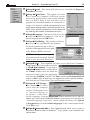
Check System enquiry and control - This command will open a window
similar to the one shown in Figure 3.3. which will allow you to:
z View the status of the Partitions
z View the status of the Zones
z View the status of the OC Outputs, and the Alarm Outputs
z View Trouble and Tamper events
z Arm/Disarm Partitions
z Bypass/UnBypass Zones
z Turn ON/OFF OC Outputs
z Reset Alarm/Reset Alarm Memory
z Reset Alarm Memory
You can access all the System Enquiry options without entering a Code,
however you must enter a Main User Code to access the System Control
options (Arm/Disarm, Bypass/UnBypass Zones, Reset Alarm/Reset
Alarm Memory and Reset Alarm Memory). If the entered Main User
Code is not Enabled on the Partitions involved in the requested operation,
the commands will have no effect.
Following is a description of the ‘System Enquiry and Control’ window:
Zones - This section provides the following information for each of the
Control panel Zones:
No. - Identifier number
Description - Zone Label
Part. - Enabled Partitions
Al. - GREEN Zone in Standby; RED Zone in Alarm;
RED BLINKING Alarm in Memory
Figure 3.3 - System enquiry and control window
Section 3 - Programming from PC
41
Tam. - GREEN Zone in Standby; AMBER Tamper on Zone;
AMBER BLINKING Tamper in Memory
Byp. - GREEN Zone Unbypassed; AMBER Zone Bypassed
To Bypass/Unbypass a Zone - Using the left button on the mouse, select
the Zone then click the right button and select the required option from
the Pop-up menu. This command can be sent ONLY when the Zone is
Enabled on a Disarmed Partition.
Partitions - This section provides the following information for each of
the Control panel Partitions:
No. - Identifier Number
Description - Partition Label
Al. - GREEN All the zones of the Partition are in Standby
RED At least one of the zones of the Partition is in Alarm
Status - This column indicates the Arming mode of the Partition (refer
to table 3.1).
To Arm/Disarm a Partition: using the left button on the mouse, select
the Partition then click the right button and select the required option
from the Pop-up menu.
Tamper - This section indicates current Tamper conditions:
GREEN No Tamper; RED Tamper present
Trouble - This section indicates current Trouble conditions:
GREEN No Trouble; RED Trouble present
Outputs - This section indicates the current status of the OC Outputs:
GREEN Output in Standby; RED Output Active
To turn ON/OFF an Output: using the left button on the mouse, select the
Output then click the right button and select the required option from the
Pop-up menu. This applies ONLY to Outputs which have been set up for
“Remote Command” (refer to the ‘Output Page’).
Tamper in memory and Siren - This section indicates the current
status of the ‘Tamper Memory’ and ‘Siren’:
Tamper in memory RED Tamper events in Memory
Siren RED The Alarm Output (or Output relay) is Active
Reset Alarm Memory or Reset Alarms - You can reset the Alarm
memory or stop ongoing Alarms by means of the
button. For further
information, refer to the relevant paragraph in the USER MANUAL.
Press the Close button (
session.
)to exit the System enquiry and control
42
Multifunction Control Panel
Check Key programming - This
option will allow you to program
the system Keys/Proxi-Cards.
Once the Key/Proxi-Card has been
properly programmed and assigned to its respective Partitions,
it must be enrolled on the system.
To enrol the Key/Proxi-Card: insert the Key into the Reader slot or
hold the Proxi-Card near the sensitive area of a Proxi-Reader. The 3 LEDs on the Reader will blink to confirm
enrolment, and the computer will emit an audible confirmation signal (beep).
Check
View Configuration - This
option will
allow you to
view the system peripheral devices.
Each device
type is identified by a
colour (see
Table).
&RORXU
:+,7(
'HVFULSWLRQ
5('
%/8(
<(//2:
*5((1
Section 3 - Programming from PC
43
Modem Connection - This option will allow you to connect, via Modem,
to the remote Control panel.
Modem Setting - This option will allow you to setup the Modem.
Modem Hang up - This option will allow you to end telephone communications.
For further information on the Modem menu options, refer to “Programming from PC via Telephone”.
Help Guide - This option provides the System guide (Adobe® Acrobat®
Reader™ required).
44
Multifunction Control Panel
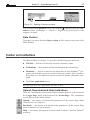
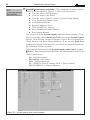
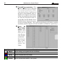
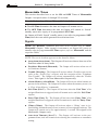
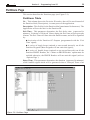
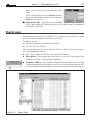
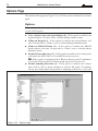
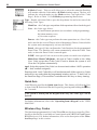
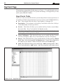
Keypads Page
At default or after a restoration Factory preset, in the Control Panel are automatically programmed one or more keyboards according to as specified in Tab.
6.1 of the Chapter 6 of MAIN UNIT MANUAL.
Keypads Table
This table will allow you to enable (
) or disable (box empty) the system
keypads.
No. - This column shows the keypad Address (non editable).
Description - This field is for the keypad label (maximum 16 characters).
The number next to the Page Name indicates the total number of enabled keypads.
Enable Keypad
) or disable (box empty) the keypad on
This section will allow you to enable (
the partitions.
Keypad Type
This section will allow you to specify the type of keypad (refer to Chapter 2).
Select LCD for MIA, ALISON/S, ALISON/DVP and OMNIA/TAST-R
keypads.
Figure 3.4 - The Keypads Page
Section 3 - Programming from PC
45
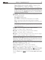
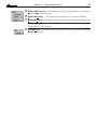
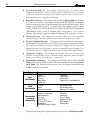
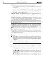
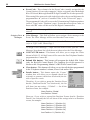
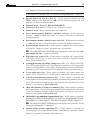
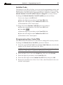
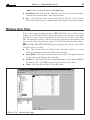
Readers Page
The Card/Key Readers will allow you to perform all basic operations, such as:
Global Arming
Disarm Partitions
A Mode Arming
B Mode Arming
Stop Alarm on Partitions
Readers Table
This window will allow you to enable (
) or disable (box empty) the system
Readers (see Figure).
No. - This column shows the Reader Address (non-editable).
Description - This field is for the Reader label (maximum 16 characters).
1 2 3 4 5 6 7 8 - These columns correspond to the 8 partitions. The Readers can
be programmed to operate in 3 different modes on the 4 partitions, as follows.
RED - This row will allow you to enable (
) or disable (box empty) the
Reader for GLOBAL Arming on the selected partitions (see Figure). All the
enabled partitions will arm, when the PROXI CARD/Key is removed from
the Reader when the RED LED is ON.
) or disable (box empty) the
AMBER - This row will allow you to enable (
Reader for A Mode Arming on the selected partitions. The partitions will
Arm or Disarm, as programmed, when the PROXI CARD/Key is removed
from the Reader when the AMBER LED is ON. Refer to table 3.1 for the
A Mode programming instructions.
Figure 3.5 - Readers Page
46
Multifunction Control Panel
",-9,15
&
,
,
,7
(
,7 .
.
E
*
*)
'
'
(
.
.
)
*E
*
*)
' (
1
:
:%5
(
(
)
) or disable (box empty) the
GREEN- This row will allow you to enable (
Reader for B Mode Arming on the selected partitions. The partitions will
Arm or Disarm, as programmed, when the PROXI CARD/Key is removed
from the Reader when the GREEN LED is ON. Refer to table 3.1 for B
Mode programming instructions.
The number in brackets at the side of the ‘Page’ type (Readers), indicates the
total number of enabled Readers.
Receiver Page
This page will allow you to select the
type of Receiver you are using:
VRX32-433 or Vector/RX8.
The receiver Vector/RX8 manages only 8 Wireless Zones. If this receiver is used
on a Kyo16D Control Panel or on one of the Kyo32 Series Control Panels, only
the zones from 9 through 16 can be programmed as “Wireless”
Section 3 - Programming from PC
47
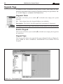
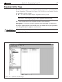
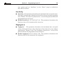
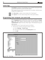
Expander In/Out Page
KYO32 Control panels accept 4 M-IN/6 Input Expanders and 2 M-OUT/6
Output Expanders. This page (see Figure 3.6) will allow you to Enable/Disable
the expanders on the system.
z
- To enable the Input/Output Expander on the system.
If the Expanders are enabled, the number of Inputs and/or OC outputs in
‘the Zones’ and ‘Outputs’ pages will be updated automatically.
No. - This column shows the Expander Address (non-editable).
Description - This field is for the Expander label (maximum 16 characters).
All other Control panels of the KYO series are unable to accept Expanders,
even though the option appears on the menu.
The number next to the Page Name shows the total number of enabled Expanders (Input and Output).
Figure 3.6 - Expander In/Out Page
48
Multifunction Control Panel
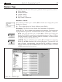
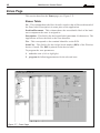
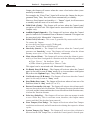
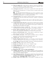
Zones Page
This section describes the Zones page (see Figure 3.7).
Zones Table
No. - This column shows the Zone identifier number that will be used instead of
the Zone label (Description) in some parts of the application.
Position/Placement - This column shows the non-editable label of the hardware component the zone is assigned to.
Description - This field is for the keypad label (maximum 16 characters). The
Application will use the label as the zone identifier.
Ter. - This corresponds to the terminal identifier on the PCB.
Serial No. - This field is for the 6 digit Serial number (ESN) of the Wireless
device (if used). The ESN is printed on the device label .
To program the zone parameters:
1. select the zone (click to highlight);
2. program the following parameters for the selected zone.
Figure 3.7 - Zones Page
Section 3 - Programming from PC
49
Type
This section describes how the various Zone types respond to violation during
Standby status (Unbypassed). Bypassed zones will ignore violation and will not
generate Alarms.
(...) In this section, the text in brackets ( ... ) refers to the text which will actually
appears on the LCD Keypad.
Alarm Zones z Instant (Instant) - Violation of this type of zone will generate an Instant Alarm.
z
Delayed (Delayed) - Violation of this type of zone will not generate an
Alarm during the Exit Time. Violation during Armed status (after the Exit
Time has elapsed) will generate an Alert signal (Entry-Time signal). If the
system is not disarmed before the Entry-Time elapses, the zone will generate an Alarm.
z
Path (Path) - If this type of zone is the first zone to be violated, it will
generate an Instant Alarm. Path zones will not generate Alarms during
Entry and Exit times.
z
24 h (24 hours) - This type of zone will always be active, regardless of the
Armed/Disarmed status of its Partition. Violation will generate an Instant
Alarm.
z
Duress (Duress) - This type of zone is automatically programmed as a
Silent 24h zone. Duress zones activate the Communicator only, and are
suitable for Panic buttons.
z
Fire (Fire) - This type of zone is automatically programmed as a 24h N.O.
(Normally Open) zone.
Command Zones z Switching (Switch.) - This type of zone is automatically programmed as
a ‘Command Zone’. Violation of this type of zone will switch the status of
all the Partitions it is assigned to (from Away to Stay Arming or viceversa).
z
Arm (Arm Only) - This type of zone is automatically programmed as a
‘Command Zone’. Violation of this type of zone will Arm all the Partitions
it is assigned to.
You cannot assign any attributes to ‘Command Zones’ (refer to the ‘Attributes’
section).
A The IMQ-SECURITY SYSTEM approval applies only when command
zones are dedicated to command devices with the same Performance level as the
Control panel which houses the decoding circuit.
Balancing
z
Double Balancing (DBAL) - In Standby status, the zone must be connected to Negative by two 10KΩ resistors (for Kyo16D the value of this
resistors is 1.2Kohm). If one of the resistors disconnects, the Control panel
will generate a Zone Alarm. In all other cases (Zone Open) the Control panel
will generate a Tamper event. This Type of connection (by means of just 2
50
Multifunction Control Panel
wires) will signal open Alarm/Tamper contacts.
z
Balance 10k (BAL) - (Balance 1k2 for Kyo16D) In Standby status, the
zone must be connected to Negative by a 10KΩ (or 1.2Kohm for
Kyo16D). For ‘Vibration’ or Roller Blind’ zones attribute, the resistor is
1.5KΩ (or 600 ohm for Kyo16D). If the resistor is short-circuited, the
Control panel will generate a Tamper Alarm. If the resistor disconnects
(Zone Open), the Control panel will generate an Alarm event.
z
Normally Closed (NC) - In Standby status, the Zone must be connected
to Negative. The Control panel will generate an Alarm when the contact
opens.
A If Zones are programmed as Normally Closed, the Performance level
of the Control panel will down-grade from Level II to Level I — as the Zones
concerned will not be protected against short-circuit.
z
Normally Open (NO) - In Standby status, the zone must be Open. The
Control panel will generate an Alarm when the Zone connects to Negative.
A The IMQ-SECURITY SYSTEM Certification does not apply when
Zones are programmed as Normally Open, as the zones concerned will not
be protected against wire cutting.
z
Doubled (Only for KYO16D) - This balance type is used to double the
zone. In this way every line (from L1 to L6) can manage two different
devices (for example, 2 sensors or 1 sensor and 1 contact) and the Control
Panel is able to recognize the one or the other in case of alarm.
z Doubled EOL (Only for KYO16D) - As the precedent, but it needs a series
End-Line (EOL) resistor of 1.2 Kohm to detect short circuits.
Attributes
z
Unbypassable (Not Byp.) - Zones with this attribute cannot be bypassed.
z
Chime (Chime) - Violation of a zone with this attribute, during Disarmed
status of its Partition, will generate an audible signal on Keypads and
PROXI readers with the ‘Chime’ attribute (refer to ‘Chime on Keypad’ and
‘Chime on Proxi Reader’ on the ‘Options’ page). Violation of a ‘Chime’
zone, during Armed status of its Partition, will not generate an audible
signal.
z
Test (Test) - Zones with this attribute will be operative, however, violation
will not activate the audible-visual signalling devices or the Communicator
but will be recorded in the event buffer. Zones with this attribute will
always operate as “Instant” Zones, even if they have been programmed as
“Delayed” Zones.
z
Mute (Mute) - Violation of a zone with this attribute will activate the
Communicator only. The audible-visual signalling devices and the keypads
and PROXI Readers will remain silent.
z
Internal (Internal) - Zones with this attribute will be bypassed when
their Partitions are armed in ‘Stay’ mode (S) or ‘Stay 0 Delay’ (I).
Section 3 - Programming from PC
z
51
Vibration (Vibrat.) - This attribute must be assigned to Zones used for
Vibration detectors. There are two trimmers for sensitivity adjustment in
the ‘ Sens. Vibration’ section.
Sensitivity: This trimmer sets the ‘Single Shock’ threshold. The selected value — minimum 20 (100 ms), maximum 1 (5 ms) — will determine
the ‘Shock’ impact the zone will allow before signalling violation. Set 1 for
maximum sensitivity.
Pulse: This trimmer sets the ‘Pulse’ threshold. The selected value will
determine the number of ‘Shocks’ the zone will allow before signalling violation. Therefore, if the trimmer is positioned on Disable, the corresponding zone will be completely insensitive to Pulses.
For example, a zone with the ‘Sensitivity’ threshold of 10 and ‘Pulse’ threshold of 5 will generate an Alarm when:
a) it receives a single Pulse that exceeds the Sensitivity threshold of 10;
b) it receives 5 Pulses of low Sensitivity within 30 seconds.
NOTE: If you assign N.C. Balancing (Normally Closed) to a Vibration
Zone, Wire cutting will not be signalled.
z
Roller Blind (Roll.Bl.) -This attribute must be assigned to Zones used for
Roller blind contacts. There are two trimmers for sensitivity adjustment in
the ‘Roller Blind’ section.
This trimmer regulates the ‘Pulse’ threshold (1 through 5). The
selected value will determine the number of ‘Shocks’ that the zone will allow
before signalling violation. Therefore, if Disable is selected, the corresponding zone will be completely insensitive to Pulses.
Pulse:
Time
- This trimmer regulates the ‘Time’ window. The selected value
will determine the ‘Pulse’ threshold time (i.e. the time allowed for the Pulse
counter to reach the programmed threshold).
For example, a zone with a ‘Pulse’ threshold of 4 and a ‘Time’ window of 2 minutes,
will signal violation when its contact generates 4 Pulses within 2 minutes.
If less pulses than the programmed ‘Pulse’ threshold are generated during
the ‘Time’ window, the zone will not signal violation, but will refresh the
window and carry forward the memorized number of pulses minus one (e.g.
3 pulses memorized = 2 pulses carried forward). The window will be refreshed until there are no pulses to carry forward, at which point, the ‘Pulse’
threshold and ‘Time’ window will reset.
If the trimmer is positioned on ‘repetitive’, the number of pulses (if less
pulses than the programmed ‘Pulse’ threshold) will be stored indefinitely.
In all cases, the ‘Pulse’ threshold will reset automatically each time the
Control panel disarms.
NOTE: Tamper cannot be signalled if N.C. Balancing (Normally Closed) is
assigned to the Roller Blind Zone.
52
Multifunction Control Panel
The ‘Vibration’ and ‘Roller Blind’ attributes can be assigned to the first
6 Control panel zones only (all zones for Kyo4 and only on the first 2
zones for Kyo16D).
z
Wireless (Wireless) - (Only for 8W, 8GW, 16D, 32 and 32G models).
Only systems with a duly enabled VRX32-433 or Vector/RX8 Receivers
(refer to ‘Options’ in this section) can manage zones with this attribute.
The 6 digit Serial Numbers of devices connected to these zones must be
specified in the respective column. If a zone is setup as a Wireless zone,
the Supervisory attribute will be enabled automatically (refer to ‘Supervisory’), and it will be shown in red.
IMPORTANT - If the “Low Battery” fault warning persists after the
batteries have been changed, deselect the “Wireless” attribute of the
respective zone then re-select it immediately.
z
Supervisory (Superv.) - If a zone is setup as a Wireless zone, this attribute will be enabled automatically, thus allowing the VRX32-433 or Vector/
RX8 Receiver to monitor the Wireless device that is connected to the zone
(refer to ‘Supervisory Time’ on the ‘Partitions’ page). If the Wireless device
fails to send a signal to the VRX32-433 or Vector/RX8 Receiver within the
programmed Supervisory window, the Control panel will generate a ‘Missing Device’ event.
The Identifier number of the zone which generated the event will be
recorded in the Event logger.
z
Double (Double P) - A Zone with this attribute will generate an Alarm if it
is violated twice within the programmed time (accepted values: 0 through
250 seconds). Refer to the ‘Double Pulse’.
z
Or (Or) - Violation of a Zone with this attribute will generate an Alarm
even when only ONE of its Partitions is Armed.
z
And (And) - Violation of a Zone with this attribute will generate an Alarm
only when all the ‘And’ Zones of the Partition concerned are violated
within the programmed Time (refer to ‘T. And Zone’ on the Partitions
page).
Cycles
This parameter determines the number of times the zone will signal the ‘Zone
Alarm’ event.
z
Repetitive (RP) - Zones with this attribute will generate the ‘Zone Alarm’
event for an unlimited number of times.
z
Cycles (Cycles) - The required number of Alarm cycles (0 through 14) can
be programmed in this field. If zero (0) is programmed, the zone will be
unable to generate Zone Alarm event.
Section 3 - Programming from PC
53
NOTE: Zones that signal persistent Alarm status (e.g. due to Trouble) will
generate One Alarm Cycle Only.
Double Pulse
This section describes how to program the Double Pulse time (0 to 250 seconds).
Partitions
This section will allow you to assign the Zones to the Partitions. The Zone will be
able to generate Alarm events only when all its Partitions are armed.
54
Multifunction Control Panel
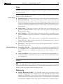
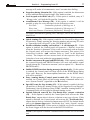
Outputs Page
This section describes the Outputs page (see Figure 3.8).
A The IMQ-SECURITY SYSTEM approval applies only if Outputs which
activate Alarm devices such as Sirens, are not Bistable.
Outputs Table
No. - This column shows the OC Output identifier number that will be used
instead of the Output label (Description), in some parts of the application.
Position/Placement - This column shows the non-editable label of the hardware component the OC Output is assigned to.
Ter. - This corresponds to the terminal identifier on the PCB.
Description - This field is for the keypad label (maximum 16 characters). The
Application will use the label as the OC Output identifier.
To program the zone parameters of an Output:
1. select the Output (click to highlight);
2. program the following parameters for the selected Output.
Attributes
This section will allow you to select the status of the Outputs during standby
status: NO (Normally Open) or NC (Normally Closed).
Figure 3.8 - Outputs Page
Section 3 - Programming from PC
55
Monostable Times
This section describes how to set the ON and OFF Times of Monostable
Outputs. Accepted values: 0 through 250 seconds.
To used this function, click on "Monostable" check-box.
The ON Time determines the time an Output will remain active.
The OFF Time determines the time an Output will remain in ‘forced’
standby status after expiry of its programmed ON Time.
An Output will hold ‘forced’ standby status (even after its programmed OFF
Time) until the event which generated its activation clears.
Signals
NOTE: The ‘Restoral’ conditions described in this section refer to ‘NONMonostable’ Outputs. Under normal circumstances, an Output will restore to
standby when its programmed ON Time expires (refer to ‘Monostable’ and the
respective Table)
NOTE: The text in brackets appears on the Installer Menu.
z
Away Arm (Away Arm) - The Output will activate when at least one of its
Partitions arms in Away mode.
z
Partitions Disarmed (Disarmed) - The Output will activate when one of
its Partitions disarms.
z
Trouble (Warning) - The Output will activate when a Trouble event occurs
(refer to the ‘Events Page’ section), with the exception of the ‘Telephone
Line Trouble’. The Output will restore automatically when the Trouble
clears. This signal is for Non-Monostable Outputs only.
z
Alarm Memory (AlarmMem) - The Output will activate when Alarms are
present in the memory. The Output will restore when the memory resets (via
a ‘Clear Alarm Memory’ command).
z
Exit Time (Exit T.) - The Output will activate when the ‘Exit Time’ of its
assigned Partitions is triggered, and will remain active until the ‘Exit Time’
expires.
z
Entry Time (Entry T.) - The Output will activate when ‘Entry Time’ of its
assigned Partitions is triggered, and will remain active until the ‘Entry Time’
expires.
z
Chime (Chime) - The Output will activate when a ‘Chime’ zone is violated during disarmed status of one (or more) of its assigned Partitions. The
Output will remain active for approximately 1 second. This signal is for
Monostable Outputs only.
z
Auto-Arm Timeout (Alert T.) - The Output will activate at the programmed time, and will remain active during the countdown to automatic
arming.
56
Multifunction Control Panel
z
Line Trouble (Line T.) - The Output will activate for 15 minutes when
telephone-line trouble is detected. If the trouble condition clears, the Output
will restore automatically when the 15 minute interval expires, otherwise, it
will remain active for a further 15 minutes.
z
Reset Fire (Fire res) - The Output will activate in Monostable mode each
a ‘Clear Alarm Memory’ operation is requested (PIN required) at a Keypad
which is assigned to one of the Partitions associated with the Output. If the
Output is programmed as N.C., it can be used as the Negative power supply
to the Fire detectors. In fact, the Negative signal will fail for the programmed
‘Monostable Time’ (refer to Outputs Page) each time a ‘Clear Alarm
Memory’ operation is requested, thus allowing the Fire detectors to reset.
z
Alarm (Al.r.bel) - The Output will activate when one of its assigned
Partitions signals Alarm, and will restore when the Alarm cycle ends.
z
Remote Command (Remote) - The Output will activate when the User executes
a command over the phone (the Control panel Answering device must be enabled).
This signal can be used to activate or stop the OC Output over the phone. The
Output (activated over the phone), can also be restored from the Keypad (via a
‘Clear Alarm Memory’ command). Refer to the User Manual for further details.
z
Negligence (Neglig.) - The Output will activate when the Control panel
generates a Negligence event, and will restore when the Alarm memory
resets (via a ‘Clear Alarm Memory’ command).
z
Monostable (Monosta.) - The Output will remain active until the ON
Time expires, after which it will be forced to standby for the programmed
OFF Time. The following Table shows the restrictions associated with
Outputs with this attribute.
*:&;
9
:*:
9
9
:*:
9
!
!
'!
'
! ()
(
!*!
%
%+
'5
"#
"
$
$
%
%!
&
,
-
#
.
/'-
/'-
If you associate any of the signals in the last section to a ‘NON Monostable’
Section 3 - Programming from PC
57
Output, the Output will restore when the cause of activation clears (automatically or manually).
For example, the “Entry Time” signal will activate the Output for the programmed Entry Time, then will restore automatically to standby.
However, if an Output is activated by a “... Tamper” signal, it will not restore
to standby until the cause of its activation clears.
z
Valid Code (Code) - The Output will activate when the Control panel
recognizes a Valid Code. This signal can be associated with ‘Monostable’
Outputs only.
z
Audible Signal (Squawk) - The Output will activate when the Control
panel is Armed via a Command Zone or Remote Command. This signal can
be associated with ‘Monostable’ Outputs only.
z
Failed Call (Fail com) - This event is generated by unsuccessful calls.
To restore the Output:
a) view the Event logger on an LCD Keypad;
b) view the Trouble on an LED Keypad.
z Inactivity (Inactiv.) - The Output will activate when the Control panel
generates an ‘Inactivity’ event. The Output will restore when the Alarm
memory resets (via a ‘Clear Alarm Memory’ command).
z
Mute Alarm (Silent) - The Output will activate when the Alarm is generated by a Zone that is assigned to a Partition with the following attributes:
a) Type ‘Duress’, b) Attribute ‘Mute’ or
c) If the Alarm is generated by a ‘Duress’ Code.
This signal can be associated with ‘Monostable’ Outputs only.
z
No Ready Stay (N.R.Stay) - The Output will activate when the Control
panel is not ready to arm in ‘Stay’ mode (S) or, in accordance with Option
52 (refer to the Options Page), ‘Stay 0 Delay’ mode.
z
Not Ready Away (N.R.Away) - The Output will activate when the Control
panel is not ready to arm in ‘Away’ mode.
z
Stay Mode (Stay Arm) - The Output will activate when at least one of its
Partitions Arms in ‘Stay’ mode (‘S’ or ‘0’).
z
Restore if on standby (Al.r.zon) - The Output will activate when Alarm conditions are detected on one of its Partitions. The Output will restore when the Alarm
cycle ends, and the Alarm conditions have been cleared from all the Partition zones,
or when the Partition disarms.
z
False key (FalseKey) - The Output will activate when an attempt is made
to use a False Key. This is real-time event, therefore, the Output cannot
restore until the False key has been removed.
z
Zone Tamper (ZoneTamp) - The Output will activate when Zone Tamper
conditions are detected, and will remain active during the respective Alarm
cycles.
z
System Tamper (Sys Tamp) - The Output will activate when violation is
detected on the 24h Tamper line, or when the Control panel is forced open.
58
Multifunction Control Panel
The Output will restore automatically when the Alarm cycle ends.
BPI Tamper (BPI Tamp) - The Output will activate when Keypad tamper
is detected (when the keypad, PROXI or Expander frontplate is removed).
The Output will restore automatically when the Alarm cycle ends.
z Valid Key (Key) - The Output will activate when the Control panel recognizes a valid Key/Card, and will remain active until the ON Time expires.
This signal can be associated with ‘Monostable’ Outputs only.
z
z
Missing BPI (Missing) - The Output will activate when an enrolled BPI
device fails to respond to the Control panel.
z
Superkey 2 (Key 2) - The Output will activate when the ‘Superkey 2’
facility is requested via Keypad. This signal can be associated with
‘Monostable’ Outputs only.
z
Superkey on wireless key (Key2 WLS) - The Output will activate when
the ‘Superkey 2’ facility is requested via Wireless Key. This signal can be
associated with ‘Monostable’ Outputs only.
Partitions
This section will allow you to assign the Outputs to the Partitions. The Output
will activate when the programmed signal is generated by one of its Partitions.
When the signal is generated by the Control panel (e.g. Trouble), the Output
will activate directly, and its Partitions will not be influent. In all other cases,
the Output will activate only when the signal is generated by one of its Partitions.
Section 3 - Programming from PC
59
Partitions Page
This section describes the Partitions page (see Figure 3.9).
Partitions Table
No. - This column shows the Partition ID number that will be used instead of
the Partition label (Description), in some parts of the application.
Description - This field is for the Partition label (maximum 16 characters). The
Application will use the label as the Partition ID.
Exit Time - This parameter determines the Exit delay time (expressed in
minutes). Violation of ‘Delayed’ Zones during the Exit time will not provoke
Alarms. The Exit Time will start when the Partition arms, and will be signalled
by:
Activation of the Partition OC Outputs (programmed with the ‘Exit
Time’ signal);
A series of single beeps (emitted at one-second intervals) on all the
Partition Keypads (Mute keypads will not emit this signal);
A series of double beeps (emitted at one-second intervals) on all the
Partition PROXI Readers, the ‘Chime on PROXI Reader’ option must be
enabled otherwise, the PROXI Readers will not emit this signal (refer to
‘Options Page’).
Entry Time - This parameter determines the duration (expressed in minutes)
of the Audible signal which will be generated when a ‘Delayed’ Zone of an
Figure 3.9- Partitions Page
60
Multifunction Control Panel
Armed Partition is violated. The Entry Time will be signalled by:
Activation of the Partition OC Outputs (programmed with the ‘Entry
Time’ signal);
A series of fast beeps, emitted by the Partition Keypads (except Mute
keypads), and Partition PROXI Readers (the ‘Enable buzzer on PROXI
Reader’ option must be active, otherwise, the PROXI Readers will not emit
this signal — refer to ‘Options Page’).
Auto-arm Timeout - This parameter (expressed in minutes) determines the
time between the Auto-arm Timeout signal and the Partition Auto-arming
event.
Example: If the scheduler is programmed to Arm the Partition at 17:30, with a
15 minute Auto-arm Timeout, the ‘Auto-arm Timeout’ will be generated at
17:15. This signal can be used to activate one of the OC Outputs.
The ‘Auto-arm Timeout’ signal will cease when the Partition Arms, or when an
Overtime Request is made.
T. And Zone - This parameter determines the time within which 2 or more
‘AND’ Zones must detect violation before the Control panel will generate an
Alarm (accepted values: 0 through 945 seconds by automatic step 15).
A The IMQ-SECURITY SYSTEM approval applies only when the " T. And
Zone" value is 30 seconds or more.
T. And Code - This parameter determines the time within which 2 or more
‘AND’ Codes must be entered before the Control panel will Disarm (accepted
values: 0 through 250 seconds).
Times
z
Patrol Time - This parameter determines the time between disarming for
patrol purposes (Patrol code required) and automatic rearming. The programmed patrol time is valid for all Partitions (accepted values: 0 through
63 minutes).
z
Alarm Time - This parameter determines the duration of the Alarm cycle
(accepted values: 0 through 63 minutes).
If the Alarm Time is set at 0 (zero), the Alarm Outputs (e.g. Siren) will not be
activated, however, the event will be sent to the Logger.
z
Supervisory window - This parameter determines the time within which a
Wireless zone must send a supervisory signal (accepted values: 120
through 1440 minutes — in steps of 15 minutes). Use the computer mouse
or the and keys on the PC keyboard to enter this value. This field will
be inactive when the ‘Enable Wireless Receiver’ option is disabled (refer to
‘Options’ page).
A The IMQ-SECURITY SYSTEM approval applies only when the
Wireless Supervisory Time is set at 2 hours 30 minutes and the ‘Supervi-
Section 3 - Programming from PC
61
sory’ option (refer to “Attributes” on the “Zones” page) is enabled for
ALL Wireless Zones.
Inactivity
z
Inactivity - This parameter determines the maximum time (accepted values:
0 through 99 hours) that a Partition will be allowed to stay without signalling
zone violation. The ‘Inactivity Partition no.’ event will be generated when the
programmed interval elapses.
z
Enable Inactivity 1, 2, 3, 4, 5, 6, 7, 8 - This parameter determines the
Partitions that will be monitored for inactivity.
Negligence
z
Negligence - This parameter determines the maximum time (accepted
values: 0 through 99 days) that a Partition will be allowed to stay without
signalling an ‘Arming’ event. The ‘Negligence Partition no.’ event will be
generated when the programmed interval elapses.
z
Enable Negligence 1, 2, 3, 4, 5, 6, 7, 8 - This parameter determines the
Partitions that will be monitored for Negligence.
62
Multifunction Control Panel
Phone Page
This section describes the Phone page (see Figure 3.10).
Telephone Numbers
No. - This column shows the Telephone identifier number that will be used
instead of the Telephone label (Description), in some parts of the application.
The Telephone identifier number will also be used when programming the system from a Keypad.
Telephone Number - This column is for the Telephone numbers that will be
utilized by the Digital Communicator and Dialler, and for Teleservice calls. This
field accepts a maximum of 20 characters (digits and pauses). Accepted values: 0
through 9, commas (,) for dialling pauses (e.g. between he prefix and telephone
number), and star (*) and pound (#).
Description - This field is for the User’s Name (maximum 16 characters).
Dialling
z
Disable tone check - Normally the Control panel will check for the Dialling
Tone before dialling. If there is no dialling tone, the Control panel will hang
up and retry. If the Disable Tone Check is enabled, the Control panel will dial
without checking for the dialling tone. This option is useful when the Control
panel is connected downstream to a switchboard with non-standard tones.
z
Pulse Dialling- Normally the Control panel operates in touch-tone mode,
as it is faster than Pulse dialling. If touch dialling is not supported by the
telephone line, it will be necessary to enable Pulse dialling.
Figure 3.10 - Phone Page
Section 3 - Programming from PC
63
Type
This section will allow you to select the operating mode of the 8 telephone
Numbers.
To program the Type:
1. select the Telephone Number;
2. program the following parameters for the selected Telephone Number.
z
Telemonitoring - This option will allow the Control panel to communicate
with the Central Station. It will be necessary to program parameters in the
Telemonitoring section.
z
Voice Message - This option will allow the Control panel to send a Voice
Message (this option requires the NC2/VOX).
z
Teleservice - This option will allow the Control panel to manage
Teleservice calls.
z
None - No service.
Partitions
This section will allow you to assign the selected Telephone Number to the
Partitions. It is possible to change a Telephone Number by entering a Main User
Code at a Keypad (the Code and Keypad must be assigned to the Partition of the
Telephone number concerned).
The ‘Teleservice’ option will activate the Reporting Protocol list (below).
z
Protocol - The Reporting protocol is usually assigned by the Central Station. This system supports the following formats:
ADEMCO / SILENT KNIGHT - Slow 10 baud - 3/1, 4/1, 4/2
ADEMCO / SILENT KNIGHT - Fast 14 baud - 3/1, 4/1, 4/2
FRANKLIN / SECOA / DCI-VERTEX - Fast 20 baud - 3/1, 4/1, 4/2
RADIONICS - 40 baud - 3/1, 4/1, 4/2
SCANTRONIC - 10 baud - 3/1, 4/1, 4/2
CONTACT ID
CESA
z
Customer Code - This code is usually assigned by the Central Station, and
allows their operator to identify the system (user, location, type of system,
etc.).
The Customer Codes must have 4 digits (5 for CESA protocol): 0 through
9 and A to F (hexadecimal).
For Contact ID — ‘0’ and ‘A’ have the same value.
For Pulse protocols — ‘0’ corresponds to 10 pulses, whereas ‘A’ corresponds to ‘0’ pulses (empty digit).
When using Pulse protocols with 3 digit codes, the fourth digit must be programmed as ‘A’.
64
Multifunction Control Panel
z
Listen-in - If this option is enabled, the Central Station operator (after
receiving an Alarm call from the system) will be able to open a Listen-in
session on the monitored premises.
If the ‘2-wayAudio alert’ is enabled (refer to the ‘Options’ Page), the Control
panel will open the Audio channel for 15 seconds before starting the Listenin session. The ‘2-wayAudio alert’ is valid for all protocols.
z 2-Way Audio - This option will allow the operator to open a 2-Way Audio
session and talk to persons on the monitored premises.
z
2-Way Audio Timeout - This parameter determines the duration of the
Listen-in or 2-Way Audio session. The session will close automatically when
the programmed Timeout ends, or when the operator ends the session.
The programmed Timeout is valid for all 8 Telephone Numbers.
Call Attempts
The value entered in this field determines the number of times the Control panel
will dial a telephone number before quitting the unaswered call (8 at default).
Accessing the DTMF Menu
If you enable Listen-in with 2-Way Audio Timeout, the operator will be
able to access the DTMF menu over the phone. To do so, the operator
must press any number on the telephone keypad and wait for the audible
feedback signal (5 beeps), then enter a Valid DTMF Code (for further details
refer to “Operating the System from a Telephone” in the USER MANUAL).
Export to WinBcs
Use this button to export data to the “Bentel Central Station” application.
Teleservice Page
The parameters in this page (see Figure 3.11) determine the way the Control
panel will respond to incoming Calls from the Central Station.
The Control panel will answer incoming Teleservice calls only when the User has
enabled the Teleservice option or Answering device option (refer to ‘Enable/
Disable Teleservice’ in the User Manual).
z
Double Call - This option allows the Control panel to share the Telephone
line with another answering device (Answerphone, Fax, etc.). If this option
is enabled, the Control panel will override other telephone devices when it
recognizes the Double call sequence.
z
Number of Rings - The value entered in this field determines the number
of rings the Control panel will allow before answering an incoming call. If
the ‘Double Call’ option is enabled this parameter will be ignored.
z
Callback - If this option is enabled the Control panel will call the ‘Installer
Telephone Number’ when it receives the Teleservice call. In this way, authorized persons only can access the system.
z
Customer Code - This field shows the Customer code.
z
Installer Telephone Number - This field holds the ‘Teleservice’ number. The
Control panel will call this number when it receives an incoming Teleservice call
Section 3 - Programming from PC
65
(the ‘Callback’ option must be enabled). If several Teleservice numbers have been
listed in the ‘Telephone’ page, you can select the required number from the dropdown list (click the down arrow to open the drop-down list).
Test Event
The Test event will be generated at regular intervals, as per programming. This
event will activate the Digital, Voice and Teleservice calls, in accordance with
the ‘Test Event’ settings in the ‘Events’ page.
z
Teleservice Test call - This option will allow the Control panel to send the ‘Test’
call (Teleservice) automatically at regular intervals (as per programming) to the
‘Installer Telephone Number’. If you DO NOT want to Enable the Test call, enter
‘00’ for Event Code in the ‘445-Test Event’ field (refer to the Events page).
z
Send Test programming - This field is for the Date and Time of the ‘Test’
event.
To view the Date and Time of the successive ‘Test’ event — click the
Download button.
To send a New Date and Time to the Control panel — click the ‘Send Test
programming’ check box then click the Upload button.
z
Time/Interval - This field is for the interval (in hours) between ‘Test’
events. To Disable the ‘Test’ event, enter ‘0’.
z
Date/Hour - This field will allow you to View and Set the Date and Hour
of the ‘Test’ event.
Figure 3.11 - Teleservice Page
66
Multifunction Control Panel
Logger Page
This window (see Figure 3.12) will allow you to view the events recorded in
the Logger.
z
No. - This is the event number.
The rotating Logger holds 256 events (128 on Series 4-8 Models). When the
Logger is full, the oldest events will be deleted to make space for new events.
z
Date - Date when the event occurred.
z
Time - Time when the event occurred.
z
Event Type - Event description.
The following commands will allow you to manage the events:
Upload button - This command will allow you to upload the Events list
from the Control panel to the Computer for viewing purposes.
Print button - This command will allow you to print the entire Events list.
The following buttons will become active when a Customer is loaded. The name
of the Customer will be shown on the title bar.
Save button - This command will allow you to save the events on the
Hard-Disk. Each Customer will have an Events file. The Application will
create the file when the first ‘Save’ request is made.
Load button - This command will allow you to view the events stored on
the Computer Hard-Disk.
Delete button - This button opens the Delete Logger window, and will
Figure 3.12 - Logger Page
Section 3 - Programming from PC
67
allow you to delete the events from the HardDisk.
The events logged between the From - to dates
entered in this window will be deleted when the
OK button is clicked.
Main User Code - This field is for the Main
User Code, which will allow the user to view the Events List (Installer
Code NOT required).
Events page
The parameters in this page (see Figure 3.13) determine the actions the Control
panel will take in response to the associated events.
Telephone actions:
a) activate the Digital Communicator (Pulse);
b) activate the Voice Dialler.
This section describes the ‘Event Settings’ table (see Table 3.3 for the complete
list of Programmable Events).
z
No. - This column shows the Event Identifier Numbers.
z
Description - This column shows the type of events the Control panel can
manage (see Table 3.3 in the following pages).
z
Telephone Number - The Telephone Number table will allow you to assign
Telephone numbers to the various events. The selected Telephone Numbers will
be called when the corresponding event occurs (see the Figure in the left margin).
Figure 3.13 - Events Page
68
Multifunction Control Panel
z
Event Code - This column is for the Event Codes (usually assigned by the
Central Station). Event codes comprise 2 digits, accepted values: 0 through
9 for CESA and, 0 through 9 and HEX digits A and F for all other protocols.
When using Pulse protocols with single digit codes, the second digit must be
programmed as ‘A’ (refer to ‘Customer Codes’ in the ‘Teleservice’ page).
The programmed Codes will be sent to the Telemonitoring Telephone numbers
(refer to ‘Types’ in the ‘Telephone’ page) . Events that are not given Codes, or
those with ‘ØØ’ value will not activate the Digital Communicator.
Existing Codes Event (e.g. ØØ) must be deleted before new Codes can be
entered.
Assigning Voice z Voice Message - This field will allow you to assign a Voice message to the
Messages
Event. The Voice Message will be sent when the Event occurs.
Voice Message Telephone numbers must have the ‘Voice message’ attribute
(refer to ‘Type’ in the ‘Phone Page’).
To assign a Voice message — triple click the relative field, open the ‘Voice
Message’ drop-down list (click the arrow) then select the Voice Message.
z
CONTACT-ID button - This button will allow you to assign the Codes
shown in Table 3.2. All the Events will be sent to the first Telephone Number
programmed as Contact-ID.
z
Default SIA button - This button will program the default SIA Codes
(only for Kyo16D Control Panel). The complete list of this protocol is
shown on the ‘Programming Manual’ of KYO16D Control Panel.
z
Clear button - This button will allow you to clear all the data programmed
in the ‘Telephone numbers’ column, Event Code and/or SIA.
z
Details button - This button opens the ‘Events’
window that will allow you to expand (check box
selected) or contract (check box deselected) the details of specific events.
Therefore, if you wish to group the Partition Event
details (‘Partition Details’ box deselected), the list
will show just one string —*Global* — for all the
Partition events, for example:
Alarm Partition *Global*
Arm Partition *Global*
However, if you wish to expand the Partition Events details (‘Partition
Details’ box selected) the list will show all the strings relative to Partition
events, for example:
Alarm Partition n°1 (Partition 01)
Alarm Partition n°2 (Partition 02)
Alarm Partition n°3 (Partition 03)
Alarm Partition n°4 (Partition 04)
Arm Partition n°1 (Partition 01)
69
Section 3 - Programming from PC
Arm Partition n°2 (Partition 02)
Arm Partition n°3 (Partition 03)
Arm Partition n°4 (Partition 04)
z
Messages button - Press this button to access the Messages window. This window
will allow you to customize and edit the recorded Messages.
!
"# "#$$ "#% "#$ "#& "#$ !"
"# #
"#$ $
"#' !
"#( $
"# %&
"# '(
"#%$ )$
"# *+
"#% !,
"#% "#%% %
!
"#& %
"#%& !
"# "#' "#&$ -.
"#( $
"#& )
"#&
/
"#$ "#& 0
/
"# "#&% *0&
"# %
"#&& .&
"# $(
"#& (
"#&' 0+.)
01
"#$ .
"#&( !
"# "#&) 0+!
"# "
"# 0
/$+
70
Multifunction Control Panel
Priority Event
It is possible to give ‘Priority’ to one of the events on the Event list. When
several events occur simultaneously, the calls relative to Priority event will be
sent first.
The Priority Event can be selected/deselected in one of the following ways:
z double click the required event;
z select the event then, using the right button on the mouse, click once.
The Priority event will be highlighted in red.
A The IMQ-SECURITY SYSTEM approval applies only when the Priority
Event is associated with a BURGLAR, ALARM, TAMPER or TROUBLE
event, in that order.
71
Section 3 - Programming from PC
!"#$
!"" !%
&'$%%
'&$!
(")
!"#!!$
#$%%
&$!
$( ,-.(/01(2
%%
(")
*+
!"#!& '(
31'$%%
'&$!'
$
)*
&$ $( % &$ $( -$
"
#)
* +
&*,'
*- -$
%"
#)
* +
&*,'
*- (%4
.
/
$
3%% 3%% '
5
,%$2
.$
(%
#.$
!3'0*'''
+!++,-./%0/%1(!
++!+'($
2++!++,-./%(!
+++$'(3'+!
+!+++$'($
!
0'$1
2
'&2+*
.
3
!#
!2-"#
0,!*
72
Multifunction Control Panel
!"
# !"
!
!"
!
!"
$%&#
!"
$%&#' $%&"' (
' ( !" "
)!
)!
%&"'
%&#*
(
)*#+
%
%&#'
!+
%
,-%
!+
%
,%
!+
%
,)%
' ( %%)!
/
0
0(
*
(
1
012
(
1
2
/
/
/
/
/
, * -& -& !)).)! .
/*0%
,%
(
1
0(12* (
1
2
0((3
(
0(* (
3!
435646#
,
Section 3 - Programming from PC
73
Scheduler Page
This Control panel has a built-in Scheduler which manages Auto-Arming. The
parameters programmed in this page (see Figure 3.14) will determine the automatic arming schedule.
In order to allow the Control panel to manage this function, the User must enable
the ‘Enable/Disable auto-arming’ option.
Scheduler Table
z
Day - This column will allow you to select the day.
z
- The check boxes will allow you to select the Partitions that will auto-arm
on the selected day.
z
Partition 01, 02, 03, 04, 05, 06, 07, 08 - This column will allow you to
program the automatic arming time (accepted values: 00.00 through 23.59
hours/minutes).
Auto-arming operations can be delayed by overtime requests. However,
the Control panel will not allow an overtime requests to go past 24.00
hours, and will auto-arm at midnight.
z
Delete Entries - This button will allow you to delete all the entries, and
restore default.
Figure 3.14 - Scheduler Page
74
Multifunction Control Panel
Options Page
The options in this page (see Figure 3.15) will allow you to customize the Control
panel.
Options
The numbers in brackets refer to the ‘Options’ in the Installer Menu (accessed
via the LCD keypad).
z
View violated zones on keypad display (0) - If this option is enabled, the
keypad display will show zones violated during standby status.
z
Chime on Keypad (1) - If this option is enabled, the keypad buzzer will
emit 5 beeps when a ‘Chime’ zone is violated during disarmed status.
z
Chime on PROXI Reader (2) - If this option is enabled, the PROXI
Reader buzzer will emit 5 beeps when a ‘Chime’ zone is violated during
disarmed status.
z
Enable Wireless Receiver (3) - If this option is enabled, the Control panel
will enable the VRX32-433 or VectorRX/8 wireless receiver.
A If the system is equipped with a Wireless Receiver, the Performance
level of the Control panel will down-grade from Level II to Level I.
z Enable Jamming Detection (4) - If this option is enabled, the Control
panel will be able to detect attempts to jam the RF signal. If jamming
occurs, the Control panel will generate a ‘Jamming on Receiver’ event (the
Figure 3.15 - Options Page
Section 3 - Programming from PC
75
zone number will be specified in the Event Buffer).
If this option is enabled, Zone 32 cannot be programmed as “Wireless”.
z
Special button on Wireless Key (5) - If this option is enabled, the ‘B
Mode’ button on the Wireless key (G) will not Arm the system, but will
perform the function of SuperKey 2.
z Future Use (6) - Reserved. DO NOT SELECT!
z
Teleservice Test call (7) - Refer to the ‘Teleservice’ page.
z
Future Use (8) - Reserved for Future use (Inactive).
z
Reset alarm memory denied to installer code (9) - If this option is
enabled — only the Main User and User Codes will be able to delete the
Alarm memories.
z
Reset tamper memory denied to user code (10) - If this option is enabled
— only the Installer Code will be able to delete the Tamper memories.
z
Bypass tamper on zone (11) - If this option is enabled, the Control panel
will inhibit ‘Tamper on zone’ when the zone is bypassed.
A The IMQ-SECURITY SYSTEM approval applies only when the “Bypass tamper on zone” option is disabled.
z
Real time zone restore (12) - If this option is enabled, the Control panel
will signal ‘Reset Zone’ as soon as the zone is restored, regardless of the
status of the Alarm cycle.
z
Arming/disarming signalling changeover (13) - For CESA and CONTACT-ID reporting protocols: if this option is enabled, it will be possible
to invert the significance of the digits used to transmit Activation/Restore
messages to the Central station (for Arming/Disarming operations only).
z
2 way audio alert (14) - If this option is enabled, the Control panel will
open a ‘Talk’ channel for 15 seconds before starting the Listen-in session.
z
Call all telemonitoring numbers (15) - If this option is enabled, the
Control panel will call all the programmed Telemonitoring numbers for each
event. If this option is disabled, the Control panel will stop the call cycle as
soon as it recognizes a Successful Call.
z
(Kyo 4-8-32 Series) Call all voice numbers (16) - If this option is enabled,
the Control panel will call all the programmed Voice numbers for each single
event. If this option is disabled, the Control panel will stop the call cycle as
soon as it recognizes a Successful Call.
z
(Kyo16D) Programmable Output Relais (16) - If this option is enabled,
the Output terminals of Alarm Relais will work as a ’Programmable Output’
instead that as ‘Alarm Output’. This function applies on the Output n. 1.
A The IMQ-SECURITY SYSTEM approval applies only when the "Relay
Output Programmable" is disabled.
z
Instant mains trouble signalling (17) - If this option is enabled, the
Control panel will signal ‘Mains Failure’ immediately. Normally ‘Mains
Failure’ is signalled 15 minutes after black-out.
76
Multifunction Control Panel
z
False key tamper (18) - If this option is enabled, a False Key/Card used at
a Reader will generate a Tamper Alarm. If this option is disabled, False
Keys/Cards will not generate any kind of Alarm.
z
Autobypass zones (19) - If this option is enabled, the Control panel will
bypass the zone automatically, if ‘violated’ (door or window open) at the
time of Arming.
A The IMQ-SECURITY SYSTEM approval will be invalidated, if the
“Autobypass zones” option is enabled, and Burglar, Tamper or Armed
Robbery protection devices are connected to the zones.
z
Arm squawk (20) - If this option is enabled, and the system is armed via a
Command zone, the relay of the Siren will emit a ‘squawk’ to signal the
arming request.
In the KYO16D Control Panels this option is valid only if the option n.
16 is not selected.
z Arming denied if not ready (21) - If this option is enabled, and an attempt
is made to arm a partition that is ‘Not Ready to Arm’ the Control panel will
(see Table 2.2), the request will be denied. If the request is denied, the
keypad buzzer will emit an error signal.
z
Arming denied on battery trouble (22) - If this option is enabled, the
Control panel will not Arm when the battery is low (Battery trouble).
z
Reader LEDs permanently active (23) - If this option is enabled, the
Reader LEDs (ECLIPSE and PROXI) will indicate the system status.
z
Buzzer on PROXI Reader (24) - If this option is enabled, the Control
panel will activate buzzers on the PROXI Readers.
z
Lock installer code (25) - If this option is enabled, ‘Reset of Default
parameters’ will not default the programmed Installer Code.
z
Callback (26) - Refer to the ‘Teleservice’ page.
z
Disable Telephone line check (27) - It is necessary to select this option
when the Control panel is not connected to a Telephone Line, otherwise,
the LED G on the keypad will signal ‘Line down’ condition permanently.
z
Double Call (28) - Refer to the ‘Teleservice’ page.
z
Disable tone check (29) - Refer to the ‘Telephone’ page.
z
DTMF Dialling (30) - Refer to the ‘Telephone’ page.
z
Jamming (31) - If this option is enabled, the “Jamming” event will generate a Zone Tamper event.
Internal use (32) - Reserved. DO NOT SELECT!
Confirm voice call (33) - If this option is enabled, it will be possible to
send confirmation of Voice calls to the Control panel by pressing the (star) key on the telephone keypad.
Auto-Unbypass zone (34) - If this option is enabled, the Control panel will
unbypass automatically the Auto-bypassed zones. This option is valid
only when the “Autobypass zones” option is enabled.
Disable Verify voice answer (35) - If this option is enabled, the Voice
z
z
z
z
Section 3 - Programming from PC
77
message will, under all circumstances, start 5 seconds after dialling.
Stop siren during Listen-in (36) - If this option is enabled, the Alarm siren
will be inhibited during Listen-in and 2-Way Audio sessions.
z Lock keypad on invalid Code (37) - If this option is enabled, entry of 5
‘Wrong codes’ will lock the Keypad for 2 minutes.
z Arm/Disarm Voice Message (38) - If this option is enabled, it will be
possible to play the voice messages for the following events:
Exit Time
Continuous playback of Message no. 6
Entry time
Continuous playback of Message no. 7
Auto-arm Timeout Continuous playback of Message no. 8
z
For further information regarding Voice Messages, refer to the MAIN UNIT
MANUAL.
z
z
z
z
z
z
z
z
Quick Arming (39) - If this option is enabled, the User will be able to Arm
a Partition by simply entering the Partition number and pressing O (refer
to “Operating from a Keypad” in the USER MANUAL).
Enable redundant arming on Partition 1 - 8 (40 through 47) - If this
option is enabled, the Control panel will generate a ‘Disarm’ event also
when the Partition is disarmed. If the event is associated with an Output,
the Control panel will activate the Output concerned. This option is for
Codes/Keys with the ‘And’ attribute (refer to “And” in the Attributes
section). The Output will not activate until all the respective Keys and
Codes have been used within the programmed window.
Enable Autoarm on Keypad and PROXI (48) - If this option is enabled,
the system Keypads and PROXI Readers will emit and audible signal
(beeps) during the ‘Timeout-to-autoarm’ (refer to option 24 — ‘Buzzer on
PROXI Reader’).
Inhibit DTMF functions during message playback (49) - If this option
is enabled, the Control panel will deny access to the DTMF Menu during
Voice calls. However, the Answerphone functions, via the DTMF Menu,
will still be available’.
Deny Arming during Control panel trouble (50) - If this option is
enabled, the Control panel will not accept arming commands when it detects ‘System Trouble’ (signalled on the G indicator).
Special Events for Stay Arming (51) - If this option is enabled, the Stay
(S) and Stay 0 Delay (I) Arming events will be logged as Eventi Speciali.
Furthermore, Special Arming events (DTMF, Autoarm, Arming from PC or
Command Zone) will be logged as Normal Arming events.
Include Delayed zones in the ‘Not-Ready-Stay’ output evaluation
(52) - If this option is enabled, the Control panel will activate the ‘NotReady-Stay’ output when it detects violation on any type of zone. If this
option is disabled, the Control panel will activate the ‘Not-Ready-Stay’
output when it detects violation on Instant zones ONLY. For further details
refer to the Outputs Page under ‘Not Ready Stay’ in the ‘Signals’ section.
Serial Port Events (53) - If this option is enabled, any Events recorded in
the Event Logger will also be sent via the RS232 Serial Port.
NOTE: If this option is enabled, communications with the PC will be inhibited.
78
Multifunction Control Panel
z
z
For Future Use (54)
(KYO16D) - Enable tamper for BPI Device or Receiver missing (55) When this option is enabled, the Control panel generate a tamper alarm for
the BPI device missing or Wireless Receiver missing event. When this option is disabled, the control panel log these events only.
A The IMQ-SECURITY SYSTEM approval applies only when the "Enaz
ble tamper for BPI Device or Receiver missing" is ENABLED.
For Future Use (56 - 63)
Auto-Reset Memory
This section will allow you to select the Partitions that will reset their Alarm
memories automatically on Arming.
Section 3 - Programming from PC
79
Code Page
The parameters programmed in this page (see Figure 3.16) will determine the
different access levels of the Codes. This system can manage up to 25 Codes.
Codes 1 through 24 are User Codes, and Code 25 is the Installer Code. The Codes
can comprise 4, 5 or 6 digits.
A Use of 4 digit Codes will down-grade the System Performance level
from Level II to Level I.
User Code Table
The User Codes can Arm/Disarm the system and perform various operations, in
accordance with their programmed access levels (refer to the USER MANUAL).
No. - This column shows the Code Number (1 through 25).
Description - This field will allow you enter the Code label (max. 16 letters).
1, 2, 3, 4, 5, 6, 7, 8 - These numbers correspond to the 8 Partitions. The Codes
can be programmed to operate in 3 different modes on the system Partitions, as
follows:
Type On/Off (Red) - This row will allow you to Enable/Disable the Code on
= Code enabled on the relative Partition).
the Partition (
A Mode (Amber) - This row will allow you to enable the status the Partition
will assume when the Code makes an A Mode Arming request. The box will
indicate the selected mode (see the Mode section—top right of the ’Code
Page’). Refer to Table 3.1. for A Mode programming instructions.
Figure 3.16 - Code Page
80
Multifunction Control Panel
B Mode (Green) - This row will allow you to select the status the Partition
will assume when the Code makes a B Mode Arming request. The box will
indicate the selected mode (see the Mode section—top right of the ’Code
Page’). Refer to Table 3.1 for B Mode programming instructions.
Type - Double click this field to open the drop-down list and select one of the
following Code Types.
Main User - this Code type can perform all the operations allowed at the keypad.
User - this Code type allows:
a) Arm/Disarm operations (in accordance with programming);
b) Alarm memory reset;
c) Overtime requests.
Duress - this Code type can perform the same operations as a User Code,
and is used in the event of Duress (forced disarming). Duress Codes disable
the system and contemporarily activate the Dialler.
Patrol - this type of Code can disarm the Code Partitions for the programmed
Patrol Time. The Partition will rearm automatically when the Patrol Time
ends, or when the Patrol Code is entered again.
DTMF - this type of Code can access the system via touch-tone telephone.
Main User / Reset Call Queue - this type of Code is similar to the ‘Main
User’ Code except that, if this Code is used to disarm the system it will
Clear the Call Queue automatically.
And - Select this option if the Code is to be associated with an ‘AND’ operation
= ‘And’ attribute assigned).
(
Partitions with ‘And’ Codes/Keys will not disarm until all the respective Codes
and/or Keys are used within the programmed window (refer to ‘T. And Code’ in
the Partitions Page). This attribute is uninfluential for Stay or Away Arming.
Quick Arm
Code 22 can be used for the Quick Arm feature. This feature will allow the User
to Arm Code 22 Partitions from the Keypad by pressing and holding the O key
for 3 seconds.
If the system is Armed from the Keypad in this way, the ‘Code Type’ will be
ignored.
For further information, refer to the ‘Operating from a Keypad’ in the ‘USER
MANUAL’.
Wireless Key Codes
The functions programmed for Codes 23 and 24 can also be activated by Wireless Keys (this facility is available to Control panels with VRX32-433 and Vector/
RX8 Receivers). For further information, refer to the description of the Wireless Keys Page in this section.
Section 3 - Programming from PC
81
Installer Code
The Installer Code PIN will allow you to access the programming session, and
program the Control panel parameters via keypad or computer (local or remote).
The Installer Code PIN can be programmed from a keypad or computer. The
Default Installer Code PIN (0025) must be changed for security reasons.
To change the Default Installer Code PIN (0025) proceed as follows:
Do not enter digits in the PIN field.
a) Enter the digits of your choice in the New PIN field.
b) Enter the same digits in the Confirm New PIN field.
c) Download the to the Control panel.
To change the current Installer Code PIN proceed as follows:
a) Enter the current Installer Code PIN in the PIN field.
b) Click OK (
).
c) Enter the digits of your choice in the New PIN field.
d) Enter the same digits in the Confirm New PIN field.
e) Download to the Control panel.
Programming User Code PINs
The default PINs of enabled User Codes must be changed for security reasons.
To change the Default User Code PINs proceed as follows:
1. Select the required User Code from the User Code Table (the selected code
number will be shown at the top of the Table).
NOTE - Main User Code PINs can change the PINs of all the User, Duress
and Patrol Codes that are enabled on the partitions it controls.
2. Enter the Main User Code in the Main User field, then click Enable.
3. Enter the digits of your choice in the New PIN field.
4. Enter the same digits in the Confirm New PIN field, then press OK.
5. Repeat the procedure for all the User Codes, then Download to the connected Control panel.
82
Multifunction Control Panel
Key/Card Page
The parameters programmed in this page (see Figure 3.17a) will determine access
level of the Digital Keys/Cards. The system can manage 128 Digital Keys/Cards
(SAT and/or PROXI-CARD).
Keys/Cards Table
The User Codes can Arm/Disarm the system and perform various operations, in
accordance with their programmed access levels (refer to the USER MANUAL).
z
No. - This column shows the Key/Code Number (1 through 25).
z
Description - This column is for the Key/Card labels of the first 16 Keys/
Cards (maximum 16 letters per label).
z
Service - This field will allow you to enable the Key/Card to control Service mode (Yes = Key/Card enabled for Service mode).
The Alarm relay will be inhibited during Service mode, and therefore, the
Control panel will not generate Alarms.
z
Clear Call Queue - This field will allow you to enable the Key/Card to
clear the Call Queue (Yes = Key/Card enabled to clear the Call Queue).
z
Patrol - This field will allow you to enable the Key/Card to manage Patrol
mode (Yes = Key/Card enabled for Patrol mode). ‘Patrol’ Keys operate in
the same way as ‘Patrol’ Codes, for details refer to the Codes Page.
z
And - This field will allow you to enable the ‘And’operating mode (Yes =
Key/Card enabled for ‘And’ mode). ‘And’ Keys operate in the same way as
Figure 3.17a - Key/Card Page
Section 3 - Programming from PC
83
‘And’ Codes, for details refer to the Codes Page.
z
Partitions 1, 2, 3, 4, 5, 6, 7, 8 - This field will allow you to enable the Key/
Card on the Partitions (Yes = Key/Card enabled).
z
Del. - This field will allow you to delete Keys/Cards (X = Key/Card deleted). Deletion will not be completed until the Program closes then reopens.
Wireless Keys Page
If the Control panel is equipped with a VRX32-433 Receiver, it will be able to
manage up to 16 Wireless Keys. Each of the Wireless Key must be associated
with one of the two Codes available for the Wireless key facility (Code 23 or
24). The operating capacity of the Wireless Keys depends on the attributes and
access level of the selected Code. Figure 3.17b illustrates Wireless Keys Page.
A The IMQ-SECURITY SYSTEM approval applies only when no more than
14 Wireless keys are used.
z
No. - This column shows the Wireless Key identifier number, to be used
when programming the Wireless Key from a Keypad.
z
Description - This field is for the Wireless Key label. The Application will
use the label as the Wireless Key Identifier.
z
Serial No. - This field is for the 6 hexadecimal digit serial number (ESN) of
the Wireless Key. The ESN is printed on the Wireless Key label.
z
Code - Select the Wireless Key Code (23 or 24).
Figure 3.17b - Wireless Keys Page
84
Multifunction Control Panel
Clock Page
The Clock Page (see Fig. 3.18) will allow you to set up the Control panel Clock
(current Date and Time), and select the Date format.
When opened, this page will set up automatically in accordance with the current
setting of the computer clock.
Click Download to send the current setting to the Control panel.
Click Upload to view the current setting in the Control panel memory.
Programming from Computer (via serial Link)
The Control panel serial port [5] must be connected to a computer serial port
by a CVSER/9F9F link (accessory item). Figure 3.19 illustrates the CVSER/
9F9F cable. If the computer serial ports have 25 pole connectors, use an
ADSER/9M25F adapter (accessory item). Figure 3.20 illustrates the type of
cable required.
To Download (to the Control panel), proceed as follows:
1. Select the PC serial port (used for the link), as follows:
a) Select Settings Serial Ports
b) Select the Serial Port from the Control panel section
c) Click OK
Figure 3.18 - Clock Page
85
Section 3 - Programming from PC
2. Enter the Installer Code PIN (refer to ’Code Page’).
3. Send the data to the Control panel, as follows:
a) Select Programming Download — to send all the programmed
parameters to the Control panel.
b) Click the open page Download button — to send the open page parameters to the Control panel.
c) Using the right mouse button, click anywhere inside the ‘Pages’ section, then select ‘Download’ from the pop-up window to send the
) pages.
parameters relative to the selected (
4. To upload and view Control panel parameters proceed as follows:
a) Select Programming Upload to view all the parameters stored in
the Control memory.
b) Select Upload to view the parameters relative to the current page.
c) Using the right mouse button, click anywhere inside the ‘Pages’ section, then select ‘Upload’ from the pop-up window to view the param) pages.
eters relative to the selected (
Figure 3.19 - Serial cable with two DB9 female connectors
Figure 3.20 - Serial cable with a DB9 female connector and a DB25 female connector
86
Multifunction Control Panel
Programming via Modem
The programmed parameters can be downloaded to the Control panel via the
B.MOD Modem (remote connection). The B.MOD serial port must be connected to a computer serial port by a CVSER/9F9F link (accessory item) and,
if necessary, by an ADSER/9M25F adapter (accessory item). Use a cable similar
to that used for the computer to Control panel link (see Figure 3.19 and 3.20).
1. Select the PC serial port (used for the Modem link), as follows:
a) Select Settings Serial Ports
b) Select the Serial Port from the Modem section
c) Click OK
2. Enter the Installer PIN (refer to ’Code Page’).
3.
Select Modem Connection to open the ‘Connection Window’ (see
Figure 3.21)
4. Program the following parameters:
a) The Telephone Number of Customer (see File Save Configuration to ‘The Menu Bar’ paragraph).
b) The Disable Tone check option (refer to the ‘Phone Page’).
c) The Double Call option (refer to the ‘Teleservice Page’).
d) The Callback option (refer to the ‘Teleservice Page’).
Messages
Section
Figure 3.21 - Connection Window
Section 3 - Programming from PC
87
When the Connection Window opens, parameters b), c) and d) will assume the
values of their counterparts in the ‘Teleservice Page’ or ‘Phone Page’.
The parameters programmed in the ‘Connection Window’ will not affect their
counterparts in the Application pages.
5. Click the Select button (below the ‘Messages’ section) to view the connection status. Table 3.4 shows the complete Message list. If the connection is
successful, the following message will be shown:
KYOxACK
X.XX
Connections
6. Click the OK button to close the ‘Connection Window’, and activate the
connection. All Download and Upload commands will affect the Control
panel that is connected via telephone.
7. To program or view the Control panel parameters, go to the ‘Programming
from PC’ section, and proceed from steps 3 and 4.
8. To end the connection, select Modem Hang up. The ‘Connection ended’
message will be shown after several seconds.
To abandon the telephone connection, click the Quit button.
"9195
95
?]^YQ>_b]Q=?45=f
HHH
E^[^_g=_TU]
BUSUYfY^W
!" #
213;B9>7
;I?h13;
$%
Gb_^W
9^cdQ\\Ub3_TU
2eci<Y^U_^8__[
"" &