1
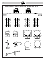
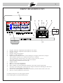
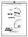
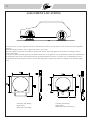
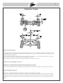
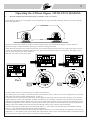
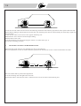
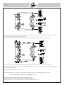
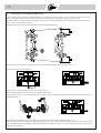
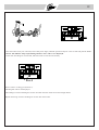
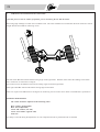
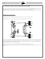
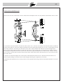
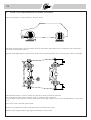
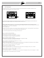
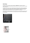
1
OPTO-PLUS 204
Type DSX2
OPTO-ELECTRONIC LASER ALIGNER
Operators manual
2
Operators manual for OPTO-PLUS wheel aligner
Model 204
Type DSX2
(Dual Sensor Doubble Laser)
INDEX
Accessories and specifications
Page 2 - 6
Alignment locations
7
Alignment angles
8-9
1.
Run-out compensation and rear Camber
10 - 12
2.
Front Toe, Set-Back and Front Camber
13 - 15
3.
Rear Toe
15 - 16
4.
Caster and King Pin
17 - 18
5.
Toe-out on turns
19
6.
Caster adjustment
20
7.
Front Camber adjustment
20
8.
Rear Toe adjustment
21
9.
Rear Camber adjustment
22
10.
Front Toe adjustment and Steering Wheel Centering
23 - 24
11.
Separate Front Wheel Alignment
25
12.
Program setup
26
3
OPTO-PLUS WHEEL ALIGNER MODEL 204 DSX2 is as standard supplied with the following accessories:
1.
2.
3.
4.
5.
6.
7.
8.
9.
10.
11.
12.
Measuring unit, left
Measuring unit, right
Retro-mirror for right rear wheel
Retro-mirror for left rear wheel
Self-centering wheel clamp for 12"-19" wheels. 4 pcs.
Steering wheel holder
Brake pedal depressor
Transformer 220V AC, 2x12 AC outlets.
Turntable with grading 60-0-60 degrees and nonius 10-0-10 degrees. 2 pcs.Maximum wheel load 1200 kgs.
Slide plate for rear wheels. Maximum wheel load 1200 kgs. 2 pcs.
Operators manual
Alignment data book
SCALE AND DISPLAY RANGE:
Run-out compensation
Individual Toe, front and rear
Total Toe, front and rear
Front wheel Set-Back
Camber, front and rear
Caster
King Pin
Turning Angle
: -6 to +6 degrees, resolution 1 minutes
: -2 to +2 degrees or +10 to -10mm.
: -4 to +4 degrees, or +20 to -20mm.
: 0 - 60 mm
: -6 to +6 degrees, resolution 1 minutes
: -18 to +18 degrees, resolution 1 minutes
: -18 to +18 degrees, resolution 1 minutes
: 0 to 60 degrees in and out,
resolution 10 minutes
All electronic measured values are permanently stored, also when the power is turned off.
From the factory the resolution on the displays are set to 1 minutes and the Caster/King Pin swing are set to 20°.
With the setup program described in section 12 the Caster/King Pin swing can be set to 10°, 14° or 20° and the resolution to 1
or 5 minutes. The values can be displayed in 1/60 or 1/100 of a degree.
The aligner is usable for vehicles with 12"-19" steel and alloy wheels.
Maximum outer tyre diameter is 870 mm.
MAINS SUPPLY
The measuring units operate on 12V AC/DC supply. The standard transformer can operate on an input voltage of 110/220V ±
10%, 50-60 cycles/sec. Other voltages on request. Power consumption 20VA.
The equipment should not be used in wet rooms.
4
OPTO-PLUS 4-WHEEL ALIGNER MODEL 204 DSX2
5
FRONT MEASURING UNIT
13
1
2
3
6
4
5
12
8
- +
11
10
9
7
1.
2.
3.
4.
5.
6.
7.
8.
9.
10.
11.
12.
13.
Program 1: Run-out compensation and Camber for rear wheels.
Program 2: Run-out compensation and Camber for front wheels.
Program 3: Caster.
Program 4: King Pin Inclination.
Program 5: Caster adjustment.
Digital display. Reading of Camber, Caster and King Pin in degrees and minutes of a degree.
The resolution is factory set to 1 minute, but can be set to 5 minutes.
The Caster/King Pin swing is factory set to 2x20°, but be set to 2x10° or 2x14°
The reading can also be set to 1/100 of a degree as resolution.
Negative readings indicated with a minus sign.
Program selector.
Button “1” for run-out compensation.
Button “2” for run-out compensation.
Button “ZERO” for Caster and King Pin measuring. Also used in Caster Adjust mode.
Toe-Scale. Laser beam points to scale with mm or degrees measurement. Readings are taken at the
horizontal line corresponding to the wheel size.
Scale for rear wheel alignment. Laser beam is reflected by the Retro Mirror back to this scale.
Knob for vertically adjustment of laser beam.
An Indicator lamp turns on for the program selected.
Caster and King Pin are measured simultaneously.
6
RETRO MIRROR FOR REAR WHEELS
The Retro Mirror has a twin scale system for measuring of individual rear Toe in one operation, independent of the Front Toe.
The twin scale system are used for compensating for the Front Toe value on the inner scale and thereafter taking the
reading of Rear Toe on the dial.
7
SELF CENTERING WHEEL CLAMPS
For 12-19 inch. steel and alloy wheels.
The jaws of the clamp can be turned for inside or outside clamping on the rim.
On steel wheels the jaws should normally grip at the inside of the rim, on alloy wheels an outside grip is recommended to
obtain secure clamping and to protect the rim against marks.
Inside clamping at the rim
Set the jaws for inside clamping and attach the clamp to the
rim. Adjust the jaws to fit the rim and slightly tighten the
handle of the clamp. Pull the clamp outward to make sure that
the jaws are gripping correctly. Now tighten the handle until
all four jaws are clamping at the rim. Make sure that the
clamping is reliable by shaking the clamp.
Outside clamping at the rim
Set the jaws for outside clamping and attach the clamp to the
rim. Adjust the jaws to fit the rim and slightly tighten the
handle of the clamp. Press the clamp inwards and tighten the
handle of the clamp until all four jaws are gripping behind the
rim lip. It may be necessary to perform this in more steps.
To facilitate clamping and for protection of the rims it
is recommended to lubricate the jaws of the clamp with
grease or tyre mounting fluid.
8
ALIGNMENT LOCATIONS
In order to ensure a correct alignment, all four wheels must be located on an area which is level in transverse and longitudinal
direction.
Admissible height tolerance: Left to right 2 mm, front to rear 4 mm.
The front wheels are placed on the turntables, and the rear wheels on the slide plates for easy transverse sliding to achieve
correct curb height.
In case the turntables and slide plates are not flush with the floor or the platform, it is recommended to place the turntables and
the slide plates after run-out compensation has been performed and then lower the car. further it is recommended to remove
the turntables and the slide plates before the vehicle after alignment is rolled away. Otherwise damage to the turntables might
occur.
Slide plate, full floating
Hight 29mm
Maximum load 1200kg
Turntable, full floating
Hight 49mm
Maximum wheel load 1200 kg
9
Alignment Angles
FRONT AND REAR TOE
The angles between straight forward position and inward position = positive and between straight forward and outward
= negative position of the wheel. The manufacturers specifications for Toe is normally the Total Toe, which is the sum
of left and right individual Toe.
Toe of each front wheel can be measured versus the geometric centerline or versus the thrust line of the rear wheels.
Toe of each rear wheel are measured versus the geometric centerline.
The geometric centerline is the line connecting the midpoints of front and rear axle.
THRUST LINE AND THRUST ANGLE
Thrust line is stated as the line bisecting the Toe angles of the rear wheels.
Thrust angle is the angle between the thrust line and the geometric centerline.
A vehicle with a solid rear axle will indicate a thrust angle if the rear axle is not square to the geometric centerline.
FRONT WHEEL SET-BACK
Set-back is a condition where one front wheel is rearward of the opposite front wheel.
Set-back is normally measured in mm versus a line square to the geometric centerline with the front wheels steered
straight ahead versus the geometric centerline. Set-back can also be measured in mm versus a line square to the thrust
line of the rear when the front wheels are steered straight ahead versus the thrust line, see centering of steering the
wheel.
10
Inclination of the wheel from vertical position in transverse
plane.
Inclination of the steering axis from vertical position in
transverse direction.
Inclination away from the vehicle: Positive
Inclination towards the vehicle : Positive
Inclination towards the vehicle : Negative
Inclination away from the vehicle: Negative
Inclination of the steering axis from vertical position in
lengthwise direction.
TOE-OUT ON TURNS
Inclination backwards: Positive
Inclination forwards : Negative
The difference between the turning angle of left and right front
wheel when driving in curves.Normally measured at 20 deg.
turning angle of the inner wheel.
11
Operating the 4-Wheel Aligner OPTO-PLUS 204-DSX2.
1.
Run-out compensation and measurement of Camber of the rear wheels.
If only the front wheels are to be aligned, run-out compensation is only performed at the front wheels, see section “Separate
front wheel alignment”.
Set the jaws of the wheel clamps for inside or outside clamping at the rims and attach the clamps to all four wheels as
described on page 6. Make sure that the clamping is reliable by shaking the clamps.
Attach left measuring unit to the clamp at the left rear wheel, and the right measuring unit to the clamp at the right rear wheel.
Connect the cable from the measuring units to the 12V outlets on the transformer and turn on the power. The displays shows
now the values from the last vehicle measured.
Raise the rear wheels to clear the ground.
Pos 1
Set the program selector on the front panel to Camber rear (Position 1).
The values shown at the display will be automatically erased from the memory when a new run-out compensation is performed.
(The values can also be erased by pushing button “1” and “2”).
Loosen the cam lock and rotate the wheel slowly while keeping the measuring unit fairly horizontal. Stop the wheel when the
display reading is exactly at the maximum. To make sure that the exact maximum is obtained, rotate the wheel to left until the
reading has decreased 2 minutes and note the position of the wheel. Then rotate the wheel to right until the reading has passed
maximum and again decreased 2 minutes. Note the position of the wheel. Rotate the wheel back to the position for maximum
reading, which is the middle position between the left and right position with 2 minutes decreased reading.
Level the measuring unit, tighten the cam lock and push button “1”. The Camber rear indicator lamp starts flashing. Pushing
button “1” again cancels the operation and the lamp stops flashing.
Loosen the cam lock and rotate the wheel exactly 180° (Half a revolution). Level the measuring unit, tighten the cam lock and
push button “2”. The indicator lamp stops flashing. The compensation values are now stored in the memory. The wheel must not
be rotated away from this position when it is lowered onto the slide plates.
12
If by a mistake button “1” is pushed again, the indicator lamp starts flashing. Push button “1” once more to stop the indicator
lamp from flashing.
Repeat the run-out compensation for the other rear wheel. Be sure that the first rear wheel stays in compensated position
while compensating the other rear wheel. If neccessarely use a rubber pad between the ground and tire.
Apply the brake pedal depressor to activate the brakes thereby locking the wheels.
Lower the rear wheels slowly onto the slideplates while keeping the rear wheels in compensated position. Bump the car to
assure proper vehicle curb height.
Loosen the cam lock and level the measuring units. Tighten the cam lock again.
Read Camber of the rear wheels on the displays in degrees and minutes of a degree.
After having removed the measuring units from the clamps at the rear wheels for continuing the measurement procedure, the
rear Camber values can be recalled any time mounting the measuring units to the clamps at the rear wheels and setting the
program selector in position 1.
Move the measuring units from the clamps at the rear wheels to the clamps at the front wheels.
If convenient, the measuring units can be temporarily disconnected from the transformer without erasing the values stored in
the memory. Raise the front wheels clear of the ground.
Pos 2
Set the program selector to Camber front (Position 2).
Loosen the cam lock and rotate the wheel slowly while keeping the measuring unit fairly horizontal. Stop the wheel when the
display reading is exactly at the maximum.
Level the measuring unit, tighten the cam lock and push button “1”. The Camber front indicator lamp starts flashing.
Loosen the cam lock and rotate the wheel exactly 180° (Half a revolution). Level the measuring unit, tighten the cam lock and
push button “2”. The indicator lamp stops flashing. The compensation values are now stored in the memory. The wheel must not
be rotated away from this position when it is lowered onto the turntables.
13
Repeat the run-out compensation for the other front wheel. Be sure that the first front wheel stays in compensated position
while compensating the other rear wheel.
Apply the brake pedal depressor to activate the brakes thereby locking the wheels.
Lower the front wheels slowly onto the turntables while keeping the front wheels in compensated position. Bump the car to
assure proper vehicle curb height.
All wheels are now compensated for run-out in the wheels and in the clamps, and the alignment of the car can be measured.
Mount the Retro Mirrors to the clamps at the rear wheels, with the mirrors facing the front measuring units.
In order to ensure a correct wheel alignment, check the vehicle for:
Same size and type of wheels and tyres
Condition of king pins, wheel bearings and track rod joints
Condition of springs and suspension
Air pressure in tyres
Loading of car during alignment according to manufacture specifications
14
2.
MEASURING OF FRONT TOE, SET-BACK AND CAMBER.
Focus the rear laser beam on the scale on the Retro-Mirrors at the rear wheels. Steer the front wheels until left and right
reading on the scales are the same. The front wheels now are steered straight ahead and they have equal toe with respect to the
geometric centre line of the front and rear wheels.
Run-out compensation on the front wheels should be performed as described in section 1 before measurements are taken.
Set the measuring units in level and tighten the cam lock. Turn the front laser beam until the beam hit the Toe-scales on the
opposite measuring unit.In cases where the front end of the vehicle is so low, that the beams are interrupted the front head can
be lowered as explained on next
15
Set-Back is a condition where one front wheel is rearward of the opposite front wheel, which means that the front axle is not
square to the geometric center line.
The projection screens have at the top a scale for measuring Set-Back i mm. The vertical “0” line of the Toe-scale is used as a
pointer to the Set-Back scale. The Set-Back value is the difference in the readings on left and right Set-Back scale. The wheel
has “Set-Back”in relation to the other wheel, on the side with the highest reading.
Read Camber of left and right front wheel at the displays. The readings are as standard in degrees and minutes of a degree.
X3
X1
Pos 5
Pos 3
Vehicles with low front spoiler
In cases where the front end of the vehicle is so low, that the projected Toe-scales are interrupted, the front end of the
measuring units should be tilted down to let the Toe-scales pass under the body as described below.
Set both units for measuring of Caster = program selector on pos. 3.
Level the measuring units and push the ZERO-button 3 times to set the displays on zero reading.
Set the program selector on both units to “Caster adjust” = selector on position 5, and push the ZERO button to recall the value
0.00.
16
Loosen the cam lock and tilt the front end of the measuring unit downwards until the projected Toe-scales passes under the body
and the display reading on left and right unit are the same. The measuring units have now been tilted by the same angle. Tighten the
cam locks again.
Focus the Toe-scales on the screen of the opposite measuring unit.
Read total front Toe as the sum of left and right reading.
Read Set-Back on the scales.
Level the measuring units and set the program selector on Camber front (pos. 2).
Proceed the measuring procedure.
3.
MEASURING OF LEFT AND RIGHT REAR TOE.
After measuring of the front Toe, the individual rear Toe can be measured.
Run-out compensation on the rear wheels should be performed as described in section 1 before measurements are taken.
The front wheels shall be positioned straight ahead .
Level the measuring units and tighten the cam locks.
Tilt the Retro-Mirror until the laser beam is reflected to the scale at the back of the measuring unit.
17
17
Turn the scale knob at the rear of the Retro-Mirror until the inner “Silver” scale is set to half the measured front Toe value.
Use the line on the transparent window as a pointer.
Then while holding the scale knob fixed in this position, turn the outer Dial with the red scale to the value 0°.
Turn the scale knob until laser beam is focused at the 0-line of the scale on the back of the front measuring unit.
The Toe value of the rear wheel can now be read on the Red Scale on the outer dial. The reading is in degrees and minutes of a
degree, graduation 5 minutes.
Repeat the measuring for the other rear wheel.
Thrust line angle of the rear wheels is calculated as half the difference between left and right rear Toe value.
Thrust Line Angle = (Left Rear Toe - Right Rear Toe) / 2
When both readings are positive: Subtract the readings and divide by 2.
When both readings are negative: Subtract the readings and divide by 2.
When one reading is positive and one is negative: Add the readings and divide by 2.
18
4.
MEASURING OF CASTER AND KING PIN
Caster and King Pin are measured simultaneously by a preset Caster swing of 2x10°, 2x14° or 2x20° in and out. The Caster
swing is selected with the Setup program as described on the last pages. The value is factory preset to 2x20°.
The ZERO-button is used for erasing the values from the previous measurement of Caster and King Pin, and subsequently to
store in memory the measured values.
The brake of the front wheels must be firmly blocked during the measuring.
Steer the front wheels until the readings on the scale at left and right Retro-mirror are the same, A = A.
Zero-set the scales on the turntables.
Pos 3
Set the selector on left measuring unit to Caster (Position 3).
Push the ZERO-button to erase the old Caster and King Pin values.
The display now shows +20, corresponding to a 20° Caster swing inward of the wheel. (Presumed that the Caster swing is not
changed from 20°).
If by a mistake the ZERO-button is pushed twice, push the button again until the display shows +20.
Steer left wheel exactly 20° inward (or the displayed angle for Caster swing). Hold this position steady for a few seconds and
push the ZERO button. The indicator lamp starts flashing and the display shows -20 (or the actual preset angle), referring to an
outward turn of the wheel.
19
Steer the wheel exactly 20° outward (or the actual preset angle). Hold the position steady for a few seconds and push the ZERO
button. The indicator lamp stops flashing and the Caster value is now displayed.
In the same time King Pin is measured, and both values are stored in the memory.
Pos 4
Set the selector to King pin (Position 4).
The King Pin value is now displayed.
The readings of Caster and King Pin can also be taken when the wheels are steered straight ahead.
Repeat measuring of Caster and King Pin for the other front wheel.
20
5.
TURNING ANGLE AND TOE-OUT ON TURNS
*Note that front toe must be within specification prior to measuring the Toe Out On Turns.
The turning angle readings are taken on the turntable scales. The scales should be zero-setted when the front wheels are steered
straight ahead as described for measuring of Toe.
Steer left wheel 20° outward and read the turning angle of the right wheel. With the nonius scales the readings can be taken
with a resolution of 10 minutes of a degree.
Toe Out On Turns is the difference between the turning angles of left and right wheel.
Steer right wheel 20° outward and read the turning angle of left wheel.
Some cars require turns different from 20 degrees for measuring of Toe Out On Turns. Refer to manufacturers specification.
NOTES ON ADJUSTMENT
The vehicle should be adjusted in the following order:
Rear Camber (if adjustable)
Rear Toe (if adjustable)
Caster and Camber (one side)
Caster and Camber (opposite side)
Front Toe
If a clamp is removed during the adjustment, run-out compensation must be performed when re-installed.
21
6.
CASTER ADJUSTMENT
Steer the front wheels straight ahead .
Pos 5
Level the measuring units and tighten the cam lock.
Set the selector to Caster adjust (Position 5).
Push the ZERO button.
The measured Caster value is now displayed. Any change in level position of the measuring unit caused by adjusting the Caster
angle will increase or decrease the reading on the display, giving the new adjusted value of Caster.
Adjust Caster until the displayed value is inside the desired Caster range specified by the car manufacturer. The wheel should be
straight ahead when the reading is taken.
Be aware that the original measured Caster value is allays recalled when pushing the ZERO button, as the machine only
remember the original measured value. To load the new Caster value in the memory, measuring of Caster must be repeated.
Check that the Camber and Toe values still are inside the desired range.
7.
FRONT CAMBER ADJUSTMENT
Set the program selector to Camber front (position 2).
Steer the front wheels straight ahead.
Adjust Camber until the display shows the desired Camber value. When the reading is taken, the wheel should be straight ahead.
22
8.
ADJUSTMENT OF REAR WHEEL TOE
Measure rear wheel Toe as described in section 3.
The front wheels are then in straight ahead position, the laser beams pointing to the 0-line on the scale at the rear of the
measuring units. Left and right rear wheel Toe can be read on the outer red scale of the Retro-Mirrors.
Turn the scale knob on the Retro-Mirrors, until the outer red scale is set to the desired Toe value for each rear wheel. This
value will normally be set to half the desired Total Toe for the rear wheels, thus giving a zero value for the Thrust angle of the
rear wheels.
The sight crosses are are thereby moved away from the 0-line of the scale at the rear of the measuring units.
Now adjust Toe of the rear wheels until the Sight crosses again is focused on the 0-line of the scale at the rear of the measuring
units.
After this procedure have been performed for both rear wheels, the individual rear Toe have been adjusted to the desired value,
and the Thrust angle will be zero.
23
9.
ADJUSTMENT OF REAR WHEEL CAMBER
Remove the Retro-Mirrors from the clamps at the rear wheels.
Remove the measuring units from the clamps at the front wheels, and attach them to the clamps at the rear wheels.
If convenient, the power supply can be disconnected while moving the measuring units without loss of measured data.
Pos 1
Set program selector to Camber rear (position 1).
Camber of the rear wheels are now displayed.
Adjust Camber until the display shows the desired value.
On some type of rear suspensions, adjustment of camber also influence the Toe value. In this case it is recommended to check
the Toe value, and if necessary adjust Toe again.
24
10.
ADJUSTMENT OF FRONT TOE AND CENTERING OF STEERING WHEEL
When adjusting Toe of the front wheels it is important to do this with respect to the Center Point Steering, meaning that the
steering gear and the steering wheel are in center position when the vehicle is steering straight ahead.
The thrust line of the rear wheels is used as reference for aligning the front wheels, as this ensures the ideal 4-wheel alignment.
Vehicles with only one adjustable tie rod.
Measure the front Toe as described and measure and adjust the rear Toe (If possible) as described.
Adjust front Toe until the sum of left and right reading is equal to the desired Total Toe value.
Turn the knob of the Retro Mirror until the inner Silver Scale is at 0°. Steer the front wheels uftil the laser beams are reflected
from the Retro-Mirrors to the same reading at the Back scale of left and right measuring unit. In case it is impossible to get
the beams within the scale limits, the inner Silver Scale value is offset with the same amount on the left and right Retro Mirror,
until left and right sight cross are within the scale limit.
The front wheels are now steered to straight ahead position versus the thrust line of the rear wheels.
The steering wheel should now be in center position. If not, dismantle the steering wheel from the shaft and mount it in correct
position.
25
Vehicles with two adjustable tie rods.
Measure the front Toe as described in section 2 and measure and adjust the rear Toe (If possible) as described in section 3 and
8.
Turn the knob of the Retro Mirror until the inner Silver Scale is at 0°. Steer the front wheels until the laser beams are reflected
from the Retro-Mirrors to the same reading at the Back scale of left and right measuring unit. In case it is impossible to get the
laser beams within the scale limits, the inner Silver Scale value is offset with the same amount on the left and right Retro
Mirror, until left and right laser beams are within the scale limit. Set the steering gear in center position according to mark or
by turning the steering wheel from the extreme left to the extreme right, and then half the revolutions back. Lock the steering
gear, or lock the steering wheel with the steering wheel holder. Check that the idler and steering arm are in line with the center
line of the vehicle.
Loosen the tie-rod ends and adjust Toe of each wheel to half the desired Total front Toe. Check that the laser beams are reflected to equal readings on the back scales of left and right measuring unit. Tighten the tie-rod ends.
The Steering wheel should now be in center position. If not, dismantle the steering wheel from the shaft and mount it in correct
position.
26
11.
INSTRUCTION FOR SEPARATE FRONT WHEEL ALIGNMENT
Run-out compensation is only performed at the front wheels.
Attach the measuring units to the front wheels. Raise the front wheels and perform run-out compensation for left and right
front wheel as described in section 1.
Apply the brake pedal depressor and lower the wheels onto the turntables. Bump the car to assure proper vehicle curb height.
Attach the Retro-Mirrors to the rear wheels with the mirrors facing towards the front end.
(For OPTO-PLUS model 202 the indicator scales are attached to the rear wheels).
Focus the Sight Crosses and steer the front wheels until left and right reading on the scales at the Retro-Mirrors are the same,
A = A.
Zero-set the scales of left and right turntable.
Measure Toe, Set-Back and camber of the front wheels as described in section 2.
Measure Caster, King Pin and Turning Angle as described in section 4 and 5.
27
12.
The Setup program
The SETUP program is used for selecting the parameters for the measurements, for automatic calibration of the
transducers and to diagnostics of the electronic system.
Enter the setup program, hold down the Zero-button and turn on the power. While holding down the Zero-button the
display starts counting through all steps starting with 00.00 in steps of 11.11.
When the ZERO-button is released, “L” for left is shown on the left measuring unit and “H” for right on the right
measuring unit. If the readings are faulty, positive and negative readings are shown inverted. The readings can be corrected
by pushing button “1” for run-out compensation.
Push the ZERO-button
Selection of one of the 5 modes can now be done with the program selector switch. The mode number corresponds with
the measuring program number. The corresponding indicator lamp flashes fast.
To exit the setup program and save the settings turn off the power.
Mode 1, manual transducer adjustment.
Program selector on program 1, Camber rear.
The uncompensated value from the transducer is displayed.
Used for diagnostic of faults in transducer and electronics.
Mode 2, automatic transducer calibration.
Program selector on program 2, Camber front. Take care not to change the reading.
The calibration should only be performed by service staff.
Mode 3, Selection of Caster/King Pin swing of 10°, 14° or 20°.
Program selector on program 3, Caster.
With the compensation buttons 1 or 2 switch between the values shown on the display for measuring of Caster and King
Pin by 10°, 14° or 20° turn in and out of the wheel. Factory set to 20°.
Mode 4, selection of display resolution of 1 or 5 minutes.
Program selector on program 4, King Pin.
With the compensation buttons 1 or 2 switch between the values shown on the display. Factory set to 1 minute.
Mode 5, selection of 1/60 or 1/100 of a degree as resolution.
Program selector on program 5, caster adjust.
With compensation buttons 1 or 2 switch between the values shown on the display. Factory set to 1/60 degree = 1 minute.
The SETUP values are stored when the power is turned off.