1
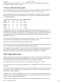
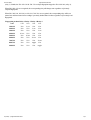
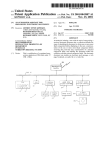
03-12-2010
requirements.html
User guide – Fingerprint Relay Box
User guide - Fingerprint Relay Box
Introduction
Electrical connections
Communication parameters
Mode selection
Fingerprint reader association (learning mode)
Startup messages & Log output
Boot message
Messages during normal operation
Limitations
Other devices
N-factor authentication mode
MAP Fingerprint mode
Introduction
The Fingerprint relay box enables you to control up to 4 relays using 4 or more distinct fingerprints.
The Fingerprint Relay Box comes preconfigured, and there’s no need for further configuration by PC or other
configuration software.
The Fingerprint Relay Box has 2 jumper selectable modes of operation; “n-factor authentication” and “Map
Fingerprint authentication”.
Electrical connections
The Fingerprint relay box needs only 12VDC and communication/data connections.
The power supply must be connected to terminals 12V and 0V. Ensure, that the polarity is correct before
powering on the device.
Communication is established by connection the blue wire from the Fingerprint reader to terminal “B”. The
Orange wire must be connected to terminal “A”.
The maximum power consumption is 100mA (when all relays are set).
Communication parameters
The Fingerprint reader must be configured with the correct communication parameters. Normally this has
already been done during production. However, if you expirince communication problems make sure, that the
Fingerprint reader communication parameters are set up for:
9600 BAUD
8 databits
No Parity
1 stop bit
Mode selection
The mode of operation is defined during power-on. Simply attach or remove the Jumper jp1 from the
Fingerprint Relay Box to select mode.
D:/C59/…/requirements.html
1/5
03-12-2010
Mode
n-factor authentication
requirements.html
Jumper removed(default) Jumper attached
X
Map fingerprint authentication
X
If the Jumper is not present, only n-factor authentication is possible.
The jumper should remain seated or detached while powered on, since changing the setup during operation
may cause undesireable sideeffects.
If you wish to change the operation mode, power off the device and change the jumpersetting. When the unit
is powered back up, the operational mode is changed.
Fingerprint reader association (learning mode)
You may decide to connect multiple Fingerprint readers to the same communication bus (RS485). In this
case, each fingerprint reader should have an unique module ID in order to communicate unambigiously.
If you need to accociate a Fingerprint Relay Box with one or more Fingerprint readers, you may do so by
setting the Fingerprint Relay box in learning mode.
Learningmode is set by attaching jumper 2 pin 1 + 2 before powering on the Fingerprint relay box. When
powering on in learning mode, previously learned module ID’s are erased.
D:/C59/…/requirements.html
2/5
03-12-2010
requirements.html
It is currently possible to associate up to 128 module ID’s (Fingerprint readers) with a single Fingerprint
Relay box. Please note, that this number is likely to be reduced to 32 modules in future versions.
When all module ID’s has been added/learned, you should remove power and then remove jumper 2 before
applying power.
Startup messages & Log output
Under certain circumstances human readable strings (US-ASCII) are sent to the data bus. These strings are
readable using a standard serial-terminal application such as hypercom, putty or realterm. For windows we
recommend using putty (http://http://www.putty.org/) and for other operating systems putty or minicom
(http://freshmeat.net/projects/minicom/).
Boot message
When booting, the Fingerprint Relay Box will print out (send data to the communication bus) versioninfo.
FPRELAY 1.6
[MODE] mode ([STATE])
where [MODE] is either “Unique FP” or “Map FP” depending on jumper 1 setting and [STATE] is either
“work” or “learn” depending on jumper 2 setting.
Messages during normal operation
Each time a valid fingerprint is processed, the corresponding fingerprint ID is sent to the bus. The format is
"Userid: number"
where number is a 6-digit integer. In case the number requires fewer digits, the number is prepended with 0’s
(zeros) until the number string is 6 digits wide.
Limitations
Other devices
The Fingerprint Relay Box has been tested in conjunction with fingerprint readers and fingerprint reader
D:/C59/…/requirements.html
3/5
03-12-2010
requirements.html
configuration software. If you decide to connect other devices to the same communication bus, please be
aware, that undesired sideeffects may arrise.
N-factor authentication mode
N-factor authentication (or Multi-factor authentication) means using any independent two-four fingerprints to
increase the assurance that the bearer has been authorized to access secure areas or systems.
The factors (fingerprints) may be associated with several individual beareres. That is, using the Fingerprint
Relay Box you may define a system, which only allows access if more 2-4 individual persons grants access
by swiping their fingerprint.
State Relay 1 Relay 2 Relay 3 Relay 4 Authentication
off
off
off
off N/A
IDLE
off
off
off 1-factor
State1 on
State2
State3
on
on
on
on
off
on
off
off
2-factor
3-factor
State4
on
on
on
on
4-factor
An authentication session starts by swiping the first fingerprint. If the fingerprint is known/approved to the
Fingerprint reader, a message is sent through the standard RS485 serial bus. The Fingerprint Relay Box will
recieve the message, and then open the first relay. If a second fingerprint (unique for this session) is approved,
the second relay will be switch on. Similarily the thrid and fourth relay will be switched on when unique
fingerprints are approved.
A timeout counter ensures that any active relay is reset after a timeout (t1~120sec). However, this timeout is
reset each time a unique fingerprint is swiped (maximum 4 resets during a session).
The N-factor can defined simply by choosing the appropriate relay.
Please note, that in situations where multiple fingerprint readers are associated with a single Fingerprint Relay
Box, each fingerprint reader should have the same mapping of fingerprint ID’s.
For example if a persons’s fingerprint is stored at position 20 on the first fingerprint reader and position 34 in
the second fingerprint reader, this person will be able to perform successfull 2 factor authentication. If the
fingerprints are stored at the same position the Fingerprint Relay Box will ignore the second input.
MAP Fingerprint mode
This mode allows you to asociate one or more fingerprints to a single relay. The association is done simply by
defining the fingerprint ID when enrolling new fingerprints. In order to associate a fingerprint with a specific
ID, the enrollment process must be controlled by a PC program. (UniFinger or similar).
ID’s between 0 and 399 are associated to relays 1-4, each swipe sets the relay for 5 seconds
ID’s between 400 and 799 are also associated with relays 1-4. The difference is, that the relay will be set for
30 seconds
The term “sets” means, that the relay is powered on until a timeout. The timeout is reset (timer starts over) if a
second finger is approved regardless of the current timeout status. That is, the set-period may be prolonged
by quickly re-swiping the fingerprint.
Finally ID’s 800-999 are used for toggling relays 3 and 4. That is, approved fingerprints stored with id 800899 togles relay 3 each time a fingerprint is swiped. If relay was previously on, the relay will be turned off. If
the relay is turned off, toggling will set the relay on.
The relay mapped to fingerprint ID’s 200-299 & 600-699 overlaps fingerprints mapped to ID’s 800-899
D:/C59/…/requirements.html
4/5
03-12-2010
requirements.html
(relay 3). Similar, the ID’s 300-399 & 700-799 overlaps fingerprints mapped to ID’s 900-999 (relay 4);
When ID’s 800..999 are recognized, the corresponding relay will change state regardless of priviously
swipedd fingerprints.
When ID’s 200-299, 600-699 or 300-399, 700-799 are recognized, the corresponding relay will be set
(turned on) and later turned off according to previously defined timeout values regardless of previously read
fingerprints.
Fingerprint position Relay 1 Relay 2 Relay 3 Relay 4
5 sec
N/A
N/A
N/A
0-99
N/A
5 sec
N/A
N/A
100-199
200-299
N/A
N/A
5 sec
N/A
300-399
400-499
N/A
30 sec
N/A
N/A
N/A
N/A
5 sec
N/A
500-599
N/A
30 sec
N/A
N/A
600-699
700-799
N/A
N/A
N/A
N/A
30 sec N/A
N/A 30 sec
800-799
N/A
N/A
toggle
N/A
900-999
N/A
N/A
N/A
toggle
D:/C59/…/requirements.html
5/5