1
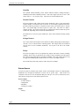
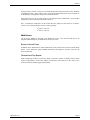
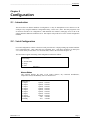
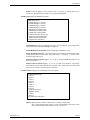
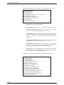
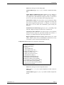
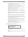
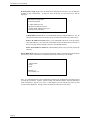
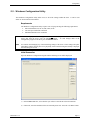
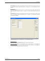
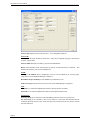
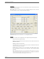
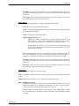
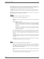
e-mail: [email protected]
tel: 08-52 400 700 fax: 08-520 18121
User’s Manual
Installation and Operation Guidelines
SNMP-Link SL10 Remote Site Manager
© 2006 Omnitronix, Incorporated. All rights reserved.
The content of this manual is furnished for informational use only, and is subject to change without notice.
Examples, data, and names used in this manual are examples and fictitious unless otherwise noted. No part of this
document may be reproduced or transmitted by any means, electronic or mechanical, without the express written
permission from Omnitronix, Incorporated.
Omnitronix and SL10 are trademarks of Omnitronix, Incorporated.
Rev. 3.10
PN: 3020-036 Cover: 2057-036
Printed in the United States of America
Table of Contents
CHAPTER 1 ..................................................................................................................................................1
Overview ...................................................................................................................................................................... 1
1.1 - Introduction ...................................................................................................................................................... 1
1.2 - Quick Start ........................................................................................................................................................ 2
1.3 - Communication Features .................................................................................................................................. 2
Password Protection .......................................................................................................................................... 3
Remote IP Assignment ...................................................................................................................................... 3
Terminal Server / Serial Passthrough ................................................................................................................ 3
FTP Upgrades.................................................................................................................................................... 3
1.4 - Environmental Controls and Alarms ................................................................................................................ 3
On-Board Sensors.............................................................................................................................................. 3
External Sensors ................................................................................................................................................ 4
SNMP Alarms ................................................................................................................................................... 5
CHAPTER 2 ..................................................................................................................................................7
Configuration .............................................................................................................................................................. 7
2.1 - Introduction ...................................................................................................................................................... 7
2.2 - Serial Configuration.......................................................................................................................................... 7
Alarms Status..................................................................................................................................................... 7
Setup .................................................................................................................................................................. 8
2.3 - Windows Configuration Utility ...................................................................................................................... 17
Requirements................................................................................................................................................... 17
Initial Connection ............................................................................................................................................ 17
Tabs ................................................................................................................................................................. 18
CHAPTER 3 ................................................................................................................................................27
Warranty ................................................................................................................................................................... 27
Manual Rev.3.10
_________________________________________________________________________________________________Overview
Chapter 1
Overview
1.1 - Introduction
The SL10 is a rack-mountable site monitoring and communications device capable of measuring
temperature, humidity, voltage levels, and contact closures. It has the ability of functioning as a terminal
server and can deliver notifications of alarm situations via SNMP.
With a slim 1U profile and several convenience features including detachable screw terminals, the SL10
provides an excellent solution for site monitoring and equipment management. Using non-volatile flash
memory, the SL10 has the ability to preserve its custom configuration through any length of power failure.
There is no need for battery replacement or worry about data loss in the event of a power failure.
Figure 1: SL10 Front
The SL10 is built to either mount on a wall or in a standard 19” equipment rack, consuming only 1U of
space. The image above shows the front side of the SL10. Buttons and LEDs from left to right are: Reset
button, Clear button, Active Modem LED (future use), Alarm LED, Ethernet Link and TX (transmit)
LEDs, and Power LED.
The Reset button causes the SL10 to restart and resume running with the same configuration. The Clear
button is used in combination with the Reset button to reset all alarms to an inactive state and restores
factory default settings. To do this, press both the Clear and Reset buttons simultaneously. Release the
Reset button and hold the Clear button in for another two seconds. After releasing the Clear button, the
unit will reset to factory default settings and reboot.
Figure 2: SL10 Back
The image above shows the backside of the SL10. The connectors shown from left to right are: Power
input (12VAC or –48VDC), voltage outputs (not used), Semsor Input (contact closure) and Relay
terminals, Omnitronix Event Sensor bus, DB9F serial port, RJ45 Ethernet port (10BaseT), and RJ11
internal modem port (future use).
Manual Rev. 3.10
Page 1
Omnitronix SL10 User’s Manual
1.2 - Quick Start
The SL10 can be used to monitor sensors in a relatively short amount of time. This section will cover the
process to get the unit up and sensing contact closure events. This tutorial assumes that you are connecting
via network, have the following available: a contact closure compatible sensor, Windows PC, an SNMP
manager, power, and TCP/IP network connections.
Unpack and connect the power and Ethernet cables to the SL10. At this time, you should also connect your
sensor to the SL10 contact closure terminals one and ground. Note the unit’s MAC address, as it will be
needed to assign an IP.
Return to your networked PC and enter the following commands:
ARP –s nnn.nnn.nnn.nnn xx-xx-xx-xx-xx-xx
PING nnn.nnn.nnn.nnn
Insert the desired IP address in the place of nnn.nnn.nnn.nnn, and insert the MAC address listed on the
SL10 unit label in place of xx-xx-xx-xx-xx-xx.
Once an IP address is assigned to the SL10, insert the disc containing the Windows Configuration Utility
software and install the application. After installing, run the program and set the Connection Via option to
Network/IP. Next, enter the IP address into the proper field, the default password password into the
Password field, and press Get Data to retrieve the current settings and status from the SL10.
On the Contacts tab, enter an appropriate name for Contact 1. The Current State field indicates the status
of the sensor at the time you pressed Get Data. Select Alarm Enabled and then choose an appropriate
Active When state.
In the SNMP field of the Security tab, input the IP address of the computer running the SNMP trapreceiving program. Press Set Data to store the settings and then press Send Test Trap to test out the
SNMP manager. The SNMP manager or trap-receiving program should receive an SNMP trap very
shortly.
Once the CC and SNMP manager are configured, you are free to toggle the contact closure sensor and test
the SNMP reporting. You will receive an SNMP trap for each time the sensor goes active unless you have
Send Return to Normal Trap turned on, in which case traps will be sent when the alarm goes active and
then returns to inactive.
1.3 - Communication Features
The SL10 allows administrative connections via the serial port or Ethernet. Configuration of the device is
handled via SNMP, serial port configuration or Windows Configuration Utility. The MIB used with SNMP
is supplied on a CD ROM along with the SL10.
Please refer to Serial Configuration and Windows Configuration Utility – Tabs sections in the following
chapter for instructions on how to configure the following communication features.
Page 2
Overview
Password Protection
The SL10 has the ability to secure connections to itself and the devices connected to it. The
following communication methods may be password protected:
•
•
•
•
Ethernet Administrative access – encrypted password
SNMP (via community names)
FTP access
Passthrough (terminal server)
Since connecting any device to a network or the Internet often presents a whole host of security
concerns, the SL10 has the ability to limit the IP addresses allowed to manage the device and
change its settings. Up to eight individual IP addresses may be defined, or none at all if you wish
to allow all incoming network connections. If blocked, a computer attempting to access the
SL10’s configuration system will be summarily ignored.
Remote IP Assignment
Using the MAC address of the SL10, it is possible to assign an IP address to the unit if it has none
assigned (as detailed in section 1.2 Quick Start). Using a computer on the same network, perform
an ARP command and then PING the SL10. It will take the same IP address used in the ARP.
Using this method, a direct serial connection is not necessary to configure the IP. An example
ARP command might look like this:
arp -s 1.2.3.4 00-01-a3-01-28-99
ping 1.2.3.4
In the above commands, you would replace 1.2.3.4 with your desired IP address and replace the
example MAC address with the one printed on the SL10 label. After running the above
commands, the box would take on the given IP and assume a subnet mask of 255.255.255.0.
Terminal Server / Serial Passthrough
The SL10 allows for password-protected access to devices connected to its serial port. This
functionality allows the SL10 to act as a terminal server for any serially connected device. Telnet
to port 2101 (default) will connect the user directly to the serial port.
FTP Upgrades
The SL10 may be remotely upgraded to the latest Omnitronix firmware via FTP while preserving
the current configuration. To perform this action, please refer to the instructions provided with the
upgrade files from Omnitronix Technical Support.
1.4 - Environmental Controls and Alarms
On-Board Sensors
Temperature
The temperature sensor is located on the right back panel of the unit on a tab that sticks
out. This sensor reads from 0 to 130 degrees Fahrenheit with an accuracy of +/- 1.8
degrees F.
Manual Rev. 3.10
Page 3
Omnitronix SL10 User’s Manual
Humidity
The optional internal humidity sensor outputs ambient moisture readings through a
standard percent relative humidity measure. This value ranges from 20% to 90%. This
sensor offers a +/- 3% accuracy range. This sensor is located within the unit.
Contact Closures
The SL10 supports eight contact closure inputs (numbered 1 thru 8 on the back panel).
Contact closures (CC) sense the state of a circuit. A weak voltage is applied to the source
pin and if pulled to ground by a connection on the circuit, the sensor reports a "closed"
state. If it remains high, the sensor reports an "open" state. All of the CCs share a
common ground. The contact closures may be configured to alarm in either the open or
closed state, depending on the needs of the attached devices.
The leftmost set of two screw pairs (numbered 1 and 2) can be defined as analog voltage
sensors.
Voltage Sensors
Two of the contact closure inputs can be ordered as analog voltage inputs measuring 0-5
volts DC, or 0-75 volts DC with a common ground. The voltage sensors are interfaced
via two pairs of screw terminals (numbered 1 and 2) just to the left of the contact
closures.
Relays
The SL10 can support one or two optional relay outputs with 30W (1A max) switching
capability. These relays are interfaced via two pairs of screw terminals just to the right of
the contact closure inputs and are controlled via SNMP. These relay outputs may be used
to trigger non-SNMP capable systems such as AC or heat, or perhaps an alarm.
The current status of the relays may be read at any time via SNMP.
External Sensors
To meet the needs of customers who require various environmental sensors in a small package,
Omnitronix has developed EventSensors (version 2.00 or greater only). These devices are
connected to the SL10 via the EventSensor Bus port and up to two can be connected in series.
These devices can provide several different means of I/O:
Sensors (Input)
• Contact closures
• Temperature
• Humidity
• Voltage (0-75VDC)
Output
• Relays
Page 4
Overview
Settings for these sensors or relays are accessible through the serial port interface or the Windows
Configuration Utility. Sensor values can be viewed on the Alarm Status menu on the serial port or
on the Windows Configuration Utility tab for External Sensors.
These add-on devices can be ordered with several different sensor combinations. Please contact
Omnitronix for more information about these devices.
Note: EventSensors connected to an SL10 must have the jumpers on the sensor set as follows,
(where X is a connected jumper, and 0 is a removed jumper:
1st sensor: X X X X
2nd sensor: 0 X X X
SNMP Alarms
The SL10 uses SNMP for reporting of all alarms and events. The unit will send traps to its
assigned SNMP manager(s) as notification of all sensor events.
Return to Normal Traps
In addition to the standard active alarm notifications, the SL10 also offers return-to-normal (RTN)
alarms. These alarms are optional SNMP notifications that signal an “all clear” status for the
devices monitored.
Threshold and Trap Repeat
When configuring an alarm, you have the ability to select the number of minutes between alarm
repeats (Trap Repeat) as well as the number of seconds the sensor must be in the “active” state
before the alarm is actually triggered (Threshold).
Manual Rev. 3.10
Page 5
______________________________________________________________________________________________Configuration
Chapter 2
Configuration
2.1 - Introduction
The SL10 offers two distinct methods of configuration. It may be manipulated via text menus over the
serial port or by using the Windows Configuration Utility, version 5.00. (Note: The same program is used
for the SL10 and SL12 for configuration.) Both methods offer intuitive, multi-page access to all of the
settings and status indicators within the SL10. This chapter will provide an overview of both configuration
methods.
2.2 - Serial Configuration
For serial configuration, connect to the SL10 serial port with a PC or laptop running any terminal emulator
set to 19200 baud, 8N1. Once connected, press <ENTER> twice. Note that in all menus you must press
“X” to return to the previous menu. To exit serial mode, return to the root menu and press “X”.
The first menu to appear when using serial configuration will look as follows:
SL10 Setup
1. Alarms Status
2. Setup
X. Exit
Selection ?
Alarms Status
This selection displays the status of all contact closures, any connected EventSensors,
Temperature sensor, and Humidity sensor as shown below.
Selection ? 1
1: Input 1
2: Input 2
3: Input 3
4: Input 4
5: Input 5
6: Input 6
7: Input 7
8: Input 8
Temperature:
Humidity :
Manual Rev. 3.10
Opened
Opened
Opened
Opened
Opened
Opened
Opened
Opened
68F
34%
= Normal
= Normal
= Normal
= Normal
= Normal
= Normal
= Normal
= Normal
= Normal
= Normal
Page 7
Omnitronix SL10 User’s Manual
Setup
This selection displays the SL10 Setup Menu as shown below. The top line of this menu includes
the MAC address, serial number, and firmware version of this SL10.
SL10 Setup Menu 00:10:A3:30:35:0D 1030350D STD 3.10
A. General Setup
B. Network Setup
C. SNMP Setup
D. On-Board Sensors
E. External Sensor 1
F. External Sensor 2
G. External Sensor 3
H. External Sensor 4
I. Pass-through Setup
J. FTP/Telnet Setup
K. IP Restrictions Setup
X. Exit to Main Menu
General Setup displays the General Setup Menu:
General Setup Menu
A. Serial Setup Timeout (Mins) [5]
B. Windows Config Password [password]
C. SiteID [Omnitronix]
X. Return to Previous Menu
Serial Setup Timeout is how long a serial setup connection with no activity will stay
open (from 1 to 255 minutes) before it automatically closes. A setting of [ 0 ] will allow
the connection to remain open indefinitely.
Windows Config Password is the password needed to access the SL10 when using the
Windows Configuration Software via either serial or network connection.
SiteID is the name given to this SL10. This name is included in any SNMP traps sent
from this unit.
Network Setup displays the Network Setup Menu:
Network Setup Menu
A. IP Address [0.0.0.0]
B. Network Mask [0.0.0.0]
C. Router [0.0.0.0]
X. Return to Previous Menu
IP Address is the static IP address of this SL10. (May also be assigned using arp as
described in section 1.2 Quick Start)
Network Mask should be provided by your network administrator.
Page 8
Configuration
Router is the IP address of the network router or gateway to which this SL10 is
connected. This should be provided by your network administrator.
SNMP Setup displays the SNMP Setup Menu:
SNMP Setup Menu
A. SNMP Manager 1 [0.0.0.0]
B. SNMP Manager 2 [0.0.0.0]
C. SNMP Manager 3 [0.0.0.0]
D. SNMP Manager 4 [0.0.0.0]
E. SNMP Read Comm [public]
F. SNMP Write Comm [system]
G. SNMP Trap Comm [public]
H. Status Trap Repeat (Hours) [0]
I. Enable PowerUp Trapsend [N]
J. Enable Netloss Trapsend [N]
X. Return to Previous Menu
SNMP Manager n allows configuration for up to four IP addresses for receiving traps.
Traps will be sent to all SNMP Managers configured.
SNMP Read/Write/Trap Comm sets the SNMP trap communities to use.
Status Trap Repeat (Hours) is the interval (from 1 to 255 hours) between Status Traps,
which show the status of all contacts, inputs and sensors. A setting of [ 0 ] hours means
no Status Traps will be sent.
Enable PowerUp Trapsend toggles [ Y ] or [ N ] to send an SNMP trap whenever the
SL10 is powered on.
Enable Netloss Trapsend toggles [ Y ] or [ N ] to send a trap whenever a previously
disconnected network connection has been restored. Note: It may take up to 90 seconds
for the SL10 to detect a restored network connection.
On Board Sensors displays the On Board Sensors Setup Menu:
On-Board Sensor Setup
A. Input 1
B. Input 2
C. Input 3
D. Input 4
E. Input 5
F. Input 6
G. Input 7
H. Input 8
I. Temperature Sensor
J. Humidity Sensor
K. Relay 1
L. Relay 2
X. Return to Previous Menu
Input n displays either a Contact n Setup Menu, or Analog n Setup Menu.
Note: If the particular input, sensor, or relay is not installed on this SL10, when
selected this message will be returned: Sensor Not Present
Manual Rev. 3.10
Page 9
Omnitronix SL10 User’s Manual
If the Input is a contact closure, the Contact n Setup Menu will be displayed:
Contact 1 Setup Menu
A. Name [Contact 1]
B. Alarm Enabled [N]
C. State which is an Alarm (Open/Closed) [Closed]
D. Threshold in seconds [3]
E. Send Return-To-Normal Trap [N]
F. Trap Repeat Time in Minutes [0]
G. Severity [Minor]
X. Return to Previous Menu
Name is the name given to this contact.
Alarm Enabled toggles [ N ] or [ Y ] to enable or disable this contact.
State which is in Alarm toggles [ Open ] or [ Closed ] to set whether
the contact will alarm if it is in the Open or Closed state.
Threshold in seconds is the time (from 1 to 255 seconds) the contact
needs to be in its alarm state before the alarm will be triggered and the
trap sent. A setting of [ 0 ] means contact will be in the alarm state
immediately.
Send Return-To-Normal Trap toggles [ N ] or [ Y ] for sending a trap
when the contact returns to its “normal” or inactive state.
Trap Repeat Time in Minutes is the interval (from 1 to 255 minutes)
between successive traps sent, given that the alarm state remains. A
setting of [ 0 ] minutes means no repeat traps will be sent.
Severity allows you to toggle between five descriptive words (Minor,
Major, Critical, Severe, and Warning) to describe the severity of this
alarm. These words will be included in the trap.
If the Input is an analog input, the Analog n Setup Menu will be displayed:
Analog 1 Setup Menu
A. Name [Analog 1]
B. Alarm Enabled [N]
C. Alarm High Level [+0.00]
D. Alarm Very High Level [+0.00]
E. Alarm Low Level [+0.00]
F. Alarm Very Low Level [+0.00]
G. Threshold in seconds [3]
H. Send Return-To-Normal Trap [N]
I. Trap Repeat Time in Minutes [0]
J. High Level Alarm Severity [Minor]
K. Very High Level Alarm Severity [Minor]
L. Low Level Alarm Severity [Minor]
M. Very Low Level Alarm Severity [Minor]
X. Return to Previous Menu
Page 10
Configuration
Name is the name given to this analog input.
Alarm Enabled toggles [ N ] or [ Y ] to enable or disable this analog
input.
Alarm High/VeryHigh/Low/VeryLow Level are the voltages at
which each level can be configured to alarm. In the case of High or
Very High levels, it will alarm if the voltage rises above. In the case of
Low or Very Low levels, it will alarm if the voltage drops below.
Threshold in seconds is the time (from 1 to 255 seconds) the voltage
level needs to be higher or lower than a designated level before the
alarm will be triggered and the trap sent. A setting of [ 0 ] means the
input will be in the alarm state immediately upon crossing the
threshold.
Send Return-To-Normal Trap toggles [ N ] or [ Y ] for sending a trap
when the voltage level drops or rises back to a “normal” level.
Trap Repeat Time in Minutes is the interval (from 1 to 255 minutes)
between successive traps sent, given that the alarm state remains. A
setting of [ 0 ] minutes means no repeat traps will be sent.
High/VeryHigh/Low/VeryLow Severity toggles between five words
(Minor, Major, Critical, Severe, and Warning) to describe the severity
of this alarm. These words will be included in the trap.
Temperature Sensor displays the Temperature Setup Menu:
Temperature Setup Menu
A. Name [Temperature]
B. Units [C]
C. Alarm Enabled [N]
D. Alarm High Level [+30C]
E. Alarm Very High Level [+35C]
F. Alarm Low Level [+15C]
G. Alarm Very Low Level [+5C]
H. Threshold in seconds [3]
I. Send Return-To-Normal Trap [N]
J. Trap Repeat Time in Minutes [0]
K. High Level Alarm Severity [Minor]
L. Very High Level Alarm Severity [Minor]
M. Low Level Alarm Severity [Minor]
N. Very Low Level Alarm Severity [Minor]
X. Return to Previous Menu
Name is the name given to the Temperature Sensor.
Units toggles [ C ] or [ F ] to report temperature in either Celsius or
Fahrenheit.
Alarm Enabled toggles [ N ] or [ Y ] to enable or disable Temperature
Sensor.
Manual Rev. 3.10
Page 11
Omnitronix SL10 User’s Manual
Alarm High/VeryHigh/Low/VeryLow Level are the temperatures at
which each level can be configured to alarm. In the case of High or
Very High levels, it will alarm if the temperature rises above. In the
case of Low or Very Low levels, it will alarm if the temperature drops
below.
Threshold in seconds is the time (from 1 to 255 seconds) the
temperature level needs to be higher or lower than a designated level
before the alarm will be triggered and the trap sent. A setting of [ 0 ]
means the sensor will be in the alarm state immediately upon crossing
the threshold.
Send Return-To-Normal Trap toggles [ N ] or [ Y ] for sending a trap
when the temperature level drops or rises back to a “normal” level.
Trap Repeat Time in Minutes is the interval (from 1 to 255 minutes)
between successive traps sent, given that the alarm state remains. A
setting of [ 0 ] minutes means no repeat traps will be sent.
High/VeryHigh/Low/VeryLow Severity toggles between five words
(Minor, Major, Critical, Severe, and Warning) to describe the severity
of this alarm. These words will be included in the trap.
Humidity Sensor displays the Humidity Setup Menu:
Humidity Setup Menu
A. Name [Humidity]
B. Alarm Enabled [N]
C. Alarm High Level [80%]
D. Alarm Very High Level [90%]
E. Alarm Low Level [30%]
F. Alarm Very Low Level [20%]
G. Threshold in seconds [3]
H. Send Return-To-Normal Trap [N]
I. Trap Repeat Time in Minutes [0]
J. High Level Alarm Severity [Minor]
K. Very High Level Alarm Severity [Minor]
L. Low Level Alarm Severity [Minor]
M. Very Low Level Alarm Severity [Minor]
X. Return to Previous Menu
Name is the name given to the Humidity Sensor.
Alarm Enabled toggles [ N ] or [ Y ] to enable or disable Humidity
Sensor.
Alarm High/VeryHigh/Low/VeryLow Level are the humidities at
which each level can be configured to alarm. In the case of High or
Very High levels, it will alarm if the humidity rises above. In the case
of Low or Very Low levels, it will alarm if the humidity drops below.
Threshold in seconds is the time (from 1 to 255 seconds) the humidity
level needs to be higher or lower than a designated level before the
Page 12
Configuration
alarm will be triggered and the trap sent. A setting of [ 0 ] means the
sensor will be in the alarm state immediately upon crossing the
threshold.
Send Return-To-Normal Trap toggles [ N ] or [ Y ] for sending a trap
when the humidity level drops or rises back to a “normal” level.
Trap Repeat Time in Minutes is the interval (from 1 to 255 minutes)
between successive traps sent, given that the alarm state remains. A
setting of [ 0 ] minutes means no repeat traps will be sent.
High/VeryHigh/Low/VeryLow Severity toggles between five words
(Minor, Major, Critical, Severe, and Warning) to describe the severity
of this alarm. These words will be included in the trap.
Relay n displays the Relay Setup Menu:
Relay 1 Setup Menu
A. Name [Output 1]
B. PowerUp State [Open]
C. Current State [Open]
X. Return to Previous Menu
Name is the name given to the Relay.
PowerUp State toggles [ Open ] or [ Closed ] to set whether the relay
will Open or Close when the SL10 is powered up.
Current State toggles [ Open ] or [ Closed ] to immediately set the
relay to either an Open or Closed position.
External Sensor n displays the External Sensor Setup Menu:
Note: If there is no External Sensor connected that is represented by the External Sensor
selection chosen, this message will be returned: External Sensor n Not Present
ES-3: 06021757 1-TS 8-CC
1. Alarms Status
2. Setup
X. Return to Previous Menu
The top line of this menu displays the type of External Sensor (in this case an ES-3), the
serial number of the External Sensor (in this case 06021757), and a listing of the kind of
contacts, inputs, sensors and relays it features (in this case 1-TS and 8-CC).
Manual Rev. 3.10
Page 13
Omnitronix SL10 User’s Manual
Alarms Status displays the status of all contacts, inputs, sensors and relays on this
External Sensor.
1: Input 1
2: Input 2
3: Input 3
4: Input 4
5: Input 5
6: Input 6
7: Input 7
8: Input 8
Temperature
Opened = Normal
Opened = Normal
Opened = Normal
Opened = Normal
Opened = Normal
Opened = Normal
Opened = Normal
Opened = Normal
+18C = Normal
Setup displays a sub-menu where each of the contacts, inputs, sensors and relays on this
External Sensor can be configured. Configuring each contact, input, sensor and relay is
done exactly as described previously for the On-Board sensors.
ES-3: 06021757 1-TS 8-CC
A. Temperature Sensor
B. Input 1
C. Input 2
D. Input 3
E. Input 4
F. Input 5
G. Input 6
H. Input 7
I. Input 8
X. Return to Previous Menu
Pass-through Setup displays the Pass-through Setup Menu:
Pass-through Setup Menu
A. TCP Port Number [2101]
B. Serial Port Baud Rate [19200]
C. Serial Port Settings [8N1]
D. Show Login Message [N]
E. Login Message [SL10]
F. Show SiteID on with Login Message [N]
G. Require Username:Password for Access [N]
H. Username [user]
I. Password [password]
J. Idle Timeout in Minutes [0]
K. Escape Char Value [27]
L. Strip LFs from TCP to Serial Port [N]
M. Strip LFs from Serial Port to TCP [N]
X. Return to Previous Menu
TCP Port Number is the TCP port used for pass-through connections. Default is 2101
but may be changed to any integer from 1024 to 65534.
Page 14
Configuration
Serial Port Baud Rate toggles between eight baud rates (2400, 4800, 9600, 14400,
19200, 28800, 38400, 57600) for the SL10 serial port.
Serial Port Settings toggles between twelve word/parity settings (7N1, 8N1, 7N2, 8N2,
7E1, 8E1, 7E2, 8E2, 7O1, 8O1, 7O2, 8O2) for the SL10 serial port.
Show Login Message toggles [ Y ] or [ N ] to enable or disable the displaying of the
Login Message when a pass-through connection is made.
Login Message is a 24-character alphanumeric field for entering a message to be
displayed when a pass-through connection is made.
Show SiteID on with Login Message toggles [ Y ] or [ N ] to enable or disable the
displaying of the SiteID along with the Login Message when a pass-through connection
is made.
Require Username:Password for Access toggles [ Y ] or [ N ] to enable or disable the
requirement of needing to enter the Username and Password to establish the pass-through
connection.
Username is a 16-character alphanumeric field for entering the pass-through Username.
Password is a 16-character alphanumeric field for entering the pass-through Password.
Idle Timeout in Minutes is how long a pass-through connection with no activity will
stay open (from 1 to 255 minutes) before it automatically closes. A setting of [ 0 ] will
allow the connection to remain open indefinitely.
Escape Char Value is the decimal ASCII character code of the key you must press three
times to escape, or close, the pass-through connection. Default is 27, the <ESC> key.
Strip LFs from TCP to Serial Port toggles [ Y ] or [ N ] to enable or disable the
stripping of linefeeds on pass-through data sent out of the SL10.
Strip LFs from Serial Port to TCP toggles [ Y ] or [ N ] to enable or disable the
stripping of linefeeds on pass-through data received by the SL10.
FTP/Telnet Setup displays the FTP/Telnet Setup Menu:
Note: Telnet (TCP port 23) is currently not an option with the SL10
FTP Server / Telnet Server Setup Menu
A. FTP / Telnet Username [user]
B. FTP / Telnet Password [password]
X. Return to Previous Menu
FTP / Telnet Username is a 16-character alphanumeric field for entering the FTP
Username.
FTP / Telnet Password is a 16-character alphanumeric field for entering the FTP
Password.
Manual Rev. 3.10
Page 15
Omnitronix SL10 User’s Manual
IP Restrictions Setup displays the IP Restrictions Setup Menu and shows any IP addresses
currently on the restriction list. If there are none on the list, No Restrictions Exist will be
displayed:
IP Restrictions Setup Menu
No Restrictions Exist
A. Add IP Address to List
B. Remove IP Address from List
C. Delete All IP Addresses from List
X. Return to Previous Menu
Add IP Address to List allows you to individually add up to eight IP addresses. Any IP
addresses listed here then become the only devices allowed network access to the SL10.
Remove IP Address from List allows you to individually delete any of the previously
entered IP addresses. Once removed, an IP address will not be allowed network access to
the SL10 as long as there remains at least one other IP address listed.
Delete All IP Addresses from List will immediately delete ALL previously entered IP
addresses.
Exit to Main Menu will return you to the main SL10 Setup Menu. Selecting Exit from this menu
will cause the serial connection to be terminated and the SL10 will tell you “Good-Bye”.
SL10 Main Menu
1. Alarms Status
2. Setup
X. Exit
Selection ? X
*** Good-Bye ***
Note: It is important that the serial configuration connection be terminated by selecting Exit and
receiving the “Good-Bye” response. Merely closing your terminal emulator will cause subsequent
serial connections to appear not to work. If this happens, press X and the last menu you had
accessed will be displayed. Then proceed to terminate the connection via the menu.
Page 16
Configuration
2.3 - Windows Configuration Utility
The Windows Configuration Utility allow access to all of the settings within the SL10. It can be used
either via serial connection or Ethernet.
Requirements
The Windows Configuration Utility requires a PC or laptop meeting the following requirements:
•
•
•
Microsoft Windows 98, NT 4.0, ME, 2000, or XP
I/O serial port or Ethernet connection
Minimum 800x600 screen resolution
Note:
Information displayed within this application is not constantly updated. To retrieve the latest
sensor data from the SL10, press the Get Data button.
To send changes made in the
Configuration program to the SL10, press the Set Data button.
Note:
Use caution when changing any of the networking settings of the SL10. These settings take place
immediately and the unit may have to be physically retrieved and reconfigured serially if improper
network settings are stored.
Initial Connection
Open the Windows Configuration Program and the following screen will be displayed.
1) In the Connect Via: box, select whether you will use a Network/IP or Serial connection.
2) If Network, enter the IP address of the SL10 and the password*. Press the “Get Data” button.
Manual Rev. 3.10
Page 17
Omnitronix SL10 User’s Manual
3) If Serial, the IP Address box will change to Comm Port. Select the serial communications
port you are using on your PC/laptop, then enter the password*. Press the “Get Data” button.
* If the Hide Password box is unchecked, the password will appear on your screen in plain text.
Tabs
After the program has been opened and a connection made to the SL10, the GUI will be displayed
as shown below. The General, Security, Network, Passthrough and Internal tabs will appear for
all SL10’s. The Ext.1 tab will be displayed for the first External Sensor connected; the Ext. 2 tab
for the second; etc. If there are no External Sensors connected the Ext tabs will not be displayed.
On all tabs, fields that are user configurable are in white, with the current field highlighted in blue.
The four buttons on the right side: Get Data, Set Data, Reset Unit, and Set Defaults are accessible
on all tabs. Any changes made in the GUI are not saved in the SL10 until the Set Data button is
pressed. The Reset Unit button will do a reset the same as pressing the Reset button on the back
panel. No configurations will be lost. The Set Defaults button will restore all settings to their
defaults.
General Tab displays the screen shown above. User configurable fields are:
Unit Information:
SiteID is the name given to this SL10. This name is included in any SNMP traps sent from this
unit.
Connection Parameters: (for the Windows Configuration Program GUI only)
Network/IP Timeout is how long a network connection via the GUI with no activity will stay
open (from 1 to 255 minutes) before it automatically closes. A setting of [ 0 ] is not configurable
from this program.
Page 18
Configuration
Serial Timeout is how long a serial connection via the GUI with no activity will stay open (from
1 to 255 minutes) before it automatically closes. A setting of [ 0 ] is not configurable from this
program.
Miscellaneous:
Alarm Status Repeat is the interval (from 1 to 24 hours) between Status Traps, which show the
status of all contacts, inputs and sensors. A setting of [ 0 ] hours means no Status Traps will be
sent.
Serial Timeout is how long a serial connection (not via the GUI) with no activity will stay open
(from 1 to 255 minutes) before it automatically closes. A setting of [ 0 ] will allow the connection
to remain open indefinitely.
Security Tab displays the screen shown above. User configurable fields are:
Change Password:
New Password / Repeat New Password is where a new password is entered.
Allowed IP Address allows you to individually add up to eight IP addresses. Any IP addresses
listed here then become the only devices allowed network access to the SL10. If no IP addresses
are configured then all incoming connections are allowed.
Manual Rev. 3.10
Page 19
Omnitronix SL10 User’s Manual_______________________________________________________________________________
Network Tab displays the screen shown above. User configurable fields are:
Network/IP:
IP Address is the static IP address of this SL10. (May also be assigned using arp as described in
section 1.2 Quick Start)
Network Mask should be provided by your network administrator.
Router is the IP address of the network router or gateway to which this SL10 is connected. This
should be provided by your network administrator.
SNMP:
Manager n IP Address allows configuration for up to four IP addresses for receiving traps.
Traps will be sent to all SNMP Managers configured.
Read/Write/Trap Community sets the SNMP trap communities to use.
Send Test Trap button will send a test trap to each of the SNMP Managers configured.
FTP:
Username is a 16-character alphanumeric field for entering the FTP Username.
Password is a 16-character alphanumeric field for entering the FTP Password.
Notifications:
Power-Up Trap can be checked to send an SNMP trap whenever the SL10 is powered on.
Net Loss Trap can be checked to send a trap whenever a previously disconnected network
connection has been restored. Note: It may take up to 90 seconds for the SL10 to detect a restored
network connection.
Page 20
Configuration
Passthrough Tab displays the screen shown above. User configurable fields are:
Login:
Username is a 16-character alphanumeric field for entering the pass-through Username.
Password is a 16-character alphanumeric field for entering the pass-through Password.
Login Text is a 24-character alphanumeric field for entering a message to be displayed when a
pass-through connection is made.
Login Required can be checked to enable the requirement of needing to enter the Username and
Password to establish the pass-through connection.
Display Site ID can be checked to enable the displaying of the Site ID when a pass-through
connection is made.
Display Login Text can be checked to enable the displaying of the Login Text when a passthrough connection is made.
Other Parameters:
Timeout is how long a pass-through connection with no activity will stay open (from 1 to 255
minutes) before it automatically closes. A setting of [ 0 ] will allow the connection to remain open
indefinitely.
ESC Char is the decimal ASCII character code of the key that must be pressed three times to
escape, or close, the pass-through connection. Default is 27, the <ESC> key.
Port is the TCP port used for pass-through connections. Default is 2101 but may be changed to
any integer from 1024 to 65534.
Strip LF In and Strip LF Out can be checked to enable the stripping of linefeeds on passthrough data coming into, or out of, the SL10 during a pass-through connection.
Manual Rev. 3.10
Page 21
Omnitronix SL10 User’s Manual
Serial Port:
Baud Rate allows the selection of one of seven baud rates (300, 600, 1200, 2400, 4800, 9600,
19200) for the SL10 serial port.
Data Format allows the selection of one of twelve word/parity settings (7N1, 8N1, 7N2, 8N2,
7E1, 8E1, 7E2, 8E2, 7O1, 8O1, 7O2, 8O2) for the SL10 serial port.
Internal Tab displays the screen shown above. User configurable fields are:
Contacts:
Contacts 01 – 06 (and 07, 08 if so configured) are each configured using the following fields:
On can be checked to enable this Contact.
State is a read-only field that returns the current state of the Contact each time the Get
Data button is pressed.
Name is the name given to this Contact.
Active State allows the selection of either Open or Closed to set whether the Contact will
alarm if it is in the Open or Closed state.
Severity allows the selection of one of five descriptive words (Minor, Major, Critical,
Severe, and Warning) to describe the severity of this alarm. This word will be included
in the trap.
Thr is Threshold, the time (from 1 to 255 seconds) the Contact needs to be in its active
state before the alarm will be triggered and the trap sent. A setting of [ 0 ] means the
Contact will alarm immediately upon going into the active state.
Page 22
Configuration
Trap Rpt is Trap Repeat, the interval (from 1 to 255 minutes) between successive traps
sent, given that the active state remains. A setting of [ 0 ] minutes means no repeat traps
will be sent.
RTN Trap is Return Trap, which can be checked to enable the sending of a trap when
the Contact returns to its “normal” or inactive state.
Analog Inputs:
Analog Inputs 01 and 02 (optional) are configured using the following fields:
On can be checked to enable this Analog Input.
Value is a read-only field that returns the current voltage on the Analog Input each time
the Get Data button is pressed.
Name is the name given to this Analog Input.
High/VeryHigh/Low/VeryLow
Level are the voltages at which each level can be configured to alarm. In the
case of High or Very High levels, it will alarm if the voltage rises above. In the
case of Low or Very Low levels, it will alarm if the voltage drops below.
Severity allows the selection of one of five descriptive words (Minor, Major,
Critical, Severe, and Warning) to describe the severity of this alarm. This word
will be included in the trap.
Thr is Threshold, the time (from 1 to 255 seconds) the voltage level needs to be higher or
lower than a designated level before the alarm will be triggered and the trap sent. A
setting of [ 0 ] means the input will alarm immediately upon crossing the threshold.
Trap Rpt is Trap Repeat, the interval (from 1 to 255 minutes) between successive traps
sent, given that the active state remains. A setting of [ 0 ] minutes means no repeat traps
will be sent.
RTN Trap is Return Trap, which can be checked to enable the sending of a trap when
the voltage level drops or rises back to a “normal” level.
Temperature:
On can be checked to enable the Temperature Sensor.
Value is a read-only field that returns the current temperature each time the Get Data button is
pressed.
Unit allows the selection of either Celsius or Fahrenheit as the reporting scale.
High/VeryHigh/Low/VeryLow
Level are the temperatures at which each level can be configured to alarm. In the case of
High or Very High levels, it will alarm if the temperature rises above. In the case of Low
or Very Low levels, it will alarm if the temperature drops below.
Severity allows the selection of one of five descriptive words (Minor, Major, Critical,
Severe, and Warning) to describe the severity of this alarm. This word will be included
in the trap.
Manual Rev. 3.10
Page 23
Omnitronix SL10 User’s Manual
Thr is Threshold, the time (from 1 to 255 seconds) the temperature needs to be higher or lower
than a designated level before the alarm will be triggered and the trap sent. A setting of [ 0 ]
means the temperature sensor will alarm immediately upon crossing the threshold.
Trap Rpt is Trap Repeat, the interval (from 1 to 255 minutes) between successive traps sent,
given that the active state remains. A setting of [ 0 ] minutes means no repeat traps will be sent.
RTN Trap is Return Trap, which can be checked to enable the sending of a trap when the
temperature level drops or rises back to a “normal” level.
Humidity:
Humidity Sensor (optional) is configured using the following fields:
On can be checked to enable the Humidity Sensor.
Value is a read-only field that returns the current humidity each time the Get Data button
is pressed.
High/VeryHigh/Low/VeryLow
Level are the humidity percentages at which each level can be configured to
alarm. In the case of High or Very High levels, it will alarm if the humidity
rises above. In the case of Low or Very Low levels, it will alarm if the humidity
drops below.
Severity allows the selection of one of five descriptive words (Minor, Major,
Critical, Severe, and Warning) to describe the severity of this alarm. This word
will be included in the trap.
Thr is Threshold, the time (from 1 to 255 seconds) the humidity needs to be higher or
lower than a designated level before the alarm will be triggered and the trap sent. A
setting of [ 0 ] means the Humidity Sensor will alarm immediately upon crossing the
threshold.
Trap Rpt is Trap Repeat, the interval (from 1 to 255 minutes) between successive traps
sent, given that the active state remains. A setting of [ 0 ] minutes means no repeat traps
will be sent.
RTN Trap is Return Trap, which can be checked to enable the sending of a trap when
the temperature level drops or rises back to a “normal” level.
Relays:
Relays 01 and 02 (optional) are configured using the following fields:
State is the current state (Open or Closed) of each relay. State can be changed by
selecting the desired state, then pressing the “Update Relay” button to the right of the
Relay fields. Note: Pressing the “Set Data” button, as is done for all other settings, will
not cause the Relay State to be changed.
Name is the name given to this Relay. Note: Press the “Set Data” button to update this
field.
Power-Up State is the State that the Relay should be in when the SL10 is powered up, or
reset. Note: Press the “Set Data” button to update this field.
Page 24
Configuration
External Tab displays the screen shown above.
One or two external EventSensors (version 2.00 or higher) can be connected to the SL10. In the
screenshot above, one ES-8 has been connected, and is displayed on a tab labeled “Ext. 1”. If a
second EventSensor had been connected, another tab would be displayed labeled “Ext. 2”. The
configurable fields for each EventSensor differ depending on model. Configurations made to any
connected EventSensors are not applied to the EventSensor until the “Set Data” button is pressed.
Manual Rev. 3.10
Page 25
_________________________________________________________________________________________________Warranty
Chapter 3
Warranty
Omnitronix, Inc. hereby warrants that it will, as the buyers sole remedy, repair or replace, at its option, any part of
the SL10 which proves to be defective by reason of improper materials or workmanship, without charge for parts or
labor, for a period of 12 (twelve) months. This warranty period commences on the date of first retail purchase, and
applies only to the original retail purchaser.
To obtain service under this warranty, you must obtain, by telephone, postal letter, or email, a return authorization
number from Omnitronix Technical Support. This authorization number may be obtained by contacting Omnitronix
Technical Support at the address and/or phone number below. The defective unit is to be returned to Omnitronix
with shipping prepaid, and the return authorization number must be clearly marked on the outside of the package
containing the defective unit.
The dealer's bill of sale or other satisfactory proof of the date of purchase may be required to be presented in order to
obtain service under this warranty.
This warranty applies if your SL10 fails to function properly under normal use and within the manufacturer's
specifications. This warranty does not apply if, in the opinion of Omnitronix, Inc., the unit has been damaged by
misuse, neglect, improper packing, shipping, modification, or servicing by other than Omnitronix or an authorized
Omnitronix Service Center.
In no event shall Omnitronix, Inc. be liable for any loss, inconvenience or damage, whether direct, incidental,
consequential or otherwise, with respect to the SL10. Omnitronix, Inc.'s liability shall be limited to the purchase
price of the SL10. No warranty of fitness for purpose or of fitness of the SL10 for any particular application is
provided. It is the responsibility of the user to determine fitness of the SL10 for any particular application or
purpose.
This warranty gives you specific legal rights. These rights may vary from state to state, as some states do not allow
limitations on liability.
You may request information on how to obtain service under this warranty by contacting Omnitronix Technical
Support.
e-mail: [email protected]
tel: 08-52 400 700 fax: 08-520 18121
Manual Rev.3.10
Page 27