1
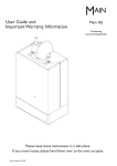
Kit Instructions
SolarfloTM
Evacuated Tube Collector
Facade Mounting
These instructions are for the collector mounting only and must be
used in conjunction with the
Evacuated Tube Collector Installation Guide
TM
Solarflo (Solar Thermal Domestic Hot Water System) should only
be installed by a competent person.
PLEASE LEAVE THESE INSTRUCTIONS WITH THE
USER FOR SAFE KEEPING.
© Baxi Heating UK Ltd 2008
© Baxi Heating UK Ltd 2008. All rights reserved. No part of this publication may be reproduced or
transmitted in any form or by any means, or stored in any retrieval system of any nature
(including in any database), in each case whether electronic, mechanical, recording or otherwise,
without prior written permission of the copyright owner, except for permitted fair dealing under
Copyrights, Designs and Patents Act 1988.
Applications for the copyright owner’s permission to reproduce or make other use of any part of
this publication should be made, giving any details of the proposed use to the following address:
The Company Secretary, Baxi Heating UK Ltd,The Wyvern Business Park, Stanier Way, Derby DE21 6BF.
Full acknowledgement of author and source must be given.
WARNING: Any person who does any unauthorised act in relation to a copyright work may be
liable to criminal prosecution and civil claims for damages.
2
© Baxi Heating UK Ltd 2008
CONTENTS
Section
1.0
2.0
3.0
4.0
5.0
© Baxi Heating UK Ltd 2008
General
Safety Information
Risk Assessments
Site Requirements
General Assembly Notes
Structure
Lightning protection
Connections
Collector Inclination
Solar Fluid
Installation of Solar Collector
Collector Orientation
Assembly of Kit
Facade (Por trait/Landscape)
Fitting the Tubes
Fitting the Connection Kit
Spare Parts
Notes
Page
4
6
8
13
14
3
1.0
1.1
General
Safety information
In order to reduce the number of deaths and major accidents
attributable to working at height, the Health and Safety
Executive has introduced comprehensive regulations and
guidance that should be followed by all businesses working at
height.
We consider in the following paragraphs some of the main
features of the regulations and guidance.This is, however, only a
limited summary and it is recommended that all businesses
planning on undertaking solar water heating installations obtain
a copy of the regulations and guidance issued by the Health
and Safety Executive and carefully consider the contents.
The regulations and guidance state that you are required to
carry out a risk assessment for all work conducted at height
and to put in place arrangements for:
• Eliminating or minimising risks from work at height.
• Safe systems of work for organising and performing work
at height.
• Safe systems for selecting suitable work equipment.
• Safe systems for protecting people from the consequences
of work at height.
The regulations and guidance highlight a hierarchy for safe
work at height:
• Avoid the risk by not working at height if practicable.
• Prevent falls, where it is not reasonably practicable to avoid
work at height; you are required to take suitable and
sufficient steps to prevent the risk of a fall including
selecting the most suitable work equipment (in accordance
with the regulations).
• Mitigate the consequences of a fall; where the risk of a
person or object falling still remains, take suitable and
sufficient measures to minimise the distance and
consequences of any fall.
Collective protection measures, such as guard rails on scaffold,
should be given priority over personal protection measures,
such as safety harnesses.
Within the regulations’ framework, you are required to:
a) Assess the risk to help you decide how to work safely.
b) Follow the hierarchy for safe work at height (i.e. avoid,
prevent and mitigate).
c) Plan and organise your work properly, taking account of
weather conditions and the possibility of emergencies.
d) Make sure those working at height are competent.
e) Make use of appropriate work equipment.
f) Manage the risks from working on or around fragile
surfaces and from falling objects.
g) Inspect and maintain the work equipment to be used and
inspect the place where the work will be carried out
(including access and egress).
When preparing to install a solar water heating system, it is
required that you perform a risk assessment in relation to
work at height and plan how you will organise your work,
taking into account the site, the weather conditions and the
experience and competence of colleagues or contractors who
may be working at height with you.
4
© Baxi Heating UK Ltd 2008
1.0
1.2
General
Risk Assessments
The HSE has published a number of very useful free
publications that advise how to undertake risk assessments.
Two of these that you should obtain are:
Five Steps to Risk Assessment.
A Guide to Risk Assessment Requirements.
The five steps outlined in the HSE leaflet are:
Step 1: Look for the hazards
This will mean looking at the site and identifying significant
hazards.These could be features such as a steep roof, a fragile
surface where the collectors may be mounted, uneven ground
or obstructions where access to the roof might be required.
Step 2: Decide who may be harmed and how
This might mean considering the particular risks that young
workers or trainees might face and thinking about the
residents of the household or visitors who could be hurt by
your activities.
Step 3: Evaluate the risks and decide which precautions should
be made.You should consider how likely it is that each hazard
will cause harm, decide which precautions you might take and
then assess, after you have taken those precautions, whether
the remaining risk will be high, medium or low. Where you
identify remaining risks, you should consider which further
action you could take to control the risks so that harm is
unlikely.
Step 4: Record your findings
If you have fewer than five employees you do not need to
write anything down, though it is useful to keep a written
record of what you have done. If you employ five or more
people you must record the significant findings of your
assessment.You must also tell your employees about your
findings.You need to be able to show that a proper check was
made, that you considered who might be affected, that you
dealt with all the obvious significant hazards, that the
precautions you propose are reasonable and that the
remaining risk is low.
Step 5: Review your assessment if necessary
Each solar water heating installation may bring its own
challenges and present its own particular hazards.You should
therefore be careful not to rely on a “standard” risk assessment
for installing a solar water heating system in a house, but
review the particular hazards for each new situation.The issue
of work equipment must be considered, but at the preparation
stage you should consider where scaffold or other access
equipment might be positioned and look out for any obvious
obstacles to this, such as a conservatory or porch.
In addition to the risks associated with work at height, you
should also consider the risks associated with lifting
and carrying solar collectors, using electric drills and using blow
lamps or blow torches for soldering.This is not an exclusive list
and you should consider all aspects of the proposed
installation to assess whether there are additional risks that
need to be taken into account.
© Baxi Heating UK Ltd 2008
5
2.0
2.1
Site Requirements
General assembly notes
These instructions relate to the installation of the SolarfloTM
Evacuated Tube Collector Facade Mounting. Refer to the parts
list to ensure the correct components are in the pack. All other
equipment must be installed as detailed in the SolarfloTM
Installation Guide.
Use only SolarfloTM mounting systems. Use of other
brackets/mounting systems will invalidate the warranty and may
result in an insecure and dangerous evacuated tube collector
installation.
Use only the corrosion resistant fastenings supplied. Holes
through any roof waterproofing materials should be sealed with
an appropriate UV and weather resistant sealant.
2.2
Structure
The collectors may only be mounted on sufficiently
load-bearing surfaces and substructures. It is essential that the
structural load-bearing capacity of the wall and the substructure
must be assessed before mounting the collectors. Particular
attention should be paid to the quality of the substructure in
terms of the stability of the screw joints necessary for installing
the collector mounting brackets. The structure must be able to
take the wind and snow loads that can occur. The assessment
should also take into account any special features of the
particular site that could lead to increased loads (air jets or eddy
formations, etc). If in doubt consult your builder.
2.3
Lightning protection / Equipotential bonding of
the building
It is not necessary to connect collector arrays to the lightning
protection of the building. For installations on metal
substructures at the installation site, authorised lightning
protection specialists must be consulted.The metal pipes of the
solar circuit must be earth bonded to the main earthing circuit
by means of a conductor (green/yellow) with a cross-section of
at least 6mm2.
6
© Baxi Heating UK Ltd 2008
2.0
2.4
Site Requirements
Connections
North
Ensure the sealing washer provided is inserted between the
male and female connections. All connecting pipe work and
fittings must be of a suitable metal; either copper, brass or
stainless steel. Soft soldered joints must not be used. Any seals
or sealing compounds must be resistant to temperatures of up
to 200°C and be resistant up to a 50% glycol/water mix.
Angle of tilt
90°
90°
80°
80°
70°
70°
60°
60°
50°
50°
40°
40°
30°
30°
20°
20°
10° 10°
West
East
When tightening the connections, always apply counterpressure with a wrench or another spanner to prevent
damage.
2.5
S.W.
The collector is suitable for angles of 0° or 90°.
The aspect should ideally face South, however
orientations between 30° East and 40° West of South are
acceptable. Fig. 1 shows the efficiency loss for varying angles of
inclinations and orientation (Portrait & Landscape).
S.E.
South
less than optimum by
0-5%
5-10%
Collector inclination for Facade Mounting
10-20%
2.6
Fig. 1
Solar fluid
The SolarfloTM collector tubes MUST be protected with the
supplied fluid. Top-ups cannot be made with water, only use
the fluid supplied (Tyfocor LS). Systems found to have lower
glycol concentrations will not be covered by the warranty.
170mm
170mm
2.7
Collector location
200mm
200mm
Under no circumstances should the collector be fitted where it
overhangs any part of the supporting structure.
Minimum clearances must also be adhered to for servicing and
or replacement of parts (see Fig. 2a).
120mm
Fig. 2a
© Baxi Heating UK Ltd 2008
7
3.0
3.1
Installation of Solar Collector
Collector Orientation
The facade mounted collector may be orientated portrait or
landscape to suit installation. Assess the location for installation
and determine which orientation is required (Fig. 2 or 3).
3.2
Assembly of Kit
Prior to installation check that the following packs are available
Manufacturer’s
Part No
Manifold Pack
1850mm
5130250
Tube Box (10 off)
(ensure enough boxes for installation)
5130222
Connection Kit
5130224
1200 - 1400mm (30 tubes)
Installation (Portrait)
Fig. 2
1850mm
900 - 1100mm (20 tubes)
1200 - 1400mmb (30 tubes)
Fig. 3
8
© Baxi Heating UK Ltd 2008
5130220
5130221
Facade Mounting Kit
900 - 1100mm (20 tubes)
Installation (Landscape)
20 tubes
30 tubes
3.0
3.3
Installation of Solar Collector
Facade (Portrait/Landscape)
1. Determine location for lower mounting bracket (Fig. 2 or 3).
Ensure that the material is suitable for the fixings supplied.
2. Attach lower brackets ensuring the correct centres and both
brackets are aligned and level (Fig. 6).
3. Determine location for upper mounting brackets (Fig. 2 or 3).
Attach upper mounting brackets ensuring correct centres and
both brackets are aligned and plumb to the lower brackets
(Diagonally measure between corners to check if plumb and
square).
5. Secure rails to brackets (Fig. 7).
Fig. 4
Fig. 5
Portrait
Landscape
Lower & Upper
Mounting Brackets
Fig. 6
Fig. 7
© Baxi Heating UK Ltd 2008
9
3.0
Support Rail
Top Clamp
Side Rail
3.3
Installation of Solar Collector
Facade (Portrait/Landscape) (cont)
NOTE: All side rails are supplied ready for portrait mounting.
For landscape mounting the locking pins must be fitted (Fig. 9).
a) Untighten the top clamp nut and remove.
b) Remove spring washer and flat washer.
c) Fit locking pin.
d) Refit spring washer and nut.
Support Rail
Support Rail
Bottom Clamp
Fig. 8
Manifold
Top Clamp
Mark and Drill hole
for Locking Pin
12. Locate the lower support rail and centralise on the side
rails. Slide the top clamp over the support rail to retain
(Fig. 8).
(Landscape)
Locking Pin
for Manifold
Fig. 9
(Landscape)
Support Rail
Bottom Clamp
Support Rail
Top Clamp
11. Loosen the lower support rail top clamps and slide away
from the support rail bottom clamp.
Manifold
Bottom Clamp
Locking Pin for
13. For landscape installations, mark the position for the locking
pin holes on the support rail. Drill holes 3mm diameter in the
correct location. Fit the locking pins and ensure full
engagement into the drilled holes (Fig. 9).
14.Tighten the top clamps fully and check the support rail is
secure.
15. Repeat 11 to 14 for the upper support rail.
Support Rail
(Landscape)
16. Loosen the manifold top clamps and slide away from the
manifold bottom clamp (Fig. 10).
17. Locate the manifold and centralise on the side rails and slide
the top clamp over the manifold to retain (Fig. 10).
18. For landscape installations mark position for the locking pin
holes on the manifold. Drill holes 3mm diameter in the correct
location. Fit the locking pins and ensure full engagement into
the drilled holes (Figs. 9 & 10).
19.Tighten the top clamps fully and check the manifold is
secure.
Manifold
Clamp
Fig. 10
Mark and Drill hole
for Locking Pin
(Landscape)
10
© Baxi Heating UK Ltd 2008
3.0
3.4
Installation of Solar Collector
Fitting the Tubes
1. Open manifold lid by removing front seal strip.
2. Open the tube retaining rubbers on the tube clip and place
the tube in the tube clips on both supports rails (Fig. 11).
3. Slide tube into manifold connection while slightly rotating
tube until washer on bellow sits flush against manifold fitting.
Do not apply force, if any problems check alignment of
support rails to manifold.
4. Insert tube retaining clip to secure tube to manifold (Fig. 12).
5. Gently pull on tube to ensure a secure assembly.
6. Close tube retaining rubber on both support rails. Repeat
steps 2 to 6 for all tubes.
7. Close manifold lid ensuring proper engagement of front seal
strip over whole length and on end caps.
Tube Retaining Clip
Tube Retaining Clip
Fig. 12
Front Seal Strip
Tube Clip
Manifold
Support Rail
Tube
Fig. 11
© Baxi Heating UK Ltd 2008
11
3.0
3.5
Installation of Solar Collector
Fitting the Connection Kit (Fig. 13)
1. Do not remove pipe clip.
2. Ensure clip is in the position shown.
3. Insert brass adaptor fully.
4. Push pipe clip in fully and check that the brass adaptor is
correctly retained..
5. Fit the sensor pocket to the compression elbow.
6. Fit compression elbow with sensor pocket and tighten the
union nut.
7. Fit the copper tail ensuring the pipe clip is in the open
position.
8. Push pipe clip in fully and check that the copper tail is
correctly retained.
9. Fit the air bleed fitting to the compression elbow.
10. Fit compression elbow and tighten the union nut.
Compression
Elbow
Copper Tail
Brass Adaptor
Compression Elbow
with Sensor Pocket
Fig. 13
12
© Baxi Heating UK Ltd 2008
4.0
Spare Parts
Short Parts List
A
C
D
K
F
G
Key
No.
Description
No.
Manufacturer’s
Part No.
A
Bracket Foot
5130637
C
Clamp Manifold Horizontal
5132704
D
Clamp Support Rail
5130641
F
Clip Manifold Connection
5130643
G
O-ring Manifold Connection
5130644
H
Clip Tube Retainer
5130645
J
O-ring Evac Tube
5130646
K
Clamp Rubber Evac Tube
5130647
L
DF100 Evac Tube 1off
5130648
M
Tee Piece Manifold
5132722
N
Fluid Tyfocor LS Solar 20Ltr
5130225
(Not Illustrated)
P
5132723
P
J
H
Sensor Pocket Manifold
M
L
© Baxi Heating UK Ltd 2008
13
5.0
14
© Baxi Heating UK Ltd 2008
Notes
5.0
© Baxi Heating UK Ltd 2008
Notes
15
All descriptions and illustrations provided in this leaflet have been carefully prepared but
we reserve the right to make changes and improvements in our products which may affect
the accuracy of the information contained in this leaflet. All goods are sold subject to our
standard Conditions of Sale which are available on request.
B AXI
A Trading Division of Baxi Heating UK Ltd (3879156),
A Division of Baxi Group.
Brooks House, Coventry Road,Warwick. CV34 4LL
Technical Enquiries 0844 8711525
Our contact centre is open Monday to Friday 8am to 6pm,
Weekends and Bank Holidays 8.30am to 2pm.
We are closed Christmas Day and New Years Day.
Website www.baxi.co.uk
e&oe
© Baxi Heating UK Ltd 2008
Comp No 5130231 - Issue 2 - 5/08