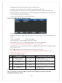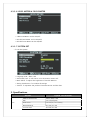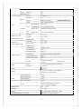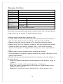
1
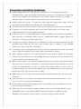
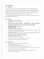
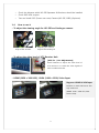
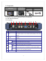
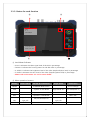
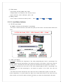
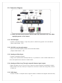
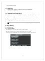
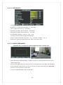
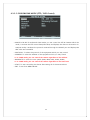
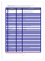
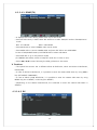
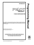
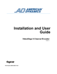
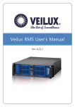
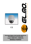
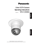
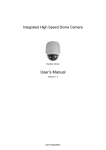
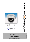
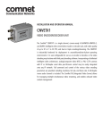
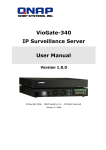
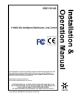
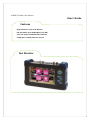
HYBRID Portable Test Monitor User's Guide Features High Resolution 7inch LCD Monitor HD-SDI INPUT (3G) HDMI INPUT (Full HD) Ultra-low power LED BACKLIGHT Monitor COAX (UP TO COAX) Remote Control Test Monitor Precaution and Safety Guidelines Please always handle the unit with care. Otherwise, the LCD display panel can be damaged when it gets any physical shock and/or you drop it to the ground. Please note that we may charge for the replacement of the display panel even the unit is under warranty, when it is broken due to any physical shock or user’s misuse. Avoid touching the screen. To clean the screen, wipe the screen with a clean, soft and dry towel and be careful not to damage the LCD display panel. To reduce the risk of fire or electric shock, do not expose the LCD to rain or moisture. Please do not connect the power wire to the video input/output port. It may cause malfunction when AC or DC power is inserted. Please use only the authorized battery charger included in the package. Otherwise, it may cause fire or explosion when using an unauthorized battery charger. (When red LED flicks in recharging, please request A/S) The built-in Li-Polymer battery (11.1V / 2200mA) is under six months warranty from the purchase date. Please do not use it with another type of battery on this portable monitor as it may cause fire or explosion. The battery can be damaged when a short circuit is created at the power connecting port or when the polarity of the power cable is connected in reverse. When supplying power to the camera through the test monitor, please use the power harness (DC jack) enclosed in the package. (we may charge you for the repairs if you cause a problem, using another jack) When supply power to the camera, please connect first the power cable to the camera and then turn on the unit. Otherwise, it may create a short circuit and the unit can be turned off automatically in order to protect the battery. When a short circuit is produced, please turn off the test monitor and then remove and re-insert the power harness (DC jack). Then turn the unit on again. Please keep the unit inside of the carrying bag in order to protect the LCD screen from scratches Please do not put the products on anything electrical conductive (screwdrivers, coins, iron, etc.) and not put them around water. If the product emits smoke, abnormal noise, or a strange odor, immediately turn it off and contact your distributor. When the unit is not working properly, please contact your distributor. Please do not disassemble the unit by yourself. (When unauthorized person modified or made damage on the product trying to repair it, we may charge you with the fee.) 1 1. Introduction 1-1. Overview Hybrid Test monitor is a multi-functional Analogue / HD-SDI / HDMI portable test monitor and this device can be used with various purposes such as checking video signal and cabling status with built-in video signal level meter (HD-SDI / Analogue), adjusting camera viewing angle and focusing, supplying power to camera, controlling PTZ for the speed dome camera and generating color pattern to the monitor, etc. Using this device, sole installer can check every parts of video surveillance system alone and complete every task easily. 1-2. Features • 7 inch Wide TFT-LCD Digital Panel • LED Back Light • Various input: HD-SDI (~3G), HDMI ( ~ 1080 P60), VGA ( ~ 1600 * 1200), CVBS • Various Output: HD-SDI (~3G, Loop Through), CVBS (Loop Through) • HD-SDI Video Signal Level Meter • HD-SDI Focus Meter • Analogue Video Signal Level Meter • P/T/Z control via RS-485 communication for speed dome cameras. (possible to add new protocols upon a customer’s request) • Coaxial communication (UP TO COAX) / Possible to control camera OSD menu / PTZ over coax cable in a far distance. (Max. 400m) • Supply power to the camera (DC-12V / 500mA) • HD-SDI, HDMI Audio output (Optional) • Leather bag and neck string for safety and convenience. • Li-polymer battery with 6~8 hours of productivity 1-3. Applications • Display the video signals or adjust the camera angles. • Check the cable status and/or DVR. • Check speed dome cameras, PTZ camera status or control PTZ. • Check the video level of each field and/or adjust the A. Level and F. Level of the UTP transmission solutions at its optimum level. • Control the OSD menu of a camera which supports coax communication. • Check HD-SDI, HDMI Signals. 2 • Check the distance which HD-SDI Repeaters & Receivers should be installed. • Check DVR VGA outputs • Test and install POC (Power over coax) Camera (HD-SDI, CVBS) (Optional) 1-4. How to use it • To adjust the viewing angle for HD-SDI and Analogue camera Adjusting the camera angle at the elevator Adjusting the camera angle at the Parking lot • To adjust the video level of UTP Receiver Hub [UTP Tx. / Rx. Adjustment] Useful features to adjust the video level of UTP receiver or to check the video signals of each surveillance areas. • HDMI (1920 x 1080 60P), UXGA (1600 x 1200) Video Input Supports HDMI & VGA Input Possible to check DVR menu with high resolution (HDMI: 1920 x 1080 P60, VGA: 1600 x 1200) 3 2. Components Accessories Leather Bag Main device Charge & Neck String Power harness & Power code 3. Product Parts and Peripheral Device Connection 3-1. Part name and function 3-1-1. Interface ① NO ② ③ ④ ⑤ ⑥ MARKING ⑦ ⑧ ⑨ ⑩ FUNCTION Charge the built-in Li-Polymer BATTERY (with exclusive charger) ① 12V Or, supply power to the camera (DC12V/500mA) with power harness. RS-485 communication for PTZ RECEIVER and SPEED DOME ② RS-485 ③ HDMI INPUT ④ ⑤ ⑥ HD-SDI CAMERA INPUT HD-SDI Signal Input (Max. resolution : ~3G ) OUTPUT HD-SDI Signal output (Loop Through) VGA INPUT ⑦ TERM ⑧ INPUT VIDEO ⑨ ⑩ OUTPUT POWER HDMI Signal Input (Max. 1920 x 1080P 60Hz) UXGA Input (Max. resolution: 1600 x 1200) With Loop through output : HI-Z position CVBS video signal input Coaxial communication: PTZ RECEIVER or SPEED DOME CAMERA CVBS Video signal output (Loop Through) Outputs Full color bar (pattern generator) Power switch (ON/OFF) 4 3-1-2. Button for each function ③ ④ HDMI 16 : 9 1920X1080p60 S.LVL: 90% Good FOCUS: 100 / 100 ① ② ① Level Meter Indicator • S.LVL: It indicates the video signal level of HD-SDI in percentage. • FOCUS: It indicates the focusing status for HD-SDI video in percentage. • A. LEVEL: It indicates the brightness level of the video (Amplitude/Sync level) in percentage • F. LEVEL: It indicates the color level of the video (Frequency/Burst level) in percentage. • Please refer to the menu 3-1-2-1 for more details. ② Menu operation buttons Button Camera Menu RS-485 & COAX Mode Angle Guide Video Input MODE PTZ&OSD Mode switch EXIT Operate in PTZ Mode MENU Operate in OSD MODE Menu ON ESC Operate in OSD MODE Menu OFF Multi Way Up, down, Key right, left ENTER Key ENTER Pan/Tilt/Zoom/Focus Source Change Angle Mode Out Up, down, right, left Select bar 5 HOT KEY(Zoom in) ③ Video status • Input Mode: HD-SDI, HDMI, VGA, CVBS • Display Mode: 4:3, Full(16:10), 16:9, Zoom1, Zoom2 • Input resolution: 1920 x 1080 p60 , NTSC , PAL ④ Battery status • Total 7 steps to indicate the battery status. 090% 070% 050% …… 3-1-2-1. Level Meter Indicator ① HD-SDI Level Meter • S. Level: It indicates HD-SDI signals in percentage. The closer to 100% the level is, the better the quality of the video is. And the lowest Video level is 6%. 0~30%: No Good / 31% ~ 60%: Normal / 60% ~: Good ② CVBS Level Meter • A. Level: It indicates the brightness of the video (Amplitude/Sync level) in percentage. The closer to 100% the level percentage is, the better the quality of the video is. When the A.Level % is under 100%, it indicates that the video signals are decreased and the brightness is reduced. • F. Level: It indicates the color level of the video (Frequency/Burst level) in percentage. The closer to 100% the level percentage is, the better the quality of the video color and the resolution is. • The video level meter indicates the sync and burst level of CVBS video signals in A.Level and F.Level respectively. It is useful when you adjust the A.Level and F.Level of the video from the video receiver over the UTP cable accurately and when you search the deteriorated video area. 6 0~60% : No Good / 60% ~ : Good ③ Focus Meter for HD-SDI camera and focus meter • Focus meter: It indicates the HD-SDI or Analogue Camera Focus in percentage. • It shows level of the focus (Min. 20 to Max. 255) depending on the level. 7 3-2. Connection Diagram ※ Please use the exclusive power harness cable only enclosed in the case when supplying power to the camera. 3-2-1. HD-SDI Input • Connect to HD-SDI camera / output the power to camera using power over coax feature. (Input data bitrate: ~3G) 3-2-2. HD-SDI Loop through output • Output the HD-SDI signal inputted from the HD-SDI camera (Output data bitrate: ~3G) 3-2-3. Analogue Video Input • Connect to Analogue Camera • Using Coax communication feature(Coaxitron), it is possible to control Camera OSD menu or PTZ of the Speed dome camera via coaxial cable. 3-2-4. Analogue Video Loop Through output & Pattern signal output • When the Pattern Out is off, V.OUT port outputs the video received from Analogue camera. • Select Pattern Out ON, V.OUT port outputs Full Color Bar to check the wiring status, monitor or DVR, etc. 3-2-5. VGA Input • Connect to DVR or Computer and It supports UXGA in maximum and higher resolutions may 8 not be displayed normally. 3-2-6. HDMI Input • Connect to DVR, Computer or other device which outputs HDMI signal. (Resolution: ~1080P 60Hz) 3-2-7. PTZ&OSD control through RS-485 • Connect to PTZ Receiver and/or SPEED DOME CAMERA as controller and also, connect to controller as PTZ receiver to check if the controller outputs data accurately. 3-2-8. Power Out(12VDC) • 12V input port can be use for both charging and outputting the 12VDC to the camera. However, the outputted power can be dropped up to 9VDC when the battery power level is low. 4. Menu Setting 4-1. MENU Mode 4-1-1. SELECT MENU - Press MENU Button and main menu will be displayed as below. - Press the direction buttons to mode Up ▲, Down ▼, Right ▶ or Left ◀. The menu mode is automatically off if you don’t press any buttons for a few minutes. 9 4-1-1-1. PICTURE SET • Contrast: To adjust the contrast range. (0~100 steps) • Brightness: To adjust the brightness. (0 ~ 100 steps) • Hue: To adjust the color (0 ~ 100 steps) • Saturation: To adjust the Chroma (0 ~ 100 steps) • Sharpness: To adjust the sharpness (0 ~ 50 steps) • Picture Mode: Standard > Movie > Vivid > User. The value of each mode changes automatically. • Scale: To adjust the screen ratio. (Full > 4 : 3 > Zoom1 > Zoom2 > 16 : 9) • Reverse: To reverse the upper and lower sides of the LCD screen. 4-1-1-2. ANGLE VIEW MODE Indication lines: To adjust the viewing angles based on a specific area. • When selecting the ANGLE MODE, it displays a green box and the indication lines of the camera angle zone.. • Press the SET MENU button to select the size of the green box. Press again the SET MENU button and select the side line of the box you want to adjust, and then press ◀/▶/▲/▼ buttons to set the position of each lines. • To exit the ANGLE MODE, press the EXIT KEY. 10 4-1-1-3. RS485&COAX MODE (PTZ / OSD Control) • MODE: In RS-485 Tx mode and COAX mode, you can control the PTZ & Camera OSD. In Rx. mode, it receives the PTZ control data (HEX value) and displays the data on the monitor. In Analyzer mode, it analyzes the protocols received through the RS-485 port and displays the HEX value and command. • PROTOCOL: To select the protocol of the equipment which you may control. • ADDRESS: To select the address of the equipment which you may control ※ In COAX mode, you can control the camera regardless of the address • BAUDRATE: To select the com. speed. (2400, 4800, 9600, 19200, 38400) ※ In COAX mode, you can control the camera regardless of the baud rate • START: To start controlling the device after setting all of the menus above. • EXIT: To exit from MENU MODE 11 ※ Built-in Protocol: Other protocols are available upon request in case that the camera manufacturers provide us with their protocols in advance.. NO COMPANY PROTOCOL PRODUCT MODEL DSC-300S/270S/230S Series (High Speed PTZ Dome Camera) 01 DONGYANG UNITECH (OSD) D-MAX DOH-240S Series (Speed PTZ Dome Camera) DPC-200 (Mini PTZ Dome camera) DRX-500, DRX-502A (CCTV PTZ receiver) 02 DONGYANG ELECTRONICS DY-255RXC DY-255RXC 03 FINE SYSTEM FineSystem CRR-1600i/s 04 INTER-M VRX-2201 VRX-2201 05 HONEYWELL(OSD) Honeywell HRX-2000, ScanDome-Ⅱ 06 LG MultiX(OSD) LG MultiX LPT-EP551PS/EI551PS/OS551HQ/OI551HQ/OI511HQ 07 LG LPT-A100L LG LPT-A100 LPT-A100L 08 PANASONIC(OSD) PanasonicC CS600, CS650, CS564, CS85X,… 09 PANASONIC PanasonicN CS564CS854/A,… 10 PELCO(OSD) Pelco-D … 11 PELCO(OSD) Pelco-P … Samsung SCC-641/3/07,…, SCC-64x Series Techwin SPD-xxxx Series 12 13 SAMSUNG ELECTRONICS (OSD) SAMSUNG TECHWIN (OSD) 14 SUNGJIN Sungjin RECEIVER/MPU 15 SYSMANIA Sysmania ORX-1000 16 VICON Vicon Stn V1311RB,V1310RB, V1200R-LM, etc. receivers 17 VICON Vicon Ext Surveyor Dome Series 18 Ikegami Ikegami35 PCS-35 19 Ikegami Ikegami358 PCS-358 20 NEW BORN HIGHTECH NEWBORN 21 TOKINA TOKINA DMP 22 Ernitec(OSD) ERNA BDR-51x,BDR-55x,BDR-575,ICU 23 BOSCH Bosch OSRD Receiver/Drivers, G1, G2, G3, VEZ, and G4 Series AutoDomes 24 GSP Systems CYBERSCAN1 25 Hitron Fastrax II Fastrax II (HID-2404) 26 YUJIN SYSTEMS Yujin Sys. EPT-5000S/6000S 27 Dynacolor DSCP Dyna. DSCP dynacolor DH801, DH701 and DH600 28 Ladon Ladon 29 HANIL STM MCU-1200N 30 LILIN_MLP2 LILIN_MLP2 31 LILIN_FastDome LILIN Fast 32 AMERICAN DYNAMICS AD SpdDome MCU-1200N, 1400N, 1500N ※ The protocols on companies marked with ‘(OSD)’ are available to controlling CAMERA OSD Menu. ※ Some protocols may not support the OSD menu control. 12 4-1-1-4-1. RS485(TX) • It displays the current setting mode at the top of the screen. • Press SET KEY shortly in MULTI WAY KEY selection to select PAN/TILT mode or ZOOM/FOCUS mode. - RED : P.T.Z MODE - BLUE : OSD MODE • Press Mode KEY to select CAMERA OSD control mode. • Press MENU KEY to control CAMERA OSD and press ESC KEY to exit OSD MENU In case of BOX/DOME Camera, Hold ENTER KEY to select OSD Menu • Press EXIT KEY to go to the previous mode. (In CAMERA OSD mode, switch to PAN/TILT mode first in order to exit.) • Press ◀/▶/▲/▼ buttons following the OSD guidance on the screen. ※ Cautions • The Hybrid Test monitor has 2 different PELCO-D PROTOCOL, which are PELCO-D PROTOCOL, PELCO(CNB). • In case of PELCO-D PROTOCOL, it is possible to enter the camera OSD menu by using MENU key. (SET PRESET COMMAND) • In case of PELCO (CNB) PROTOCOL, it is possible to enter the camera OSD menu by using MENU key (Go to PRESET) or ESC key (Run PRESET) • Depending on the camera manufacturer, the command to enter the camera OSD Menu is different. 4-1-1-4-2. RX 13 • It displays the current setting mode at the top of the screen. • It displays the connection status of RS-485 line indicated by HEX value. • The received data via RS-485 port can be displayed maximum in 8 lines in BYTE (16 byte). • When the data is more than 128 byte, it may be cleared out automatically. You can also clear it out temporarily, using the ESC button. • To go to the previous menu, press the EXIT button. 4-1-1-4-3.COAX [UP TO COAX] Control • It displays the current setting mode at the top of the screen.. • Press SET KEY shortly in MULTI WAY KEY selection to select PAN/TILT mode or ZOOM/FOCUS mode. - RED : P.T.Z MODE - BLUE : OSD MODE • Press Mode KEY to select CAMERA OSD control mode. • Press MENU KEY to control CAMERA OSD and ESC KEY to exit OSD MENU. In case of BOX/DOME Camera, Hold ENTER KEY to select OSD Menu • Press EXIT KEY to go to the previous mode. (In CAMERA OSD mode, switch to PAN/TILT mode first in order to exit.) • Press ◀/▶/▲/▼ buttons following the OSD guidance on the screen. ※ Possible to control the camera OSD menu in the remote side (Max. 400M) by Coax communication. (Standard of RG-6) • List of controllable models NO COMPANY Monitor OSD 01 Samsung Techwin PELCO-C 02 PELCO PELCO-C 03 DONGYANG UNITECH PELCO-C 04 Samsung E A1 CONTROLLABLE MODEL All models to support COAX communication (WINNER 5) All models to support COAX communication All models to support COAX communication (PIXIM) All models to support COAX communication ※ PELCO-C PROTOCOL in Hybrid Test monitor is compatible with all the product models above. Also, this product can control COAX in a remote side through the automatic NTSC/PAL recognition without any set-up. 14 4-1-1-4-4. ANALYZER • Using Analyzer mode, test monitor recognizes the received data packet and displays the address and command. • Addr : show the address. • Cmd : show the command. • Packet : show the Hex code of the received data. 4-1-1-5. PATTERN SET • It basically outputs the input signals through Video Out BNC but if you select “ON” on the CVBS Out in the pattern set menu, the selected pattern is outputted from Video out BNC. • It is possible to select one pattern among 10 types by user’s demand. 15 4-1-1-6. LEVEL METER & FOCUS METER • CVBS Level Meter can be ON/OFF. • HD-SDI Level Meter can be ON/OFF. • HD-SDI Focus Meter can be ON/OFF. 4-1-1-7. SYSTEM SET • To set the System • Language: KOR / ENG / JAP • OSD Dwell Time: To set time to turn the monitor menu OFF • BACK LIGHT: To adjust the brightness of the LED Monitor. • Setting Initialization: To initialize all settings. • Version: To represent the product Firmware version and the date. 5. Specifications MODEL LCD Hybrid Test monitor DISPLAY RESOLUTION 1280 X (RGB) X 800 SIZE 6.95 inch(diagonal) PIXEL PITCH 0.117mm(H) X 0.177mm(V) BRIGHTNESS(cd) Min.:340, Nor.:400 Contrast Ratio Min.:600, Nor.:800 16 Viewing Horizontal 89° Angle Vertical 89° RESPONSE (ms) INPUT HDMI ~1080p 60 HD-SDI ~3G CVBS NTSC/PAL 1.0Vp_p, XVGA Max. 1600x1200, 60Hz VIDEO CVBS OUTPUT HDSDI RANGE FOR CVBS VIDEO SIGNAL LEVEL RANGE FOR HD-SDI SIGNAL LEVEL CONNECT PORT PATTERN ON Color Bar PATTERN OFF Loop Through Output VIDEO OUT NTSC/PAL 1.0Vp_p(75Ω시) VIDEO OUT ~3G, LOOP THROUGH COAX Communication A LEVEL 10 ~ 118% F LEVEL 20 ~ 120% ERROR RATE ±2% SDI LEVEL 10 ~ 100% Focus LEVEL 20 ~ 255 ERROR RATE - HDMI INPUT HDMI C Type F HD-SDI INPUT BNC-F HD-SDI OUTPUT BNC-F VGA INPUT D-SUB 15Pin RIGHT ANGLE TYPE CVBS Video Input: BNC-F CVBS Video Output BNC-F RS-485 POWER 11 Pan/Tilt/Zoom/Focus Control OSD Control INPUT DC 12.6V(exclusive Adapter included) OUTPUT ≒ DC 12V COLOR Dark Gray 2 units of Li-Polymer: 11.1V, 2200mA BATTERY (protection circuit applied) With HDMI input 6.5W With HD-SDI input 7.5W POWER With VGA Input 6.5W CONSUMPTION With CVBS Input 6.5W VP On Different depending on cameras (Do not use PTZ Cameras) TEMPERATURE 0℃ ~ +50℃ HUMIDITY 0% ~ 80% WEIGHT SET : 920g , BAG : 640g Total : 1.6kg DIMENSION(WITHOUT THE BAG) 240.9(W) X 153.4(H) X 50(D)mm 17 Warrantee Certificate Product Name Model No. Date of Purchase Place of Purchase Customer Distributor Warranty Period Name Contact info. Name Contact info. 1 Year from the date of purchase This product has passed thorough quality control and test, and if this gets broken during normal use, we provide 12 months warranty service. • Please check this warranty indication first. • For any defect under normal use within the warranty service period, we give you free repair service according to the warranty certificate. • Please contact the number stated on the backside regarding repairs. • Please inform us of the product’s model No. and more details on faulted conditions when you report a problem. Also, if you know the name, division of the person in charge of the service, it is more convenient for you. • Please read the user’s manual before reporting a problem. • The specification is subject to change without any notice in advance, for its quality improvement. • Despite of free warranty service period, we charge you for the repairs in the cases below: - When an unauthorized person made damage on the product, trying to repair it. - Breakage or trouble made by wrong power or frequency. - When you want to reassemble for full system or replace parts within warranty service period. - Breakage or trouble by natural disasters (fire, flood, tsunami, etc.) 18 [MEMO] 19