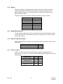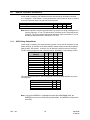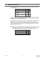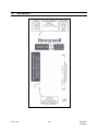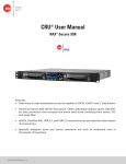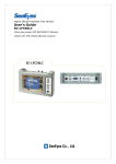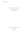
1
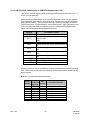
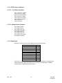
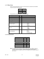
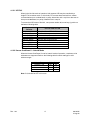
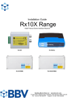
HVBPIT44
Protocol Translator
User Manual
900.0595 – August 2006 - Rev. 1.04
ISSUE
DATE
REVISIONS
HVBMU001142-B
A
July 2005
B
August 2005
Initial Release (PCN1880) (EC03467)
Revise description of power supply, part number 8491930089 to 100-240Vac (from 90-260Vac) (EC03467)
900.0595
1.0
October 2005
1.01
November 2005
1.02
January 2006
1.03
March 2006
Add switch setting for HCC745 camera OSD
1.04
August 2006
Add switch settings for addressing Korean ScanDome II –
Intervid protocol; add switch settings for PTZ logical address
ranges; firmware revision 3.02.
Rev. 1.04
Revise connections and transfer document control to Agile.
Add switch setting for Javelin 308
Add switch settings for Kalatel speed dome and Honeywell
Korean Scan dome; updated VCL AUX functions
ii
900.0595
3-Aug-06
Rev. 1.04
iii
900.0595
3-Aug-06
FCC COMPLIANCE STATEMENT
INFORMATION TO THE USER: This equipment has been tested and found to comply
with the limits for a Class A digital device, pursuant to part 15 of the FCC rules. These
limits are designed to provide reasonable protection against harmful interference when
the equipment is operated in a commercial environment. This equipment generates,
uses, and can radiate radio frequency energy and, if not installed and used in
accordance with the instruction manual, may cause harmful interference to radio
communications. Operation of this equipment in a residential area is likely to cause
harmful interference in which case the user will be required to correct the interference at
his own expense.
CAUTION: Changes or modifications not expressly approved by the party responsible
for compliance could void the user’s authority to operate the equipment.
CANADIAN COMPLIANCE STATEMENT
This Class A digital apparatus complies with Canadian ICES-003.
Cet appareil numérique de la Classe A est conforme à la norme NMB-003 du Canada.
USERS OF THE PRODUCT ARE RESPONSIBLE FOR CHECKING AND
COMPLYING WITH ALL FEDERAL, STATE, AND LOCAL LAWS AND
STATUTES CONCERNING THE MONITORING AND RECORDING OF
VIDEO AND AUDIO SIGNALS. HONEYWELL VIDEO SYSTEMS SHALL
NOT BE HELD RESPONSIBLE FOR THE USE OF THIS PRODUCT IN
VIOLATION OF CURRENT LAWS AND STATUTES.
Rev. 1.04
iv
900.0595
3-Aug-06
IMPORTANT SAFEGUARDS
1.
READ INSTRUCTIONS – All safety and operating instructions should be read before the unit is
operated.
2.
RETAIN INSTRUCTIONS – The safety and operating instructions should be retained for future
reference.
3.
HEED WARNINGS – All warnings on the unit and in the operating instructions should be adhered
to.
4.
FOLLOW INSTRUCTIONS – All operating and use instructions should be followed.
5.
CLEANING – Unplug the unit from the outlet before cleaning. Do not use liquid cleaners or
aerosol cleaners. Use a damp cloth for cleaning.
6.
ATTACHMENTS – Do not use attachments not recommended by the product manufacturer as
they may result in the risk of fire, electric shock, or injury to persons.
7.
WATER AND MOISTURE – Do not use this unit near water or in an unprotected outdoor
installation, or any area which is classified as a wet location.
8.
POWER SOURCES – This product should be operated only from the type of power source
indicated on the marking label. If you are not sure of the type of power supplied to your facility,
consult your product dealer or local power company.
9.
GROUNDING – This unit must be connected to a good earth ground.
10.
OVERLOADING – Do not overload outlets and extension cords as this can result in a risk of fire or
electric shock.
11.
POWER-CORD PROTECTION – Power supply cords should be routed so that they are not likely
to be walked on or pinched by items placed upon or against them, paying particular attention to
cords and plugs, convenience receptacles, and the point where they exit from the monitor.
12.
OBJECT AND LIQUID ENTRY – Never push objects of any kind into this unit through openings as
they may touch dangerous voltage points or short-out parts that could result in a fire or electric
shock. Never spill liquid of any kind on the unit.
13.
SERVICING – Do not attempt to service this unit yourself as opening or removing covers may
expose you to dangerous voltage or other hazards. Refer all servicing to qualified service
personnel.
14.
DAMAGE REQUIRING SERVICE – Unplug the unit from the outlet and refer servicing to qualified
service personnel under the following conditions:
a. When the power-supply cord or plug is damaged.
b. If liquid has been spilled, or objects have fallen into the unit.
c.
Rev. 1.04
If the unit has been exposed to rain or water.
v
900.0595
3-Aug-06
IMPORTANT SAFEGUARDS, CONTINUED
d. If the unit does not operate normally by following the operating instructions. Adjust only those
controls that are covered by the operating instructions as an improper adjustment of other
controls may result in damage and will often require extensive work by a qualified technician to
restore the unit to its normal operation.
e. If the unit has been dropped or the enclosure has been damaged.
f.
When the unit exhibits a distinct change in performance - this indicates a need for service.
15.
REPLACEMENT PARTS – When replacement parts are required, be sure the service technician
has used replacement parts specified by the manufacturer or have the same characteristics as the
original part. Unauthorized substitutions may result in fire, electric shock or other hazards.
16.
SAFETY CHECK – Upon completion of any service or repairs to this unit, ask the service
technician to perform safety checks to determine that the unit is in proper operating condition.
17.
LIGHTNING AND POWER LINE SURGES – For added protection of this unit when it is left
unattended and unused for long periods of time, unplug it from the wall outlet and disconnect the
cable system. This will prevent damage to the unit due to lightning and power-line surges.
18.
HEAT – The product should be situated away from heat sources such as radiators, heat registers,
stoves, or other products (including amplifiers) that produce heat.
19.
INSTALLATION – Do not install the unit in an extremely hot or humid location, or in a place
subject to dust or mechanical vibration. The unit is not designed to be waterproof. Exposure to
rain or water may damage the unit.
20.
WALL OR CEILING MOUNTING – The product should be mounted to a wall or ceiling only as
recommended by the manufacturer
Rev. 1.04
vi
900.0595
3-Aug-06
EXPLANATION OF GRAPHICAL SYMBOLS
The lightning flash with arrowhead symbol within an equilateral triangle is intended to
alert the user to the presence of uninsulated "dangerous voltage" within the product's
enclosure that may be of sufficient magnitude to constitute a risk of electric shock to
persons.
The exclamation point within an equilateral triangle is intended to alert the user to the
presence of important operating and maintenance (servicing) instruction in the literature
accompanying the product.
CAUTION
CAUTION
RISK OF ELECTRIC SHOCK
DO NOT OPEN
CAUTION: TO REDUCE THE RISK OF ELECTRIC SHOCK,
DO NOT REMOVE COVER (OR BACK).
NO USER-SERVICEABLE PARTS INSIDE.
REFER SERVICING TO QUALIFIED SERVICE PERSONNEL.
WARNINGS
WARNING: TO REDUCE THE RISK OF FIRE OR ELECTRIC SHOCK, DO
NOT EXPOSE THIS PRODUCT TO RAIN OR MOISTURE.
WARNING: DO NOT INSERT ANY METALLIC OBJECT THROUGH
VENTILATION GRILLS .
WARNING: THIS UNIT MUST BE PROPERLY GROUNDED. NONOBSERVANCE OF THIS STANDARD PRACTICE MAY RESULT IN A
STATIC ELECTRICITY BUILD-UP THAT MAY RESULT IN AN ELECTRIC
SHOCK WHEN EXTERNAL CONNECTIONS ARE TOUCHED.
Rev. 1.04
vii
900.0595
3-Aug-06
Notes:
Rev. 1.04
viii
900.0595
3-Aug-06
TABLE OF CONTENTS
1.1
INTRODUCTION ........................................................................................................................... 1
2.1
OPERATION.................................................................................................................................. 1
3.1
SWITCH SETTINGS...................................................................................................................... 3
3.1.1 Address Selection............................................................................................................ 3
3.1.2 PTZ Logical Address Ranges .......................................................................................... 3
3.1.3 Baud Rate Selection ........................................................................................................ 4
3.1.4 Input Protocol Selection .................................................................................................. 4
3.1.5 Output Protocol Selection ............................................................................................... 4
3.1.6 Auto Home Positioning.................................................................................................... 5
3.1.7 Write Protecting Home Position....................................................................................... 5
4.1
PTZ MODE DEVICE SPECIFIC OPERATION ............................................................................... 7
4.1.1 Diagnostic Mode.............................................................................................................. 7
4.1.2 Honeywell/GYYR CONTROLINK...................................................................................... 7
4.1.3 VCL .................................................................................................................................. 7
4.1.4 Molynx.............................................................................................................................. 8
4.1.5 Baxall ZTX3 and ZTX4 ..................................................................................................... 8
4.1.6 Burle TC7400 Series Dome ............................................................................................. 8
4.1.7 Pelco ‘D’ and ‘P’ .............................................................................................................. 8
4.1.8 Diamond Protocol (KD6/HD6 Series) .............................................................................. 9
4.1.9 Hitachi CD-08 / Mitsubishi CCD-300E Cameras.............................................................. 9
4.1.10 JAI CV-S2500 Camera (prior to HVBPIT44 firmware rev. 2.78)..................................... 10
4.1.11 Sensormatic RS422 Dome Protocol.............................................................................. 11
4.1.12 JVC TK-C675 Dome....................................................................................................... 12
4.1.13 Dennard RS422 Dome Protocol .................................................................................... 12
4.1.14 Plettac SVD106 / SVD106A............................................................................................ 12
4.1.15 GYYR Vortex .................................................................................................................. 13
4.1.15.1 Standard Operation ........................................................................................ 13
4.1.15.2 Tour Define Operation..................................................................................... 14
4.1.15.3 Menu Access Operation.................................................................................. 14
4.1.16 Kowa Dome ................................................................................................................... 14
4.1.17 Mikami Dome................................................................................................................. 15
4.1.18 Pacom Protocol ............................................................................................................. 15
4.1.19 Panasonic WV-CS600, CS650....................................................................................... 16
4.1.20 Vicon .............................................................................................................................. 16
4.1.21 HCC745 ......................................................................................................................... 17
4.1.22 Korean ScanDome II – Intervid Mode............................................................................ 17
5.1
DEVICE CONTROL INTERFACE ................................................................................................ 18
5.1.1 ASCII String Output Mode ............................................................................................. 18
6.1
ALARM CONCENTRATOR.......................................................................................................... 19
Rev. 1.04
ix
900.0595
3-Aug-06
TABLE OF CONTENTS, CONTINUED
7.1
CONNECTIONS.......................................................................................................................... 20
7.1.1 Power Connection ......................................................................................................... 20
7.1.2 Slave Channel................................................................................................................ 20
7.1.3 Master Channel.............................................................................................................. 21
7.1.4 I2C Expansion Connection............................................................................................. 21
8.1
MECHANICAL ............................................................................................................................. 22
9.1
SPECIFICATIONS ....................................................................................................................... 23
Rev. 1.04
x
900.0595
3-Aug-06
1.1
INTRODUCTION
The HVBPIT44 Protocol Interface Translator (PIT) converts Honeywell’s BossWare serial
command protocol to various protocols compatible with equipment from other
manufacturers.
The PIT has two serial communications ports. The RS422/RS485 “Slave” port connects
to the BossWare communications loop and interprets the telemetry control messages.
The RS422/RS485 “Master” port connects to the other manufacturer’s equipment.
The PIT may be configured to operate in various modes:
2.1
•
In Pan/Tilt/Zoom (PTZ) mode, the BossWare PTZ control messages are received
on the “Slave” communications port. Depending on the DIP switch settings,
these commands are then translated to serial data packets which are
compatible with other manufacturer’s Pan/Tilt/Zoom telemetry receivers or
integrated domes.
•
In device control mode, generic BossWare device control commands are
received and translated into data packets compatible with other manufacturer’s
VCR’s, Multiplexers, Quad’s, etc.
•
In Alarm Concentrator mode, alarm inputs and system outputs may be
connected via the I2C expansion port on the PIT. This allows for the connection
of up to 256 remote alarms into a system and also for up to 256 system outputs.
In device control mode, the PIT receives generic device control commands from
the system main controller.
OPERATION
On power up, both the slave channel and the master channel LEDs will be illuminated.
The PIT unit receives serial messages from the system master controller, via its slave
communication port. When a valid message is received, the slave port LED will flash
off briefly to indicate message receipt. Only messages addressed to the unit address
set up on DIP switch 2 will be received. Should DIP switch 2 be set to zero (all switches
off), then messages addressed to any PTZ unit will be received by the PIT. The
received PTZ control message will then be translated into the appropriate command,
compatible with the PTZ equipment selected by means of DIP switch 3. This
message will be transmitted out of the master port to one or more PTZ telemetry
receivers/domes, which may be attached to this port. When the message is transmitted,
the master port LED will flash off briefly.
When the PTZ unit does not support addressing (e.g. Mitsubishi RS232 camera),
then one PIT is required per PTZ. The various PTZ units in a system may be
individually controlled by setting the address switch on the PIT. When the PTZ unit
supports addressing (e.g. VCL domes), then the PIT may be set to address zero
(broadcast) and each PTZ unit on the master communication port must be set to a
unique address. There is no limitation in mixing PTZ units/domes from different
manufacturers as long as the above requirements are met and there is at least one PIT
per translation type.
Rev. 1.04
1
900.0595
3-Aug-06
2.1 OPERATION, CONTINUED
Should an installation require one or more PIT units for protocol translation, this has no
effect on the connection/operation of standard PTZ units, which are compatible with the
“native” RS422 protocol generated by the master controller.
Should it be required to use features such as auto-homing, only on specific PTZ units,
then these units must be attached to a PIT, which is set up for the required features.
Other PTZ units, which do not require this feature, must be attached to the master
port of a separate PIT, in which this feature is disabled. In such a system, each PTZ
unit must be at a unique address in order for the master controller to be able to
control it independently.
The PIT takes care of translating fixed speed commands into variable speed
commands, which are automatically ramped from slow to high speed, when the PTZ
unit supports variable speed. Similarly, variable speed commands are translated into
fixed speed commands where the PTZ unit does not support variable speed.
The PIT allows for I2C alarm input expansion modules to call preset positions on
attached PTZ units. The I2C unit set to address 8 causes PTZ 1 to move to preset
positions 1 to 16 when the corresponding inputs are activated by the closing of an
external contact. I2C expansion unit address 9 operates PTZ 2, etc. I2C expansion
unit address 16 operates PTZ 8, allowing for a maximum of 8 PTZ units to be
controlled by the I2C expansion modules in this manner.
Rev. 1.04
2
900.0595
3-Aug-06
3.1
SWITCH SETTINGS
To access the configuration switches, the two screws on the top cover of the PIT must
be removed. The legend on the cover shows the switches as S1, S2 and S3. Each of
these switch groups has 8 individual switches, marked as 1 through 8. Individual
switches are referred to by the switch group, followed by the switch number. e.g.
S1/8. The switch settings defined in this manual are firmware revision 3.02.
3.1.1
Address Selection
Set switch 2 to the required address of the PIT. This usually matches the camera number
in the system. The actual switch setting is the binary representation of the address.
Certain protocols allow for the addressing of multiple devices on the master
communications port (Broadcast mode). In this case, this DIP switch may be set to
address zero, which will pass all received messages through from the slave to the
master port. The following table shows the first few addresses:
Address
Switch
Legend
S2/8
S2/7
S2/6
S2/5
S2/4
S2/3
S2/2
S2/1
Address 7 Address 6 Address 5 Address 4 Address 3 Address 2 Address 1 Address 0
0 (B/cast)
Off
Off
Off
Off
Off
Off
Off
Off
1
Off
Off
Off
Off
Off
Off
Off
On
2
Off
Off
Off
Off
Off
Off
On
Off
3
Off
Off
Off
Off
Off
Off
On
On
4
Off
Off
Off
Off
Off
On
Off
Off
5
Off
Off
Off
Off
Off
On
Off
On
6
Off
Off
Off
Off
Off
On
On
Off
On
On
On
On
On
On
On
On
…
255
Note: There is one exception to input protocol. When the input address is set to 255, the
PIT will receive 8 bit data and operate in broadcast mode.
3.1.2
PTZ Logical Address Ranges
Switch 3, positions 5 and 6, are used to support below PTZ logical address
ranges.
PIT No.
1
2
3
4
Rev. 1.04
S3/6
Off
Off
On
On
S3/5
Off
On
Off
On
Logical Address Type in VideoBlox
Range
Confiurator
1 - 255
PTZ
257 - 511
PTZ(Type2)
513 - 767
PTZ(Type3)
769 - 1023
PTZ(Type4)
3
900.0595
3-Aug-06
3.1.3
Baud Rate Selection
Switch 3, positions 7 and 8, are used to set the slave port baud rate as per the following
table:
3.1.4
Baud Rate
S3/8
S3/7
1200 baud
Off
Off
9600 Baud
Off
On
19.2 Kbaud
On
Off
57.6 Kbaud
On
On
Input Protocol Selection
Switch 3, positions 1 to 4 are used to set the protocol, which the PIT expects to receive
on its slave communications port.
Input / Received Protocol Compatible With
S3/4
S3/3
S3/2
S3/1
Reserved
Off
Off
Off
Off
BossWare (first group)
Off
Off
Off
On
BossWare (second group)
Off
Off
On
Off
Reserved
Off
Off
On
Off
Device Control Interface
On
On
On
Off
Alarm Concentrator
On
On
On
On
Reserved, binary values 3 to 14
3.1.5
Output Protocol Selection
Switch 1, positions 1 to 4, are used to set the protocol the PIT will transmit on its master
communications channel.
Note: The group selection must be carried out as described under “Input Protocol
Selection”.
Output / Transmitted Protocol Compatible With
Text/diagnosis output
Honeywell/GYYR Vortex
Honeywell VCL Dome (VCLTP)
Molynx (Visilynx)
Baxall (ZTX3 / ZTX4)
Burle TC7400 AutoDome
Pelco Intercept “D” & “P”
Honeywell Ultrak/Diamond
Hitachi CD-08 / Mitsubishi CCD-300E Cameras
JAI SV-2500 (prior to HVBPIT44 firmware rev. 2.78)
Kalatel Dome (HVBPIT44 firmware rev. 2.78 or later) 1
Sensormatic RS422
JVC TK-C675
Group S1/4 S1/3 S1/2 S1/1
First
First
First
First
First
First
First
First
First
First
First
First
First
Off
Off
Off
Off
Off
Off
Off
Off
On
On
On
On
On
Off
Off
Off
Off
On
On
On
On
Off
Off
Off
Off
Off
Off
Off
On
On
Off
Off
On
On
Off
Off
Off
On
On
Off
On
Off
On
Off
On
Off
On
Off
On
On
Off
On
1
To control the Kalatel dome with the HVBPIT44, use Firmware Ver. 2.99
Rev. 1.04
4
900.0595
3-Aug-06
3.1.5
Output Protocol Selection, Continued
Output / Transmitted Protocol Compatible With
Ernitec ERNA protocol
Samsung SPP-12
Dennard
Mark Mercer
Honeywell Korean Dome (HSDN-251) 2
Plettac SVD106/SVD106A
Teljoy
AD Biphase
Gyyr Vortex
Kowa Dome
Mikami Dome
Pacom
Panasonic CS600 / CS650
Vicon
Javelin 308
HCC745
3.1.6
Group S1/4 S1/3 S1/2 S1/1
First
On On Off Off
First
On On Off On
First
On On On Off
First
On On On On
Second On Off On On
Second Off Off Off Off
Second Off Off Off On
Second Off Off On Off
Second Off Off On On
Second Off On Off Off
Second Off On Off On
Second Off On On Off
Second Off On On On
Second On Off Off Off
Second On Off Off On
Second On On Off On
Auto Home Positioning
All PTZ units which support preset positioning may take advantage of auto-homing
when used in conjunction with the PIT. To use this feature, switch 1, positions 6 to 7 are
used as follows:
Should an auto-home time-out value be set, the PTZ will automatically be caused to
return to preset position 1 after the expiration of the time-out. The time-out is calculated
from the time the PTZ was last moved.
3.1.7
Auto Home Time-out
S1/7
S1/6
Auto-homing disabled
Off
Off
15 seconds
Off
On
1 minute
On
Off
3 minutes 45 seconds
On
On
Write Protecting Home Position
The home position may be write-protected by switching SW1/8 on. In this mode, it is not
possible to modify preset position 1.
2
To control the Honeywell Korean dome with the HVBPIT44, use Firmware Ver. 3.00 or later.
Rev. 1.04
5
900.0595
3-Aug-06
Notes:
Rev. 1.04
6
900.0595
3-Aug-06
4.1
PTZ MODE DEVICE SPECIFIC OPERATION
4.1.1
Diagnostic Mode
In this mode of operation, every PTZ control command received is converted into a
readable text string. This string is transmitted out of the PIT master communications
port at 9600 baud, no parity, 8 data bits and 1 stop bit.
4.1.2
Honeywell/GYYR CONTROLINK
In this mode of operation, the PIT generates output data which will control either the
Honeywell PTZC or the GYYR ControLink RD. This mode is used to convert from
BossWare 9 bit mode, to 8 bit PC compatible mode, or to change the communication
baud rate.
Note: The additional functions such as PTZ home positioning are NOT implemented in
this mode.
Output Baud Rate
S1/6
S1/5
1200 baud
Off
Off
2400 baud
Off
On
9600 baud
On
Off
19.2 Kbaud
On
On
The output data may be in standard BossWare compatible mode (9-bit data
transmission) or 8-bit mode, which is more compatible with PCs
Output Data Format
S1/8
8 Bit PC compatible data
Off
9 Bit BossWare compatible data On
4.1.3
VCL
The VCL auxiliaries for this dome have been assigned the following functions by the PIT:
Keyboard Function
Aux 1
Aux 2
Aux 3
Aux 4
Aux 5
Aux 6
Aux 7
Aux 8
Rev. 1.04
VCL Function
Operates the 180 degree turn
function
Turns auto focus on
Recalls alarm preset position (high
speed)
Saves alarm preset position
Operates the Washer function
Operates the Wiper function
Toggles mono/color
Turns auto mono/color on
7
900.0595
3-Aug-06
4.1.4
Molynx
When set for Molynx compatible protocol output, switch1/5 is used to set fixed
speed/variable speed control. When this switch is off, full variable speed control is
allowed. When this switch is on, only fixed speed commands are transmitted to the
Molynx telemetry receiver.
The auxiliary outputs are mapped to the Molynx telemetry receiver as follows:
Keyboard Function Molynx Function
Aux 1
Aux 1
Aux 2
Aux 2
Aux 3
Wash
Aux 4
Wipe
Aux 5
Lamps
Aux 6
Lens slow
Aux 7
Camera
Aux 8
Home
4.1.5
Baxall ZTX3 and ZTX4
The PIT generates data for this protocol at 1200 baud. Ensure that the telemetry receiver
is set for this data rate. The first 8 preset positions are supported for receivers which
support this function.
4.1.6
Burle TC7400 Series Dome
When in the Burle mode of operation, the output baud rate may be set by means of DIP
switch S1/5.
Master (Output) channel Baud Rate
9600 Baud
2400 Baud
4.1.7
S1/5
Off
On
Pelco ‘D’ and ‘P’
In Pelco ‘D” mode of operation, 255 addresses are supported. Setting DIP 1/8 on
selects Pelco ‘P’ mode. In ‘P’ mode, the adjacent table shows the selection of the valid
address range.
Rev. 1.04
Address Range
S1/6
S1/5
Address 1 to 32
Off
Off
Address 33 to 64
Off
On
Address 65 to 96
On
Off
Address 97 to 128
On
On
8
900.0595
3-Aug-06
4.1.8
Diamond Protocol (KD6/HD6 Series)
When in the Diamond mode of operation, only 8 cameras may be controlled by a
single PIT in broadcast mode. Selection of which group of 8 cameras may be carried out
by means of DIP switch S1.
For any address outside of this range, a dedicated PIT per Diamond dome would be
required.
Valid Addresses in Broadcast Mode
Address 1 to 8 inclusive
Address 9 to 16 inclusive
Address 17 to 24 inclusive
Address 25 to 32 inclusive
Address 33 to 40 inclusive
Address 41 to 48 inclusive
Address 49 to 56 inclusive
Address 57 to 64 inclusive
S1/7 S1/6 S1/5
Off
Off
Off
Off
Off
On
Off
On
Off
Off
On
On
On
Off
Off
On
Off
On
On
On
Off
On
On
On
Various additional functions of the Diamond dome are:
Aux Output
1 to 8
9
10 to 19
20
21
22
23
24
25
26
27
28
29
31 to 40
41 to 50
51
52
53
54
55
4.1.9
Function
Operate dome Aux Output
Invoke KD6/HD6 Setup Menu
Numeric ‘0’ through ‘9’
Enter key
Escape key
Program Preset Menu
Program Vectorscan Menu
List Preshots
Run Vectorscan Once
Continuous Vectorscan
Go to PreShot
Display On/Off
Coordinate Display On/Off
Continuous VectorScan 1 to 10
Vectorscan Once 1 to 10
Key ‘E’
Key ‘C’
Key ‘D’
Key ‘S’
Key ‘N’
Hitachi CD-08 / Mitsubishi CCD-300E Cameras
Full functionality of zoom, focus, iris and preset positioning is supported when used in
conjunction with the PIT. Obviously, as the camera does not incorporate a pan / tilt
head, these functions are not available.
Rev. 1.04
9
900.0595
3-Aug-06
4.1.10 JAI CV-S2500 Camera (prior to HVBPIT44 firmware rev. 2.78)
This camera does not support preset positioning and therefore the description in 3.1.5
and 3.1.6 is not applicable.
SW1/8 is used to prevent access to the camera configuration menu from the standard
control keyboard. If this switch is in the off position, then the menu may be invoked by
storing preset position 1. The up/down/left and right arrow keys then allow selection of
various menu items. To leave the menu, store preset position 1 again. This switch being
in the on position also limits the operator’s access to certain functions as described
below. The following table lists the keyboard functions:
Keyboard
Function
Iris [C]
Iris [O]
Aux 1
Aux 2
Aux 3
Aux 4
Aux 5 – AutoPan
Aux 6 - PTZ F1
Aux 7 - PTZ F2
Aux 8 - PTZ F3
Jai Camera Function
Selects AGC
Selects manual gain control mode with
maximum gain
(255)
Selects AGC
Selects manual gain control mode with gain of
50
Selects manual gain control mode with gain of
100
Selects manual gain control mode with gain of
150
Selects manual gain control mode with gain of
200
Switches off backlight compensation
Selects backlight compensation pattern 1
Selects backlight compensation pattern 1
Additional functions may be accessed by recalling preset positions as per the following
table. These functions may also be accessed by operating the auxiliary output from the
control system.
Note: Aux 1 to 8 operate as described above.
Access
Preset
Aux
Controlled
Number
Access
By S1/8
1
No
N/A
2
No
N/A
3
No
N/A
4
No
N/A
5
No
N/A
6
No
N/A
7
No
N/A
8
No
N/A
Rev. 1.04
10
Jai Camera Function
Manual gain set to 0
Manual gain set to 50
Manual gain set to 100
Manual gain set to 150
Manual gain set to 200
Manual gain set to 255
AGC On
AGC fixed gain
900.0595
3-Aug-06
4.1.10 JAI CV-S2500 Camera (prior to HVBPIT44 firmware rev. 2.78), Continued
Preset
Number
9
10
11
12
13
14
15
16
17
18
19
20
21
22
23
24
25
26
27
28
29
30
31
32
33
34
35
36
37
38
Access
Controlled by
S1/8
No
No
No
No
Yes
Yes
Yes
Yes
Yes
Yes
Yes
Yes
Yes
Yes
Yes
Yes
Yes
Yes
Yes
Yes
Yes
Yes
Yes
Yes
Yes
Yes
Yes
Yes
Yes
Yes
Jai Camera Function
AGC manual gain
Backlight compensation off
Backlight compensation pattern 1
Backlight compensation pattern 2
Auto shutter on
Flickerless shutter
Auto shutter off
Shutter speed 1/250
Shutter speed 1/500
Shutter speed 1/1000
Shutter speed 1/2000
Shutter speed 1/4000
Shutter speed 1/10000
Auto white balance
Manual white balance
One push white balance
One push white balance (as per JAI K/B)
White balance 3200K
White balance 4600K
White balance 5600K
Gamma 0.45
Gamma 0.60
Gamma 1.0
Negative image
Normal (positive) image
Down key
Up key
Left key
Right key
Menu toggle
4.1.11 Sensormatic RS422 Dome Protocol
Only 7 preset positions are currently supported by the PIT.
Rev. 1.04
11
900.0595
3-Aug-06
4.1.12 JVC TK-C675 Dome
When in the JVC mode of operation, only 99 cameras may be controlled by a single
PIT in broadcast mode. Selection of which group of 99 cameras may be carried out by
means of DIP switch S1/5.
Note that as the dome address range is limited to 99, the PIT set to control domes in the
range 101 to 199 modifies the address by subtracting 100. To control a JVC dome
address 101, the dome must be set to address 1 and connected to the PIT with S 1/5
ON.
Valid Addresses in Broadcast Mode S1/5
Address 1 to 99 inclusive
Off
Address 101 to 199 inclusive
On
The generated protocol may be optimized for the standard JVC protocol, or the
extended model ‘B’ protocol, which allows for a greater range of variable speeds.
JVK Model
TK-C675B
TK-C675
S1/6
Off
On
Turn on DIP S1/7 to enable auto-focus.
4.1.13 Dennard RS422 Dome Protocol
The Dennard dome allows for the display of configuration menus. This feature may
optionally be disabled using S1/5.
Menu Access
Access available
Access prohibited
S1/5
Off
On
The menu may be accessed by using Aux 6 (Shown as PTZ F1 on the PCK). The
accept function for this dome is “Recall preset position 1”. A shortcut to accept is via
Aux 8 (Shown as PTZ F3 on the PCK).
4.1.14 Plettac SVD106 / SVD106A
The Plettac dome allows for the display of configuration menus. This feature may
optionally be disabled using S1/8.
Menu Access
Access available
Access prohibited
Rev. 1.04
12
S1/8
On
Off
900.0595
3-Aug-06
4.1.15 GYYR Vortex
In this mode of operation, the PIT generates output data that will control the GYYR
Vortex Dome , set to the “GYYR” protocol.
Note: This is different to the GYYR Controlink protocol. Baud rates are set as per the
following table.
Note: The additional functions such as PTZ home positioning are NOT implemented in
this mode.
Output Baud Rate
1200 baud
2400 baud
9600 baud
19.2 Kbaud
S1/6
Off
Off
On
On
S1/5
Off
On
Off
On
The auxiliaries are mapped differently depending on the settings of S1/7 and S1/8.
Menu Function
Standard
Tour Define
Menu Access
Reserved
S1/8
Off
Off
On
On
S1/7
Off
On
Off
On
4.1.15.1 Standard Operation
In this mode auxiliary 1 to 8 operate the standard auxiliary functions of the Vortex dome.
Certain auxiliaries are mapped to special functions as per the following table:
Standard Mode Aux
Function
Tour 1
Tour 2
Tour 3
Menu Access
Menu keystroke
Aux
9*
10 *
11 *
12
13 **
*Set aux to 1 (on) to run tour. Set to 2 to end tour define. Set to 3 to start tour define.
**Set the aux to the value of the keystroke which is required.
Rev. 1.04
13
900.0595
3-Aug-06
4.1.15 GYYR Vortex, Continued
4.1.15.2 Tour Define Operation
Aux 1: start tour 1 define
Aux 2: end tour 1 define
Aux 3: start tour 2 define
Aux 4: end tour 2 define
Aux 5: start tour 3 define
Aux 6: end tour 3 define
Aux 7: start tour 1
Aux 8: end tour 2
4.1.15.3 Menu Access Operation
Aux 1: Menu access
Aux 2: Menu key up
Aux 3: Menu key stop
Aux 4: Menu key down
Aux 5: Menu key left
Aux 6: Menu key right
Aux 7: Menu key cancel
Aux 8: Menu key enter
4.1.16 Kowa Dome
Auxiliaries on the Kowa dome are mapped as per the following table:
Kowa Dome Aux Function
Menu Access
Menu key up
Menu key down
Menu key left
Menu key right
Set Autopan Start
Set Autopan End
Start Autopan
Home position
Remote reset
Autoflip on / off
Aux
1
3
4
5
6
9
10
11
12
13
14
If SW1/5 is on, then the PIT will generate 9 different speed settings, compatible with
older Kowa domes. When this switch is on, then the PIT will generate 14 different
speed settings, compatible with newer domes.
Rev. 1.04
14
900.0595
3-Aug-06
4.1.17 Mikami Dome
Please note that the RS422 connection on this dome does not adhere to the standard.
Connect as per the following table:
PIT RS422
Master port
TX[+]
TX[-]
GND
Mikami
Dome
B
A
GND
The auxiliaries are mapped as per the following table
Mikami Dome Aux Function
Camera Manual
Camera Auto
EC 0
EC 1
Autopan (preset 63 to 64)
Stop Autopan
Auto EC
Aux
1
2
3
4
5
6
8
Set shutter speed
9
Set Gain
10
Set white balance
11
Aux Value
Autopan speed
0
1
2
3
0
1
2
3
0
1
2
3
:
:
:
:
:
:
:
:
:
:
:
:
1/60 s
1/100 s
1/500 s
1/1000 s
0 dB
+6 dB
+12 dB
+18 dB
Auto
Indoor
Outdoor
One push trigger
4.1.18 Pacom Protocol
Address Range
Address 1 to 16
Address 17 to 32
Address 33 to 48
Address 49 to 64
S1/6
Off
Off
On
On
S1/5
Off
On
Off
On
Output Baud Rate
4800 baud
1200 baud
2400 baud
900 baud
S1/8
Off
Off
On
On
S1/7
Off
On
Off
On
Note: The address sent to the Pacom receiver always falls into the address range 0 to
15, which is set on the receiver. The above table specifies which range of
addresses will be accepted by the PIT and mapped into the address range of
the receiver.
Rev. 1.04
15
900.0595
3-Aug-06
4.1.19 Panasonic WV-CS600, CS650
This dome supports an address range from 1 to 96 only.
Please note that although the protocol is compliant with that provided by Panasonic,
there is an issue with Preset position storage. It may be necessary to store a preset
position more than once for it to be functional. On the first attempt, the dome will
sometimes carry out a preset restore operation.
The function of the 8 aux keys are dependent on the setting of DIP S 1/8.
Aux #
1
2
3
4
5
6
7
8
Function
Preset Sequence Off
Preset sequence on
Autopan Off
Autopan On
One push focus
N/A
N/A
N/A
S1/8
Off
Off
Off
Off
Off
Off
Off
Off
Aux #
1
2
3
4
5
6
7
8
Function
Menu On
Menu Off
Menu Up
Menu Down
Menu Left
Menu Right
Menu Esc
Menu Enter
S1/8
On
On
On
On
On
On
On
On
4.1.20 Vicon
The PIT generates data at 4800 baud. Set S1/8 for duplex if the Vicon telemetry is set
for Duplex. The return data is not actually used and this setting affects the timing of the
commands only. It is preferable to use simplex mode on the PIT and Vicon
receivers/domes.
Output Protocol
Simplex
Duplex
S1/8
Off
On
Certain auxiliaries are mapped as per the functions in the following table.
Aux #
5
7
8
Function
Autopan
Auto Iris
Lens Speed
To access the menu of the Vicon Surveyor 99 dome, store preset number 94. The arrow
keys, joystick, autopan (aux 5) and auto-iris (aux 7) keys may be used to navigate the
menus.
Rev. 1.04
16
900.0595
3-Aug-06
4.1.21 HCC745
When in the Hcc745 mode of operation, 255 cameras OSD may be controlled by a
single PIT in broadcast mode. In this mode, PIT converts data received from master
communications port at 19200 baud, no parity, 8 data bits and 1 stop bit to data sent to
slave port at 9600 baud, no parity, 8 data bits and 1 stop bit.
To access the OSD menu of Hcc745, store preset number 95, arrow keys, joystick are
defined as following table.
Keyboard
Function
store preset 95
arrow key "UP"
arrow key "DOWN"
arrow key "LEFT"
arrow key "RIGHT"
joystick "UP"
joystick "DOWN"
joystick "LEFT"
joystick "RIGHT"
HCC745 OSD ACTION
Display/Quit/Save SETUP MENU
Select menu item upward
Select menu item downward
Increase data of selected item
Decrease data of selected item
Select menu item upward
Select menu item downward
Increase data of selected item
Decrease data of selected item
4.1.22 Korean ScanDome II – Intervid Mode
When the Korean ScanDome II is set for Intervid mode of operation, a maximum of 64
addresses are supported. Refer to the following table for switch settings for valid
address ranges.
Address Range
Address 1 to 8
Address 1 to 16
Address 1 to 32
Address 1 to 64
S1/7
Off
Off
On
On
S1/6
Off
On
Off
On
Note: S1/5 should be OFF in this case.
Rev. 1.04
17
900.0595
3-Aug-06
5.1
DEVICE CONTROL INTERFACE
In this mode of operation, DIP switches 2 and 3 must be set up as shown in sections
3.1.1 through 3.1.3. DIP switch 1 is used to select the output protocol which is used to
control the external device as per the following table:
Output / Transmitted Protocol Compatible With S1/4 S1/3 S1/2 S1/1
Text / diagnosis output
Off
Off
Off
Off
ASCII string mode
On
On
On
On
Note: Device operation may be achieved either by means of a serial message from a
system controller, or from I2C keyboard(/s) connected to the I2C expansion port
of the PIT. The I2C expansion keyboard at address 3 maps to functions F1 to F16
and that at address 4 maps to functions F17 to F32.
5.1.1
ASCII String Output Mode
In this mode of operation, the actual text string, which is to be sent to the device via the
master channel, is received on the slave channel. Sixteen functions have been defined
(0x20 to 0x3f). DIP switch 1, positions 5 to 8, determine which function is received.
The PIT will only respond to one of these functions, dependent on the settings of DIP 1.
Valid Function
Number
0x20
0x21
0x22
0x23
0x24
0x25
0x26
0x27
…
0x2f
S1/8 S1/7 S1/6 S1/5
Off
Off
Off
Off
Off
Off
Off
Off
Off
Off
Off
Off
On
On
On
On
Off
Off
On
On
Off
Off
On
On
Off
On
Off
On
Off
On
Off
On
On
On
On
On
The master port baud rate for ASCII string mode is set up by S3/6 and S3/5 as per the
following table.
Master Port Baud Rate
1200 baud
2400 baud
9600 Kbaud
19.2 Kbaud
S3/6 S3/5
Off
Off
Off
On
On
Off
On
On
Note: If using the HVBPIT44 in a VideoBloX system with AHRD/HRHD DVRs, the
HVBPIT44 must be set to ASCII String Output Mode. An HVBPIT44 is required for
each DVR.
Rev. 1.04
18
900.0595
3-Aug-06
6.1
ALARM CONCENTRATOR
In this mode of operation, DIP switches 2 and 3 must be set up as shown in sections
3.1.1 through 3.1.3.
Master Port Serial Mode
No Message Transmitted
ASCII / Text message
transmitted
BossWare Alarm message
Transmitted
BossWare Alarm message (8
Bit mode)
S1/2 S1/1
Off
Off
Off
On
On
Off
On
On
In ASCII/Text mode, all changes in the input state are transmitted out of the master
communications port in ACSII at 8 data bits, no parity, 1 stop bit. Also all I2C expansion
inputs are copied to the I2C expansion outputs.
In BossWare mode, all alarm input information is transmitted out of the master port in
BossWare format. This allows for another alarm concentrator to be connected via
RS422 and its (remote) outputs to mirror the (local) alarm input status. In this mode 2
PIT units may be connected “back to back”, via RS422, with each PIT I2C outputs
reflecting the other PIT I2C inputs.
Note: Setting the Bossware 8-bit alarm mode affects both the transmitted and received
data format. This allows two PITs to be interconnected “back to back” and alarms
communicated between them using an 8-bit serial communications link.
Master Port Baud Rate
1200 baud
9600 baud
19.2 Kbaud
57.6 Kbaud
Rev. 1.04
19
S1/4 S1/3
Off
Off
Off
On
On
Off
On
On
900.0595
3-Aug-06
7.1
CONNECTIONS
7.1.1
Power Connection
The HVBPIT44 requires a power source of 9 to 20 VAC, 50/60 Hz, or 10 to 28VDC @
3VA. When the HVBPIT44 unit is used within a VideoBloX system, such as with an
HVBCPU or HVBLCPU, power is derived from the system through Pin 6 (PWR+) of the
slave channel via an RS422 communication cable.
Note: Pin 6 of HVBPIT44 master (output) channel also delivers power (derived from the
VideoBloX system) to devices connected to that channel.
Typically, the external power supply is not required. However, if the master channel load
is comparatively heavy, the user must disconnect Pin 6 power connection from the slave
channel and should use the Honeywell provided +12V dc power supply 849193-0089.
This power supply runs on a 100-240Vac input. It connects to the HVBPIT44 via the
external power connector. If the external devices require a higher voltage, another
power supply that does not exceed the HVBPIT44 power rating can be utilized.
CAUTION: Pin 6 of the cable between the Master
Device and the Slave Channel of the HVBPIT44 must be
disconnected when using the external power supply
option to prevent a potential conflict between the 2
different power sources.
7.1.2
Slave Channel
Control messages from the master control device, which generates the PTZ control
information, are received on this port. The RS422 configuration allows for multiple PITs
to be connected on a common communications line. Connections are as follows:
Pin Number
1
2
3
4
5
6
7
8
9
Pin Function
RS422 Receive data [-] (from BossWare master RS422 Tx[-])
RS422 Receive data [+] (from BossWare master RS422 Tx[+])
RS422 Transmit data [+] (to BossWare master RS422 Rx[+])
RS422 Transmit data [-] (to BossWare master RS422 Rx[-])
GND (RS422 Communications common)
PWR + (Input from Matrix Switch or other Master Device)
N/C
N/C
GND (RS422 Communications common)
Should it be required to operate the PIT in RS485 mode, then the TX pair and the RX pair
must be joined together on this connector. i.e. Pin 1 to pin 4 and pin 2 to pin 3.
Rev. 1.04
20
900.0595
3-Aug-06
7.1.3
Master Channel
Translated control messages, generated by the PIT, are transmitted on this port. The
RS422 configuration allows for multiple PTZ receivers to be connected on a common
communications line, should the PTZ receivers support unit addressing. Connections
are as follows:
Pin Number
1
2
3
4
5
6
7
8
9
7.1.4
Pin Function
RS422 Transmit data [-] (to slave device RS422 Rx[-])
RS422 Transmit data [+] (to slave device RS422 Rx[+])
RS422 Receive data [+] (from slave device RS422 Tx[+])
RS422 Receive data [-] (from slave device RS422 Tx[-])
GND (RS422 Communications common [from slave device
communications common] )
PWR + (Optional power provided by Aux. Power Supply)
N/C
N/C
GND (RS422 Communications common [from slave device
communications common])
I2C Expansion Connection
Pin Number
2
3
4
5
Rev. 1.04
Pin Function
VCC (+ 5VDC out to external I2C device)
SDA (I2C data)
SCL (I2C clock)
GND (Common)
21
900.0595
3-Aug-06
8.1
MECHANICAL
Rev. 1.04
22
900.0595
3-Aug-06
9.1
SPECIFICATIONS
Power Requirements
10-28V dc or 9-20V ac; 3VA without external load
500mA Fuse
Dimensions: 74mm (W) X 31.2 mm (H) X 190.9mm (D)
Mechanical
Weight: 390g
Finish: Brushed stainless steel
Operating Temperature: -10 to +50 deg C
Environmental
Storage Temperature: -20 to +65 deg C
Humidity: 0 to 95% RH (non-condensing)
Baud Rate: 9600 Baud, 19.2 KBaud, 57.6 Kbaud or 115.2 Kbaud
Slave Communications
Addressing range: Broadcast or 1 to 255
Port
Protocol: BossWare.
Electrical: RS422, can be wired for RS485.
Master Communications
Port
Baud Rate: From 1200 Baud to 57.6 Kbaud, dependent on required
translation type.
Electrical: RS422, can be wired for RS485.
RS422 D9 Female
Connector Type
Power 2.0mm DC plug
I2C 6 position RJ45 (4 fitted)
Rev. 1.04
23
900.0595
3-Aug-06
9.1 SPECIFICATIONS, CONTINUED
PTZ Translation Options:
The transmitted data may
be set to control certain
functions of equipment
from the listed
manufacturers. No
representation is made
that the generated data
conforms in every respect
to that of the listed
equipment manufacturer.
Functions
Other
Diagnostic / text output
Honeywell VCL VCLTP protocol dome
Honeywell Diamond SmartScan (Address 1 to 8, 9 to 16 or single
address)
Honeywell Korean Scan dome
Javelin 308
Kalatel speed dome
Molynx (Visylinx)
Baxall ZTX3 and ZTX4
Burle TC7400 series dome (9600 or 2400 baud)
Pelco Intercept “D” or “P” protocol
Mitsubishi CCD-300E camera
Computar CD-08 camera
Sensormatic UltraDome (RS422 dome protocol)
JVC TK-C675A or B Dome (Address 1 to 99 or 101 to 199)
Ernitec ERNA Protocol
Samsung SPP12 RS422 Protocol
Dennard RS422 Protocol
Mark Mercer RS422 Protocol
Plettac SVD106 / SVD106A Dome Protocol
American Dynamics Bi-Phase Protocol (Can control only 1 PTZ at a
time)
Teljoy / Provicom RS422 Protocol
Gyyr Vortex
Kowa Dome
Mikami Dome
Pacom 2005, 2017, 2018
Panasonic WV-CS600,CS650,CS850
Vicon RS422 telemetry receiver / Surveyor 99 dome
Pan, tilt, zoom, focus, iris, 64 position presets store and recall, auxiliary
function control.
Functions not available on selected translation target device are
excluded.
Switch selectable write protection of preset home position
Auto homing selectable, off, 15 sec, 1 min or 3 min 45 Sec.
Diagnostic / text output
Device Control Options:
Device Control functions:
Configurable ASCII text strings (when used in conjunction with
VideoBloX matrix)
Either via serial commands or device at address 1 may have certain
functions controlled via
I2C expansion keyboards.
Rev. 1.04
24
900.0595
3-Aug-06
Notes:
Rev. 1.04
25
900.0595
3-Aug-06
Honeywell Video Systems (Head Office)
2700 Blankenbaker Pkwy, Suite 150
Louisville, KY 40299
www.honeywellvideo.com
TEL+1-800-796–2288
Honeywell Video Systems Northern Europe
Netwerk 121
1446 TR Purmerend, The Netherlands
www.SecurityHouse.nl
TEL +31.299.410.200
Honeywell Security Australia Pty Ltd.
Unit 5, Riverside Centre, 24-28 River Road West
Parramatta, NSW 2150, Australia
www.ademco.com.au
TEL +61.2.8837.9300
Honeywell Video Systems UK Ltd.
Aston Fields Road, Whitehouse Ind Est
Runcorn, Cheshire, WA7 3DL, UK
www.honeywellvideo.com
TEL +0844 8000 235
Honeywell Security Asia Pacific
33/F Tower A, City Center, 100 Zun Yi Road
Shanghai 200051, China
www.security.honeywell.com/cn
TEL +86 21.2527.4568
Honeywell Security South Africa
Unit 6 Galaxy Park, 17 Galaxy Avenue,
Linbro Park, P.O. Box 59904
2100 Kengray, Johannesburg, South Africa
www.honeywell.co.za
TEL +27.11.574.2500
Honeywell Security Asia
Flat A, 16/F, CDW Building, 388 Castle Peak Road
Tsuen Wan, N.T., Hong Kong
www.security.honeywell.com/hk
TEL +852.2405.2323
Honeywell Security Deutschland
Johannes-Mauthe-Straße 14
D-72458 Albstadt, Germany
www.honeywell.com/security/de
TEL +49.74.31.8.01.0
Honeywell Security France
Parc Gutenberg, 8, Voie La Cardon
91120, Palaiseau, France
www.honeywell-security.fr
TEL +33.01.64.53.80.40
Honeywell Security Poland
Chmielewskiego 22a, 70-028
Szczecin, Polska
www.ultrak.pl
TEL +48.91.485.40.60
Honeywell Security Italia SpA
Via Treviso 2 / 4
31020 San Vendemiano
Treviso, Italy
www.honeywell.com/security/it
TEL +39.04.38.36.51
Honeywell Security Czech Republic
Havránkova 33, Brno
Dolní Heršpice, 619 00, Czech Republic
www.olympo.cz
TEL +420.543.558.111
Honeywell Security Espana
Mijancas 1.3a Planta
P.Ind. Las Mercedes
28022 Madrid, Spain
www.security.honeywell.com/es
TEL +34-902.667.800
Honeywell Security Slovakia Republic
Vajnorskà 142, 83104 Bratislava
Slovakia
www.olympo.sk
TEL +421.2.444.54.660
Honeywell Video Systems
www.honeywellvideo.com
1-800-796-CCTV (North America only)
[email protected]
Document 900.0595 07/06 Rev 1.04
© 2006 Honeywell International Inc. All rights reserved. No part of this publication may be reproduced by any means without
written permission from Honeywell Video Systems. The information in this publication is believed to be accurate in all respects.
However, Honeywell Video Systems cannot assume responsibility for any consequences resulting from the use thereof. The
information contained herein is subject to change without notice. Revisions or new editions to this publication may be issued to
incorporate such changes.