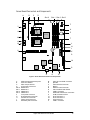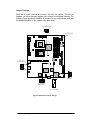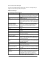
1
User Guide ® Great Minds Think C O M P U T E R S . N E T W O R K S . ® S O L U T I O N S Viglen, EMC and the 'CE' mark CE Marking As we begin the 21st century, European standards are being harmonised across borders. If products comply to the same standards in all European countries, product exporting and importing is made simple - paving our way to a common market. If you buy a product with a 'CE' mark on it (shown below), on the box, in the manual, or on the guarantee - it complies to the currently enforced directive(s). Introduction to EMC EMC (Electromagnetic Compatibility) is the term used to describe certain issues with RF (Radio Frequency) energy. Electrical items should be designed so they do not interfere with each other through RF emissions. E.g. If you turn on your microwave, your television shouldn't display interference if both items are CE marked to the EMC directive. If emitted RF energy is not kept low, it can interfere with other electrical circuitry - E.g. Cars Automatic Braking Systems have been known to activate by themselves while in a strong RF field. As this has obvious repercussions ALL electrical products likely to cause RF related problems have to be 'CE' marked from 1st January 1996 onwards. If a product conforms to the EMC directive, not only should its RF emissions be very low, but its immunity to RF energy (and other types) should be high. The apparatus has to resist many 'real world' phenomena such as static shocks and mains voltage transients. Viglen’s Environment laboratory To gain a 'CE' mark, the Viglen computer range has had to undergo many difficult tests to ensure it is Electromagnetically Compatible. These are carried out in the in-house 'Environment lab' at Viglen Headquarters. We have made every effort to guarantee that each computer leaving our factory complies fully to the correct standards. To ensure the computer system maintains compliance throughout its functional life, it is essential you follow these guidelines. Install the system according to Viglen’s instructions If you open up your Viglen Server: Keep internal cabling in place as supplied. Ensure the lid is tightly secured afterwards Do not remove drive bay shields unless installing a 'CE' marked peripheral in its place The clips or ‘bumps' around the lips of the case increase conductivity - do not remove or damage. Do not remove any ferrite rings from the L.E.D cables. Only use your Viglen computer with 'CE' marked peripherals This system has been tested in accordance with European standards for use in residential and light industrial areas-this specifies a 10 meter testing radius for emissions and immunity. If you do experience any adverse affects that you think might be related to your computer, try moving it at least 10 meters away from the affected item. If you still experience problems, contact Viglen’s Technical Support department who will put you straight through to an EMC engineer - s/he will do everything possible to help. If modifications are made to your Viglen computer system, it might breach EMC regulations. Viglen take no responsibility (with regards to EMC characteristics) of equipment that has been tampered with or modified. 1 Viglen SX120 Server User Guide - MA-SX120-0A-01 Copyrights and Trademarks Please note The material in this manual is subject to change without notice. Trademarks Microsoft, Windows, Windows NT, Windows 95, Windows 98, Windows 2000, MS-DOS and OS/2 are registered trademarks of Microsoft Corporation. i386, i486, Pentium, Pentium Pro and MMX are registered trademarks of Intel Corporation. JAC-UP, Contender, Dossier, Vig, Viglen, and Envy are trademarks of Viglen Limited. Genie and Contender are registered trademarks of Viglen Limited. Copyright and Patents This manual and all accompanying software and documentation are copyrighted and all rights reserved. This product, including software and documentation, may not, in whole or in part, be copied, photocopied, translated or reduced to any electronic or machine-readable form, without prior written consent except for copies retained by the purchaser for backup. © Copyright 2001 Viglen Limited All Rights Reserved Viglen SX120 Server - User Guide Version 1.1 Printed in the United Kingdom Liability No warranty or representation, either expressed or implied, is made with respect to this documentation, its quality, performance, merchantability or fitness for a particular purpose. As a result the documentation is licensed as is, and you, the licensee, are assuming the entire risk as to its quality and performance. The vendor reserves the right to revise this operation manual and all accompanying software and documentation and to make changes in the content without obligation to notify any person or organisation of the revision or change. In no event will the vendor be liable for direct, indirect, special, incidental or consequential damages arising out of the use or inability to use this product or documentation, even if advised of the possibility of such damages. In particular, the vendor shall not have liability for any hardware, software or data stored or used with the product, including the costs of repairing, replacing or recovering such hardware, software or data. Viglen SX120 Server User Guide 2 Contents Chapter 1: System Overview........................................................... 9 Introduction.................................................................................................9 System Components ................................................................................10 Server Board Features .............................................................................11 Server Board Connectors and Components ..........................................12 Controls, Connectors, and Indicators.....................................................13 Front Panel................................................................................................13 Control Panel Buttons .............................................................................13 Control Panel LED’s................................................................................14 Back Panel..............................................................................................15 Outline of Server Board Features ...........................................................16 Form Factor ............................................................................................16 ServerWorks ServerSet III LE Chipset ....................................................16 Microprocessor .......................................................................................16 Main memory ..........................................................................................17 OSB4/OSB5 IDE/USB South Bridge Controller ......................................17 On-Board SCSI .......................................................................................17 Onboard /IO ............................................................................................17 Integrated Network Interface...................................................................18 Expansion slots .......................................................................................18 Additional features ..................................................................................18 Processors ................................................................................................19 Microprocessor Packaging......................................................................19 Processor Upgrades ...............................................................................19 Memory......................................................................................................19 Main Memory ..........................................................................................19 SDRAM ...................................................................................................20 ECC Memory ..........................................................................................20 Chipset ......................................................................................................21 ATI Graphics Controller ...........................................................................21 Super I/O Controller..................................................................................21 Universal Serial Bus .................................................................................22 Floppy Controller......................................................................................23 IDE Support...............................................................................................23 Keyboard and Mouse Interface ...............................................................23 Real-time Clock, CMOS SRAM, and Battery...........................................24 Intel Pro/100+ Server (82559) Ethernet Controllers ...............................24 Wake on LAN ..........................................................................................24 3 Viglen SX120 Server User Guide - MA-SX120-0A-01 Chapter: 2 Removing and Installing Components........................... 26 Before You Begin......................................................................................26 Warnings and Cautions...........................................................................26 RACKMOUNT PRECAUSTIONS............................................................27 Tools and Supplies Needed .....................................................................28 Rackmounting...........................................................................................29 Identifying the Rackmount Rails..............................................................29 Fixing the Chassis Rails..........................................................................29 Installing the Server in the Rack .............................................................30 Removing the Server from the Rack .......................................................31 Gaining access to the Server Motherboard............................................32 Removing the Cover ...............................................................................32 Replacing the Cover................................................................................32 Overview of Jumper Settings ..................................................................32 Jumper Settings ......................................................................................33 Changing Jumper Settings ......................................................................34 Clearing the CMOS .................................................................................34 CPU Core/Bus Ratio Switch.....................................................................37 Motherboard Connectors.........................................................................37 Upgrading/ Installing the CPUs ...............................................................39 Removing the Processor.........................................................................39 Removing the Processor Chip ................................................................40 Installing the Processor...........................................................................41 Installing the Processor Heat Sink ..........................................................42 Upgrading/ Installing Memory .................................................................43 Removing the DIMM Boards ...................................................................43 Installing the DIMM Boards .....................................................................43 Upgrading/Installing the Hard Drive(s) ...................................................44 Hard Drive Specifications........................................................................44 Removing the Hard Drive(s)....................................................................45 Installing a PCI Add in Card.....................................................................47 Replacing the Clock/CMOS RAM Battery ...............................................48 Chapter 3: System BIOS .............................................................. 50 What is the BIOS?.....................................................................................50 The Power-on sequence .........................................................................50 Overview of BIOS Features......................................................................51 Introduction .............................................................................................51 How data is configured............................................................................51 BIOS Upgrades .......................................................................................51 BIOS Features ........................................................................................51 Plug and Play: PCI Auto-configuration ....................................................52 PCI IDE Support......................................................................................52 ISA Plug and Play ...................................................................................53 Viglen SX120 Server User Guide 4 Desktop Management Interface (DMI) ....................................................53 Language Support...................................................................................53 Boot Options ...........................................................................................53 OEM Logo or Scan Area .........................................................................54 BIOS Setup Access.................................................................................54 Configuring the BIOS ...............................................................................54 Before You Begin ....................................................................................54 BIOS Setup Program ..............................................................................55 Main Menu ..............................................................................................56 SuperIO Configuration Submenu ............................................................57 IDE Configuration Submenu ...................................................................57 Settings for the IDE Channel...................................................................59 Floppy Configuration Submenu...............................................................60 Boot Settings Configuration Submenu ....................................................61 Event Log Configuration Submenu .........................................................63 Peripheral Device Configuration Submenu .............................................63 System Health Monitor Configuration Submenu .....................................64 Chipset Setup Menu................................................................................64 PCI PnP Setup ........................................................................................66 Power Setup ...........................................................................................68 Boot Setup ..............................................................................................69 Security Setup.........................................................................................70 Exit Setup................................................................................................71 Upgrading / Recovering the BIOS ...........................................................71 Preparing for the Upgrade.......................................................................71 Chapter 4: Solving Problems........................................................ 74 Resetting the System ...............................................................................74 Troubleshooting Procedure.....................................................................75 Problems and Suggestions .....................................................................76 Error and Information Messages.............................................................79 BIOS Error Messages .............................................................................79 BIOS Beep Codes .....................................................................................80 BIOS Post Checkpoint Codes..................................................................81 B-1 Uncompressed Initialisation Codes ..................................................81 B-2 Bootblock Recovery Codes ..............................................................82 B-3 Uncompressed Initialisation Codes ..................................................83 B-4 Bus Checkpoint Codes .....................................................................88 Additional Bus Checkpoints ....................................................................88 Chapter 5: Technical Information.................................................. 89 SCSI Controller .........................................................................................89 IDE Controller ...........................................................................................89 Operating Systems and IDE hard drives ................................................90 Network Controllers .................................................................................91 5 Viglen SX120 Server User Guide - MA-SX120-0A-01 Environmental Specifications .................................................................92 Use Only for Intended Applications ........................................................92 Equipment Log and Worksheets .............................................................93 Worksheet, Calculating DC Power Usage ..............................................95 Connector Pin Signal Details...................................................................95 Fan Connector ........................................................................................95 Keyboard and Mouse ..............................................................................95 Serial Ports COM1 and COM2 ................................................................96 Parallel Port ............................................................................................96 Floppy Drive ............................................................................................97 Integrate Device Interface (IDE)..............................................................98 ATX Power Supply ..................................................................................98 Universal Serial Bus (USB) .....................................................................99 50-pin Legacy SCSI Connector...............................................................99 Ultra 160 SCSI Connector.....................................................................100 Peripheral Component Interconnect (PCI) ............................................101 Other Information ...................................................................................102 Reliability...............................................................................................102 Figures Figure 1: Location of the major system components in the Viglen SX120 Server.............................................................................................................10 Figure 2: Server Board Connectors and Components ...................................12 Figure 3: Front Panel of the SX120 Server ....................................................13 Figure 4: SX120 Server Back Panel...............................................................15 Figure 5: I/O Ports ..........................................................................................16 Figure 6: Identifying the Sections of the Rack Rails .......................................29 Figure 7: Fixing Chassis Rails .......................................................................30 Figure 8: Installing the server in the rack........................................................31 Figure 9: Motherboard Jumper Settings .........................................................33 Figure 10.1: CMOS Clear Jumper..................................................................34 Figure 10.2: CMOS Clear Jumper..................................................................35 Figure 10.3: CMOS Clear Jumper..................................................................35 Figure 11: JF1 Front Panel Connector ...........................................................38 Figure 12: Removing the Processor Heat Sink ..............................................40 Figure 13: Installing the Processor Chip.........................................................41 Figure 14: Installing the Processor Heat Sink ................................................42 Figure 15: Removing the DIMM Modules .......................................................43 Figure 16: Hard Drive Carrier .........................................................................45 Figure 17: Attaching A SCSI Drive to the Hard Disk Carrier...........................46 Figure 18: Installing the Hard Drive Carrier in the SX120...............................47 Figure 19: Location of PCI Riser Card Retention Rail ....................................48 Figure 20: Installing a new Battery .................................................................49 Figure 21: Main BIOS Setup Screen ..............................................................56 Tables Viglen SX120 Server User Guide 6 Table 1: List and brief description of the Viglen SX120 Server’s key features .9 Table 2: Summary of Server Board Features.................................................11 Table 3: DIMM Sizes accepted by the SX120 Server ....................................20 Table 4: Clearing the system CMOS ..............................................................36 Table 5: Setting the Front Side Bus Speed ....................................................36 Table 6: Enabling or Disabling SCSI Termination on the Ultra160 Channel...36 Table 7: Enabling or Disabling the Onboard LAN/NIC ...................................36 Table 8: Onboard VGA Enabled/Disabled......................................................36 Table 9: CPU Switch Settings ........................................................................37 Table 10: ATAPI Device Configuration Recommendations ............................53 Table 11: BIOS Function Keys .......................................................................55 Table 12: Main BIOS Section Options............................................................56 Table 14: SuperIO Configuration Submenu ...................................................57 Table 15: IDE Configuration Submenu...........................................................58 Table 16: IDE Channel Settings .....................................................................59 Table 17: Floppy Configuration Submenu ......................................................60 Table 18: Boot Settings Configuration Submenu ...........................................61 Table 19: Event Log Configuration Submenu.................................................63 Table 20: Peripheral Device Configuration Submenu ....................................63 Table 21: System Health Monitor Configuration Submenu ............................64 Table 22: Chipset Setup Menu.......................................................................64 Table 23: PCI PnP Setup ...............................................................................66 Table 24: Power Setup...................................................................................68 Table 25: Boot Setup .....................................................................................69 Table 26: Security Setup ................................................................................70 Table 27: Exit Setup .......................................................................................71 Table 28: Resetting the System .....................................................................74 Table 29: General FAQs ................................................................................76 Table 29: continued........................................................................................77 Table 29: continued........................................................................................78 Table 30: Explanation of BIOS Error Messages.............................................79 Table 31: BIOS Beep Codes ..........................................................................80 Table 32: BIOS B-1 Uncompressed Initialisation Codes ................................81 Table 33: B-2 Bootblock Recovery Codes......................................................82 Table 34: B-3 Uncompressed Initialisation Codes..........................................83 Table 35: B-4 Bus Checkpoint Codes ............................................................88 Table 36: High Byte Checkpoints for Bits 7-4.................................................88 Table 37: High Byte Checkpoints for Bits 3-0.................................................88 Table 38: Environmental Specifications of the SX120 Server ........................92 Table 39: Equipment Log ...............................................................................93 Table 40: Worksheet for Calculating DC Power Usage..................................95 Table 41: Fan Connector Pin-out (Thermal, CPU and Chassis Fans .............95 Table 42: PS/2 Keyboard/Mouse Connectors ................................................96 Table 43: Serial Port Connectors ...................................................................96 Table 44: Parallel Port Connector ..................................................................96 Table 45: Floppy Drive Connector Pin-out .....................................................97 Table 46: IDE Connectors ..............................................................................98 Table 47: Main Power Supply Connector .......................................................98 Table 48: USB Connector Pin-out ..................................................................99 7 Viglen SX120 Server User Guide - MA-SX120-0A-01 Table 49: 50-pin SCSI Pin-out........................................................................99 Table 50: Ultra160 SCSI Pin-out ..................................................................100 Table 51: 66MHz, 64-bit PCI Connectors.....................................................101 Viglen SX120 Server User Guide 8 Chapter 1: System Overview Introduction This manual describes the chassis and system level features of the Viglen SX120 Server. This system is a high-density rackmount server consisting of a 1U chassis and a dual 370-pin Pentium III server board. Table 1: List and brief description of the Viglen SX120 Server’s key features Features Description 1U Chassis Weight Power Supply Cooling Rackmounting 44mm (height) x 425mm (width) x 580mm (depth) 11.8 kg when fully loaded Single 250W power supply (Auto-switching 110/225V) One 10cm Blower Two sliding rails, Four Brackets and screws to attach rails to chassis and brackets (Cage nuts not included) Two Hot-swap hard drive bays, supporting two 1” U160 SCSI SCA hard drives. Single standard 3.5” diskette drive and slim-line CD-ROM drive Hard disk bay Other External Drive Bay Microprocessor Memory Capacity LAN Support SCSI Support Add-in card support BIOS 9 Dual Pentium III processors in FCPGA 370-pin socket Up to 4GB of ECC Registered PC-100/133 SDRAM DIMMs Integrated dual Intel Pro/100+ Server (82559) Ethernet controllers Adaptec AIC-7892 Ultra160 SCSI controller One PCI riser (64-bit/33MHz) supports a full-length PCI card. AMI BIOS Viglen SX120 Server User Guide - MA-SX120-0A-01 System Components Figure 1: Location of the major system components in the Viglen SX120 Server Viglen SX120 Server User Guide 10 Server Board Features Table 2: Summary of Server Board Features Feature Description Form Factor Processor Full ATX (11.475 inches by 12.05 inches) Supports two Intel® Pentium® III processors in an FCPGA 370-pin socket. • Four 168-pin dual in-line memory module (DIMM) sockets • Supports ECC Registered SDRAM DIMMs • Supports up to 4 GB of ECC SDRAM ServerWorks ServerSet III LE, consisting of • A CNB20ELE-SL Host (North) Bridge • A OSB4 South Bridge • Onboard ATI Rage XL 8MB PCI • 32 bit Graphics memory bus • Two integrated Intel® Pro/100+ Server (82559) Ethernet controllers • Integrated Adaptec AIC-7892 Ultra160 SCSI controller • One standard diskette drive interface • Two IDE interfaces with Ultra DMA/33 support • One fast UART 16550A compatible serial ports • Two USB ports • Two PS/2 interfaces for keyboard and mouse • LED panel interface One PCI bus in with a single-slot PCI riser card (64 bit/33 MHz) • AMI 4 MB BIOS • ACPI/APM power management Plug and Play • BIOS rescue recovery feature • Hardware BIOS virus protection • Speaker • Wake on LAN • SCSI LED connector Memory Chipset Graphics Controller Peripheral Interfaces Expansion BIOS Other Features 11 Viglen SX120 Server User Guide - MA-SX120-0A-01 Server Board Connectors and Components A B C D Slot 0 Slot 1 Slot 2 Slot 3 F Y H PGA 370 Socket X P North Bridge W T V1 V2 U PGA 370 Socket L N J K NIC G NIC ATI M Adapt ec SCSI South Bridge Syst em BIO S Super I/O G S R Q Figure 2: Server Board Connectors and Components A B C D Slot 0 Slot 1 Slot 2 Slot 3 F G H J K PS/2 keyboard and Mouse ports CPU Fan Headers PGA 370-pin Sockets ATX Power Connectors DIMM slot 0 DIMM slot 1 DIMM slot 2 DIMM slot 3 Front panel Connector Overheat Alarm Connector Chassis Fan Connector Floppy Drive Connector Secondary IDE Connector M N P P Q R S T U V1 V2 W X Ultra 160 LVD SCSI Connector Speaker Ultra160 SCSI Connector Battery Wake On LAN Connector CPU Core/Bus Ratio Switch COM 2 Connector Additional Chassis Fan connectors 64-Bit, 33 MHz PCI Slot RJ-45 Connector 1 RJ-45 Connector 2 VGA Connector COM 1 Connector Viglen SX120 Server User Guide 12 Controls, Connectors, and Indicators Front Panel Figure 3: Front Panel of the SX120 Server Control Panel Buttons There are two push-button buttons located on the front of the chassis. These are (in order from left to right) a reset button and a power on/off button. RESET: The reset switch reboots the system. POWER: This is the main power switch, which is used to apply or turn off the main system power. Turning off system power with this button removes the main power but keeps standby power supplied to the system. 13 Viglen SX120 Server User Guide - MA-SX120-0A-01 Control Panel LED’s The control panel provides important system monitoring and control information. LED’s indicate power on, network activity; hard disk drive activity and system overheat conditions. The control panel also includes a main power button and a system reset button. This section explains what each LED indicates when illuminated and any corrective action you may need to take. Overheat: Indicates an overheat condition in the chassis. This may be caused by cables obstructing the airflow in the system, or the ambient room temperature being too warm. You should also check to make sure that the chassis cover is installed and that all fans are present and operating normally. Finally, check the air seals for damage. The air seals are located under the blower fan and beneath the frame cross section that separates the drive bay area from the motherboard area of the chassis. NIC1: Indicates network activity on LAN1 when flashing. NIC2: Indicates network activity on LAN2 when flashing. HDD: Indicates IDE channel activity. On the SX120 Server, this light indicates CD-ROM drive activity when flashing. Power: Indicates power is being supplied to the system's power supply units. This LED should normally be illuminated when the system is operating. Viglen SX120 Server User Guide 14 Each SCSI drive carrier has two LED’s: Green: When illuminated, the green LED on the front of the SCSI drive carrier indicates drive activity. A connection to the SCSI SCA backplane enables this LED to blink on and off when that particular drive is being accessed. Red: A SAF-TE compliant backplane is needed to activate the red LED to indicate a drive failure. If one of the SCSI drives fail, you should be notified by your system management software. Back Panel The input/output connectors are accessible at the back panel of the chassis as shown in Figure 4 and 5. Figure 4: SX120 Server Back Panel NOTE: The mouse and keyboard can’t be plugged into either of the PS/2 connectors. Power to the computer should be turned off before a keyboard or mouse is connected or disconnected. 15 Viglen SX120 Server User Guide - MA-SX120-0A-01 I/O Ports The I/O ports are colour coded in conformance with the PC 99 specification. Figure 5: I/O Ports NOTE: The COM2 Port is a header on the motherboard, located near the Ultra160 SCSI channel B connector (JA3). Outline of Server Board Features The SX120 server board supports single or dual FCPGA (Flip Chip Pin Grid Array) Pentium III processors running between 500MHz to 1.26+GHz with 256Kb or 512Kb of integrated L2 cache, running at 100 MHz or 133MHz Bus speed. Form Factor • ATX form factor of 11.475 x 12.05 inches ServerWorks ServerSet III LE Chipset • 100 and 133MHz processor host bus interface support, dependent on Processor Front Side Bus • Single 64-Bit 33MHz PCI • Support for 4GB of Registered ECC SDRAM Microprocessor • Single or dual Pentium III processor using socket 370 connectors • 100 and 133 MHz Front Side Bus speed • 256 or 512Kb second-level Advanced Transfer cache on the substrate Viglen SX120 Server User Guide 16 Main memory • Four 168-pin DIMM sockets for ECC 3.3V memory only • Support for up to 4GB of 100 or 133MHz registered ECC SDRAM DIMMS NOTE: • The memory speed must match the front side bus speed being used. (Both 133 or 100 MHz.) • The DIMM slots on the SX120 motherboard are set at a 25° angle to provide a low vertical profile. • Memory Modules should be installed first in DIMM slot 0, then DIMM slot 1, then DIMM slot 2 and finally DIMM slot 3. OSB4/OSB5 IDE/USB South Bridge Controller • Supports up to four IDE drives or devices • Two USB Ports • UDMA-33, transfer rates up to 33MB/sec • 4MB BIOS Flash ROM • Security (passwords and system protection) On-Board SCSI • Adaptec AIC-7892 controller Interface • Dual Ultra160 LVD (Low Voltage Differential) SCSI Interface • Up to 15 devices per channel (depending on configuration) • 160MB/sec max data transfer rate on the Ultra160 channel Onboard /IO • Integrated ATI Rage XL Graphics Controller • 2 EIDE bus master interfaces support Ultra DMA/33 • 1 floppy port interface (up to 2.88 MB) • 1 Fast UART 16550A compatible serial ports • PS/2 mouse and PS/2 keyboard ports 17 Viglen SX120 Server User Guide - MA-SX120-0A-01 • 2 USB (Universal Serial Bus) ports Integrated Network Interface • Intel 82559 100 Pro+ Server adapters • For 10 or 100 Mbps TX fast Ethernet networks Expansion slots • Single 64 bit 33MHz PCI Slot Additional features • 4MB AMI Flash BIOS • APM 1.2, DMI 2.1, PCI 2.2, ACPI 1.0, Plug and Play (PnP) • Wake-on-LAN (WOL) Viglen SX120 Server User Guide 18 Processors The motherboard has two 370-pin sockets, which support Intel Pentium III FCPGA processors. The processor’s VID pins automatically program the voltage regulator on the motherboard to the required processor voltage. The motherboard currently supports processors that run internally at 500MHz to a maximum of 1.26+GHz with 133 or 100 MHz front side bus and 256KB-512KB second-level cache. Microprocessor Packaging The Intel Pentium III processor for the FCPGA socket is the next member of the P6 family, in the Intel IA-32 processor line. This package utilises the same 370-pin zero insertion force socket (PGA370) used by the Intel Celeron range of processors. The auto-switching voltage regulator for the CPU core can support up to 20A current and auto-sense voltage IDs ranging from 1.4V to 3.5V. This will allow the regulator to run cooler and thus make the system more stable. When the Pentium III processors are mounted into the 370-pin socket connectors, they are secured by a leaver attached to the motherboard. Processor Upgrades The motherboard can be upgraded with Pentium III processors that run at higher speeds. When upgrading the processor the USER must manually configure the processor speeds using the DIP Switch (SW1) on the motherboard, see Figure 2 and Table 5 for settings. Viglen recommend using identical stepping processors with the SX120 server board whenever possible. Memory Main Memory The motherboard has four dual inline memory module (DIMM) sockets. The minimum memory size is 64MB and the maximum memory size is 4GB. The BIOS automatically detects memory type, size, and speed. • The motherboard only supports the following memory features: • 168-pin DIMMS with gold-plated contacts. • 100/133MHz (PC-100 & PC-133) SDRAM only. • ECC (72-bit) 3.3V memory only. 19 Viglen SX120 Server User Guide - MA-SX120-0A-01 • Registered memory only • Single or double-banked DIMMs in the following sizes: Table 3: DIMM Sizes accepted by the SX120 Server DIMM Size 64 MB 128 MB ECC Configuration 8 Mbit x 72 16 Mbit x 72 Unbuffered/Registered Registered Only Registered Only 256 MB 32 Mbit x 72 Registered Only 512 MB 64 Mbit x 72 Registered Only 1 GB 128 Mbit x 72 Registered Only NOTE: • The memory speed must match the front side bus speed being used. (Either 133 or 100 MHz.) • The DIMM slots on the SX120 motherboard are set at a 25° angle to provide a low vertical profile. • Memory Modules should be installed first in DIMM slot 0, then DIMM slot 1, then DIMM slot 2 and finally DIMM slot 3. SDRAM Synchronous DRAM (SDRAM) improves memory performance through memory access that is synchronous with the memory clock. This simplifies the timing design and increases memory speed because all timing is dependent on the number of memory clock cycles. ECC Memory Error checking and correcting (ECC) memory detects multiple-bit errors and corrects single-bit errors. Viglen SX120 Server User Guide 20 Chipset The ServerWorks ServerSet™ III LE is a high-performance core logic chipset that consists of a North Bridge and a South Bridge. The North Bridge integrates the main memory subsystem and a dual channel PCI bus and bridges the processor bus to a 64-bit PCI bus. The memory subsystem consists of a two-way interleaved 4-DIMM configuration accessed over a 144-bit memory bus (most chipsets have a 72-bit memory bus), which provides a significant boost in performance. The North Bridge also packs and unpacks data for PCI accesses to reserve more processor bandwidth for multiprocessor motherboards. The South Bridge provides various integrated functions, including the PCI to ISA Bridge and support for UDMA33, security (passwords and system protection), Plug & Play, USB, power management, interrupt controllers and the SMBus. ATI Graphics Controller The SX120 Server Board has an integrated ATI video controller based on the Rage XL graphics chip. The Rage XL fully supports sideband addressing and AGP texturing. This onboard graphics package can provide a bandwidth of up to 512 MB/sec over a 32-bit graphics memory bus. Super I/O Controller The disk drive adapter functions of the Super I/O chip include a floppy disk drive controller that is compatible with industry standard 82077/765, a data separator, write pre-compensation circuitry, decode logic, data rate selection, a clock generator, drive interface control logic and interrupt and DMA logic. The wide range of functions integrated onto the Super I/O greatly reduces the number of components required for interfacing with floppy disk drives. The Super I/O supports 360 K, 720 K, 1.2 M, 1.44 M or 2.88 M disk drives and data transfer rates of 250 Kb/s, 500 Kb/s or 1 Mb/s. It also supports two highspeed, 16550 compatible serial communication ports (UARTs), one of which supports serial infrared communication. Each UART includes a 16-byte send/receive FIFO, a programmable baud rate generator, complete modem control capability and a processor interrupt system. Each UART includes a 16-byte send/receive FIFO, a programmable baud rate generator, complete modem control capability and a processor interrupt system. Both UARTs provide legacy speed with baud rate of up to 115.2 Kbps as well as an advanced speed with baud rates of 250 K, 500 K, or 1 Mb/s, which support higher speed modems. 21 Viglen SX120 Server User Guide - MA-SX120-0A-01 The Super I/O provides functions that comply with ACPI (Advanced Configuration and Power Interface), which includes support of legacy and ACPI power management through an SMI or SCI function pin. It also features auto power management to reduce power consumption. The IRQs, DMAs and I/O space resources of the Super I/O can flexibly adjust to meet ISA PnP requirements, which support ACPI and APM (Advanced Power Management). Universal Serial Bus The server board has two universal serial bus (USB) ports that accommodate one USB peripheral connected to each port. For more than two USB devices, an external hub can be connected to either port. The two USB ports are implemented with stacked back panel I/O connectors. The server board fully supports UHCI and uses UHCI-compatible software drivers. USB has the following capabilities: • Self identification of peripherals which can be plugged in while the computer is running. • Automatic mapping of function to driver and configuration. • Support for synchronous and asynchronous transfer types over the same set of wires. • Guaranteed bandwidth and low latencies appropriate for telephony, audio, and other applications. • Error-handling and fault-recovery mechanisms built into the protocol. NOTE: Computer systems that have an unshielded cable attached to a USB port may not meet CE requirements; even if no device or a low-speed USB device is attached to the cable. Use shielded cable that meets the requirements for full-speed devices Viglen SX120 Server User Guide 22 Floppy Controller In the Setup program, the floppy interface can be configured for the following floppy drive capacities and sizes: • • • • • 360 KB, 5.25-inch 1.2 MB, 5.25-inch 720 KB, 3.5-inch 1.44 MB, 3.5-inch 2.88MB, 3.5-inch IDE Support The motherboard has two independent bus-mastering PCI IDE interfaces. These interfaces support PIO Mode 3, PIO Mode 4, ATAPI devices (e.g. CDROM), and DMA mode transfers. The BIOS supports logical block addressing (LBA) and cylinder head sector (CHS) translation modes. The BIOS automatically detects the IDE device transfer rate and translation mode. Programmed I/O operations usually require a substantial amount of processor bandwidth. However, in multitasking operating systems, the bandwidth freed by bus mastering IDE can be devoted to other tasks while disk transfers are occurring. Keyboard and Mouse Interface PS/2 keyboard and mouse connectors are located on the back panel. The 5V lines to these connectors are protected with a PolySwitch circuit that, like a self-healing fuse, re-establishes the connection after an over-current condition is removed. The keyboard controller contains the AMI Megakey keyboard and mouse controller code, which provides the keyboard and mouse control functions, and supports password protection for power on/reset. A power on/reset password can be specified in Setup. The keyboard controller also supports the hot-key sequence <Ctrl><Alt><Del> for a software reset. This key sequence resets the computer’s software by jumping to the beginning of the BIOS code and running the Power-On Self Test (POST). 23 Viglen SX120 Server User Guide - MA-SX120-0A-01 Real-time Clock, CMOS SRAM, and Battery The clock provides a time-of-day clock and a multi-century calendar with alarm features and century rollover. The time, date, and CMOS values can be specified in the Setup program. The CMOS values can be returned to their defaults by using the Setup program. An external coin-cell battery powers the real-time clock and CMOS memory. When the computer is not plugged into a wall socket, the battery has an estimated life of three years. When the computer is plugged in, the 3.3-V standby current from the power supply extends the life of the battery. The clock is accurate to ± 13 minutes/year at 25 ºC with 3.3V applied. Intel Pro/100+ Server (82559) Ethernet Controllers Two Intel Pro/100+ Server (82559) Ethernet controllers provide two 10/100 Base-T interfaces accessible from the back. The LAN connectors on the back panel provide LED’s to indicate transmit/receive activity and speed. Wake on LAN features are supported by the SX120 server board. See the BIOS specification for information regarding Alert on LAN and Wake on LAN. Also see “Wake on LAN” for more information. CAUTION For Wake on LAN, the 5V standby line for the power supply must be capable of delivering +5V ±5% at 720mA. Failure to provide adequate standby current, when implementing Wake on LAN can damage the power supply. Wake on LAN Wake-On-LAN is defined as the ability of a management application to remotely power up a computer that is powered off. Remote PC setup, updates and asset tracking can occur after hours and on weekends so that daily LAN traffic is kept to a minimum and users are not interrupted. The SX120 server motherboard has a 3-pin header (WOL) to connect to the 3-pin header on a Network Interface Card (NIC) that has WOL capability. Wake-On-LAN must be enabled in BIOS. Note that Wake-On-LAN can only be used with an ATX 2.01 (or above) compliant power supply. See Figure 2, page 12 “Server Board Connectors and Components” for the location of the Wake on LAN connector. Viglen SX120 Server User Guide 24 System Airflow Airflow is provided by a 10-cm input fan cooling fan. The system component layout was carefully designed to promote sufficient airflow through the small 1U rackmount space. Also note that all power and data cables have been routed in such a way that they do not block the airflow generated by the fans. The blower fan runs at a full 100% rpm. If the fan fails, the ambient air temperature in the chassis will rise and activate the overheat LED on the control panel. 25 Viglen SX120 Server User Guide - MA-SX120-0A-01 Chapter: 2 Removing and Installing Components This chapter provides procedures for removing and installing replaceable and/or upgradeable components in the Viglen SX120 Server. Before performing the procedures, be sure to familiarise yourself with the following “Before You Begin” information. Before You Begin Warnings and Cautions Read and adhere to all warnings, cautions, and notes in this guide and the documentation referenced and supplied with the server. If the additional instructions supplied with the server are inconsistent with these instructions, contact the supplier to find out how you can ensure that your server meets safety and regulatory requirements. WARNINGS This chapter is intended for qualified technical personnel with experience installing and configuring servers. SYSTEM POWER ON/OFF: The Power button on the server front panel DOES NOT remove AC power to the server system. Some circuitry in the server may continue to operate even though the front panel Power button is off. Always disconnect the power cord from the AC power source or wall outlet before performing any of the procedures in this guide. Failure to do so can result in personal injury or equipment damage. HAZARDOUS CONDITIONS, POWER SUPPLY: Hazardous voltage, current, and energy levels are present inside the power supply. There are no user-serviceable parts inside the power supply; servicing should be done by technically qualified personnel. HAZARDOUS CONDITIONS, DEVICES, & CABLES: Hazardous electrical conditions may be present on power, telephone, and communication cables. Press the Power button to turn off the server and disconnect the power cord from the AC power source, telecommunications systems, networks, and modems attached to the server before removing the cover. Otherwise, personal injury or equipment damage can result. CAUTION ELECTROSTATIC DISCHARGE (ESD) AND ESD PROTECTION: Perform the procedures in this chapter only at an electrostatic discharge (ESD) workstation since the server components can be extremely sensitive to ESD. If no such station is available, you can reduce the risk of electrostatic discharge ESD damage by doing the following: Viglen SX120 Server User Guide 26 • • • • • • • • Wear an antistatic wrist strap and attach it to a metal part of the server. Touch the metal on the server chassis before touching the server components. Keep part of your body in contact with the metal server chassis to dissipate the static charge while handling the components. Avoid moving around unnecessarily. Hold the server components (especially boards) only by the edges. Place the server components on a grounded, static-free surface. Use a conductive foam pad if available but not the component wrapper. Do not slide the components over any surface. COOLING AND AIRFLOW: For proper cooling and airflow, always install the chassis access cover before turning on the system. Operating the system without the cover in place can cause overheating and damage to system parts. RACKMOUNT PRECAUSTIONS Familiarise yourself with the following precautions before rackmounting the server. WARNINGS ANCHOR THE EQUIPMENT RACK: The equipment rack must be anchored to an unmovable support to prevent it from falling over when one or more devices are extended in front of it on slide assemblies. The anchors must be able to withstand a force of up to 113 kg (250 lbs.). You must also consider the weight of any other device installed in the rack. MAIN AC POWER DISCONNECT: You are responsible for installing an AC power disconnect for the entire rack unit. This main disconnect must be readily accessible, and it must be labelled as controlling power to the entire unit, not just to the server(s). GROUNDING THE RACK INSTALLATION: To avoid the potential for electrical shock, you must include a third wire safety-grounding conductor with the rack installation. If server power cords are plugged into AC outlets that are part of the rack, then you must provide proper grounding for the rack itself. If server power cords are plugged into wall AC outlets, the safety-grounding conductor in each power cord provides proper grounding only for the server. You must provide additional, grounding for the rack and other devices installed in it. 27 Viglen SX120 Server User Guide - MA-SX120-0A-01 OVERCURRENT PROTECTION: The server is designed for an AC line voltage source with up to 20 amperes of over current protection. If the power system for the equipment rack is installed on a branch circuit with more than 20 amperes of protection, you must provide supplemental protection for the server. If more than one server is installed in the rack, the power source for each server must be from a separate branch circuit. CAUTION TEMPERATURE: The operating temperature of the server, when installed in an equipment rack, must not go below 5°C (41°F) or rise above 35°C (95°F). Extreme fluctuations in temperature can cause a variety of server problems. VENTILATION: The equipment rack must provide sufficient airflow to the front of the server to maintain proper cooling. There must be sufficient ventilation to exhaust at least 1,500 BTU per hour for each server. The rack selected and the ventilation provided must be suitable to the environment in which the server will be used. Tools and Supplies Needed 1. 2. 3. 4. 5. Phillips (cross-head) screwdriver (number 1 and 2 bit) Flat-head screwdriver (3/16-inch) Jumper removal tool or needle nosed pliers Pen or pencil Antistatic wrist strap and conductive foam pad (recommended) Viglen SX120 Server User Guide 28 Rackmounting Identifying the Rackmount Rails You should have received two rack rail assemblies with the SX120 Server. Each of these assemblies consists of two sections: an inner fixed chassis rail that secures to the server (A) and an outer fixed rack rail that secures directly to the rack itself (B). A sliding rail guide sandwiched between the two should remain attached to the fixed rack rail. (See below Figure 6). The A and B rails must be detached from each other to install. To remove the fixed chassis rail (A), pull it out as far as possible - you should hear a "click" sound as a locking tab emerges from inside the rail assembly and locks the inner rail. Then depress the locking tab to pull the inner rail completely out. Do this for both the left and right side rack rail assemblies. Figure 6: Identifying the Sections of the Rack Rails Fixing the Chassis Rails Position the fixed chassis rail sections you just removed along the side of the SX120 chassis making sure the five screw holes line up. Note that these two rails are left/right specific. Screw the rail securely to the side of the chassis (see Figure 7 on the next page). Repeat this procedure for the other rail on the other side of the chassis. Both chassis rails have a locking tab, which serves two functions. The first is to lock the server into place when installed and pushed fully into the rack, which is its normal position. Secondly, these tabs also lock the server in place when fully extended from the rack. This prevents the server from coming completely out of the rack when you pull it out for servicing. 29 Viglen SX120 Server User Guide - MA-SX120-0A-01 Figure 7: Fixing Chassis Rails Installing the Server in the Rack This procedure describes how to install the server in the rack. Before proceeding, be sure and familiarise yourself with the “Rackmount Precautions” information in the “Before You Begin” section at the front of this chapter. Refer to Figure 8 on the next page while performing this procedure. 1. Orient the server with the rackmount brackets aligned with the desired mounting holes in the rack posts. 2. Use a Phillips screwdriver and start to place the screws removed in the previous “Removing the Server from the Rack” procedure and loosely attach the mounting brackets (one on each side of the server) to the rack posts. Do not tighten. 3. Properly align the server in the rack. 4. Use a Phillips screwdriver and tighten the screws to securely attach the mounting brackets to the rack posts. You should now have rails attached to both the chassis and the rack unit. The next step is to install the server into the chassis. Do this by lining up the rear of the chassis rails with the front of the rack rails. Slide the chassis rails into the rack rails, keeping the pressure even on both sides (you may have to depress the locking tabs when inserting). When the server has been pushed completely into the rack, you should hear the locking tabs "click". Viglen SX120 Server User Guide 30 Figure 8: Installing the server in the rack Removing the Server from the Rack This procedure describes how to remove the server from the rack. Before proceeding, be sure you are thoroughly familiar with the information in “Before You Begin” at the front of this chapter. 1. Use a Phillips screwdriver to remove the screws that secure the server mounting brackets to the rack posts 2. Grasp the two handles on either side of the server and pull the unit straight out until it locks (you will hear a “click”). 3. Carefully remove the server from the front of the rack. 31 Viglen SX120 Server User Guide - MA-SX120-0A-01 Gaining access to the Server Motherboard Removing the Cover This procedure describes how to remove the cover from the server. Before proceeding, be sure you are thoroughly familiar with the information in “Before You Begin” at the front of this chapter. 1. Press down on the two release buttons near the front bezel, simultaneously pull the cover back until it slides out from under the edge of the server front panel. 2. Grasp the front of the cover and lift to remove it from the server. Replacing the Cover This procedure describes how to replace the cover on the server. Before proceeding, be sure you are thoroughly familiar with the information in “Before You Begin” at the front of this chapter. 1. Position the cover on the chassis with the edge containing the buttons facing the front and the sides of the cover outside the chassis frame. 2. Grasp the back edge of the cover and simultaneously push from the back and top until the front edge of the cover slides all the way under the edge of the server front panel. Overview of Jumper Settings The system motherboard inside your computer contains headers and jumpers. Different pin and jumper configurations make it possible to change how the computer functions. This section of the manual should give you all the information you will require making any changes. Changes you can make, in this way, are as follows: • • • • Reset the CMOS RAM settings to the default values. Setting the Front Side Bus Speed Enabling or disabling SCSI termination Enabling or disabling the onboard Network Connector CAUTION Never remove jumpers using large pliers as this can damage the pins. The best way to remove a jumper is to use a small pair of tweezers or fine needle-nosed pliers. Never remove a jumper when the computer is switched on. Always switch the computer off first. Viglen SX120 Server User Guide 32 Jumper Settings Each set of 3 pins requires one jumper, and has two options. The two pin headers can allow changes between two options for individual features. The following figure shows the position of jumpers on the motherboard, and also the standard position of the jumpers (two white pins). JP2 Front Side Bus Speed JF1 Front Panel Header PGA 370 Socket North Bridge PGA 370 Socket JP8 & JP24 LAN Enable/Disable NIC NIC South Bridge ATI Syst em BIO S Adapt ec SCSI Super I/O JBT1 CMOS Clear JP1 SCSI Termination Enable/Disable SW1 CPU Core/ Bus Ratio Figure 9: Motherboard Jumper Settings 33 Viglen SX120 Server User Guide - MA-SX120-0A-01 CAUTION Do not move the jumper with the power on. Always turn off the power and unplug the power cord from the computer before changing the jumper. Changing Jumper Settings Before commencing any work inside your Viglen system please read the warnings and cautions at the beginning of this Chapter. Below is an example of a list of actions to take to change the jumper setting for the Clear CMOS option. Most of the actions below refer to all of the jumpers that you might wish to change. Any differences for the changing of each jumper are listed in a table. Clearing the CMOS NOTE: Clearing the CMOS will load the Manufacture default settings in to the NVRAM. Figure 9 shows the location of the CMOS clear header on the motherboard. The jumper is usually set to pins 1-2 (Preserve contents of CMOS). CMOS Clear Jumper JBT1 (1-3) Figure 10.1: CMOS Clear Jumper NOTE: A jumper is a small plastic conductor that slips over two header pins. To change a setting, remove the jumper from the pins and slide it onto the new pins for the desired setting. CAUTION To avoid bending or breaking pins, use caution when removing or installing a jumper. This procedure assumes that the motherboard is installed in the computer and the configuration header (JBT1) has the jumper set to the defaults. 1. Observe the precautions in “Before You Begin”. 2. Turn off all peripheral devices connected to the computer. Turn off the computer. 3. Remove the computer cover. Viglen SX120 Server User Guide 34 4. Locate the Jumper header. 5. On the header (JBT1), move the first jumper to pins 2-3 as shown below to set the clear CMOS mode. CMOS Clear Jumper JBT1 (1-3) Figure 10.2: CMOS Clear Jumper 6. Replace the cover, turn on the computer, and allow it to boot. 7. Turn off the computer. 8. Remove the computer cover. 9. On the header (JBT1), move the first jumper back to pins 1-2 to restore normal operation as shown below. CMOS Clear Jumper JBT1 (1-3) Figure 10.3: CMOS Clear Jumper 10. Replace the cover and turn on the computer. 35 Viglen SX120 Server User Guide - MA-SX120-0A-01 The following eight tables show the various jumper settings, which can be altered within your system. Table 4: Clearing the system CMOS Jumper JBT1 1-2 2-3 Configuration Preserve contents of NVRAM. Replace contents of NVRAM with default settings. Table 5: Setting the Front Side Bus Speed CPU speed = FSB x Core/Bus ratio Jumper JP2 Configuration 1-2 Auto 2-3 100 MHz OFF 133 MHz NOTE • • The Auto setting allows the CPU to set the speed. Jumpers JP2 has to be altered in order to set the Front Side Bus Speed, without it, you may encounter problems when booting the server. Table 6: Enabling or Disabling SCSI Termination on the Ultra160 Channel Jumper JP1 Open Closed Configuration Enabled Disabled Table 7: Enabling or Disabling the Onboard LAN/NIC Jumper JP8 & Configuration JP24 Open Enabled Closed Disabled Table 8: Onboard VGA Enable/Disable Jumper JP62 Open Closed Configuration Enabled Disabled Viglen SX120 Server User Guide 36 CPU Core/Bus Ratio Switch SW1 has four individual switches used to set the CPU core/bus ratio. Table 9: CPU Switch Settings CPU Speed 100MHz / 133MHz 400 / 533MHz 450 / 600MHz 500 / 667MHz 550 / 733MHz 600 / 800MHz 650 / 866MHz 700 / 933MHz 750 / 1000 MHz 800 / 1064 MHz 850 / 1130 MHz 900 / 1200 MHz SW1 # 1 SW1 # 2 SW1 # 3 SW1 # 4 ON OFF ON OFF ON OFF ON OFF ON OFF ON ON ON OFF OFF ON ON OFF OFF ON ON OFF OFF OFF OFF OFF ON ON ON ON OFF OFF OFF ON ON ON ON OFF OFF OFF OFF OFF OFF OFF Motherboard Connectors There are connectors on the motherboard for Floppy drives, IDE devices, Fans, Power, Serial Port’s, SCSI, and Front Panel Connectors. The location and/or details of these connections are shown below. Front Panel Connectors The following are all connectors situated along the front edge of the motherboard. They are used to connect buttons and LED’s situated on the front panel. JF1 contains header pins for various front control panel connectors. See Figure 9 for the pin definitions of the overheat LED, reset, power on, hard drive LED and power LED headers, which are all located on JF1. Please note that even and odd numbered pins are on opposite sides. NOTE: For the SX120 server a single connector is used to connect to JF1. 37 Viglen SX120 Server User Guide - MA-SX120-0A-01 Figure 11: JF1 Front Panel Connector All JF1 wires have been bundled into a single ribbon cable to simplify this connection. Make sure the red wire plugs into pin 1 as marked on the board. The other end connects to JP4 of the Control Panel PCB board, located just behind the system status LED’s on the chassis. The control signals are all on the even numbered pins. Reset - Reset switch connector When these pins are shorted, it will cause the computer to perform a cold reboot. Power L.E.D. This attaches to the power L.E.D on the front panel, to display if the computer is active or not. PWR- Remote On/Off When these pins are shorted it turns the computer on and off. The user can also configure this button to function as a suspend button in the BIOS. To turn off the power when set to suspend mode, hold down the power button for at least 4 seconds. NIC 1 & 2– Network Card LED The NIC LED cable to these pins displays network activity. Viglen SX120 Server User Guide 38 Overheat LED – System Overheat LED Connecting an LED here will provide advanced warning of the chassis overheating. Upgrading/ Installing the CPUs The Pentium III processor uses the same core and offers the same performance as the SECC connector CPUs, but utilises a new package technology called flip-chip pin grid array, or FC-PGA. This package utilises the same 370-pin zero insertion force socket (PGA370) used by the Intel® Celeron™ processor. Thermal solutions are attached directly to the back of the processor core package without the use of a thermal plate or heat spreader. When the processor is mounted in the socket 370 connector, it is secured by the ZIF (Zero Insertion Force) socket. The design of the SX120 Server Motherboard makes it a simple job to replace or upgrade the processors. To do so, please refer to Figures 2, Pages 12- 14 and 40-43 respectively and follow the instructions below. Removing the Processor This procedure describes how to remove the processor on the server board. Before proceeding, be sure you are thoroughly familiar with the information in “Before You Begin” at the front of this chapter. CAUTIONS If the server has been running recently, the processor chip, heat sink, and adjacent components will be hot. To avoid burns, allow time for the processor chip, heat sink, and adjacent components to cool before you proceed with these procedures. 1. Remove the lid from the computer as described on page 2. Locate the FCPGA processors covered with a heat sink by referring to Figure 2 page 12 if necessary. 3. Carefully remove the heatsink by pushing down and out the retention mechanism 39 Viglen SX120 Server User Guide - MA-SX120-0A-01 A OMO9450 C B Figure 12: Removing the Processor Heat Sink 4. Grasp the front and back of the clamp and gently lift the front of the heatsink until the rear of the clamp releases from the tab on the processor socket 5. Lift the heatsink with clamp from the processor chip Removing the Processor Chip Perform this procedure to remove the processor chip from the socket. 1. Face the front of the server and grasp the end of the zero-insertion-force (ZIF) arm on the left side of the processor socket. 2. Bend the ZIF arm slightly to the left until it disengages from the socket tab. 3. Swing the arm up until it stops in the straight up position. The processor chip is now loose in the socket. 4. Grasp the processor chip on the outside edges and lift it from the socket. Viglen SX120 Server User Guide 40 Installing the Processor This procedure describes how to install the processor on the server board. Before proceeding, be sure you are thoroughly familiar with the information in “Before You Begin” at the front of this chapter. CAUTION Processor must be appropriate: You can cause damage to the server if you install an incompatible processor, especially in a dual CPU system. For exact information about processor interchangeability, contact Viglen Technical Support. Perform this procedure to install the processor chip in the socket. Refer to Figure 13 while performing this procedure. D C A F E B G OMO9431 Figure 13: Installing the Processor Chip 1. Grasp the end of the zero-insertion-force (ZIF) arm (A) and bend it out slightly until it disengages from the socket tab (B). 2. Swing the ZIF arm up until it stops in the straight up position. processor socket is now unlocked. The 3. Face the front of the server and orient the processor chip (C) with the notch (D) in the upper left corner of the processor socket (E). 41 Viglen SX120 Server User Guide - MA-SX120-0A-01 4. Gently place the processor chip on the socket so that the processor pins (F) mate exactly with the corresponding socket pins (G). Do not force the processor into the socket since it takes only a slight pressure to bend the pins. With the processor in place, swing the arm (A) down until it snaps into the socket tab (B). The processor is now properly locked. Installing the Processor Heat Sink Perform this procedure to install the heat sink on the processor chip. Refer to Figure 14 while performing this procedure. A D E G F B C H OMO9432 Figure 14: Installing the Processor Heat Sink 1. Orient the heat sink so the thermal grease pad (A) on the heat sink is exactly aligned with the corresponding thermal grease pad (B) on top of the processor chip. 2. With the end of the clamp that has the two slots (C) facing the front of the socket, drop the clamp in the bottom of the heat sink centre groove (D). 3. Make sure the end of the clamp with the two slots (C) is positioned just below the top edge of the heat sink and press down on the back of the clamp (E) until it snaps onto the socket tab (F). 4. With the front of the clamp below the top edge of the heat sink; press down on the front of the clamp (G) until it snaps onto the socket tab (H). Viglen SX120 Server User Guide 42 Upgrading/ Installing Memory Removing the DIMM Boards This procedure describes how to remove DIMM boards from the server board sockets. Before proceeding, be sure you are thoroughly familiar with the information in “Before You Begin” at the front of this chapter. Refer to Figure 15 while performing this procedure. 1. Grasp the ejector lever (A) on one end of the DIMM board and push down on the lever until the end of the board edge connector (B) just lifts out of the server board socket (C). CAUTION Hold the tips of your fingers lightly on the back edge (D) of the DIMM board to prevent the board from suddenly ejecting from the socket (C) when you perform step 2 of this procedure. The DIMM board or other components on the server board could be damaged if the DIMM board is allowed to suddenly eject from the socket. 2. Grasp the ejector lever (E) on the other end of the DIMM board and carefully push down on the lever until the DIMM board is loose from the socket. E D C B A OMO9452 Figure 15: Removing the DIMM Modules Installing the DIMM Boards This procedure describes how to install DIMM boards on the server board. Before proceeding, be sure you are thoroughly familiar with the information in “Before You Begin” at the front of this chapter. 43 Viglen SX120 Server User Guide - MA-SX120-0A-01 CAUTION Make sure that the DIMM board(s) you wish to install has the appropriate characteristics. See Chapter 1 for the required characteristics of the supported memory. Use extreme care when installing a DIMM board. Applying too much pressure or misaligning the board in the socket can damage the sockets or DIMM board edge connectors. DIMM board edge connectors are keyed and can be inserted only one way. You can reduce the risk of damaging a connector by installing the DIMM boards starting with the back socket on the server board and move toward the front of the server. Mixing dissimilar metals can cause memory failures that result in data corruption. The DIMM board sockets on the server board are gold plated. Thus, only install DIMM boards with gold-plated edge connectors. 1. Position the DIMM above the socket. Align the two small notches in the bottom edge of the DIMM with the keys in the socket. (The connectors are keyed to mate in only one direction.) 2. Firmly press the DIMM board straight down and all the way into the server board socket. 3. Make sure the DIMM board is locked in by pressing the levers on each end of the server board socket into the mating notches on each edge of the DIMM board. Upgrading/Installing the Hard Drive(s) Hard Drive Specifications The SX120 Server is capable of accepting up to a maximum of two 1” SCSI, SCA Hard Drives. Supported Hard Drives: • 1” High Drives • Ultra 160 SCSI, SCA 80-pin Connector Drives • Hard Drive Spindle Speeds of 7,00 and 10,000 RPM The drives are held in Hot-Swap Hard Disk carriers, meaning they can be installed and removed without powering down the system. Viglen SX120 Server User Guide 44 Removing the Hard Drive(s) Before proceeding, be sure you are thoroughly familiar with the information in “Before You Begin” at the front of this chapter. Refer to Figure 16 while performing this procedure. To remove a Hard Drive follow the below steps: 1. The Hot-Swap Carrier must be removed to allow access to the hard drive. 2. This is done by pressing the carrier handle release button located just above the hard drive LED’s on the drive holder. 3. Flip the hard drive carrier over so it is upside down. 4. Pull out the hard disk carrier 5. Using a Phillips screwdriver remove the four screws that attach the drive to the carrier 6. Lift the drive from the carrier Figure 16: Hard Drive Carrier Installing the Hard Drive(s) Before proceeding, be sure you are thoroughly familiar with the information in “Before You Begin” at the front of this chapter. Refer to Figure 17 on the following page while performing this procedure. Hard Drives need to be installed into the hard disk carriers of the server in order to function; this is achieved in the following way: NOTE: This procedure assumes that the hard drive carrier has been removed from the drives as described in the previous “Removing the Hard Drives” procedure. 1. Place the hard drive face down, such that the Printed Circuit Board of the drive is facing you. 45 Viglen SX120 Server User Guide - MA-SX120-0A-01 2. Align and place the hard drive carrier over the SCSI drive which that the SCA connector is exposed at the back of the drive. 3. Use a Phillips screwdriver and four screws to securely attach the disk carrier to the drive. Figure 17: Attaching A SCSI Drive to the Hard Disk Carrier 4. Slot in the hard drive carrier with disk into the server, ensuring the carrier handle mounts flush with the system front panel and clicks into position. Viglen SX120 Server User Guide 46 Figure 18: Installing the Hard Drive Carrier in the SX120. NOTE: Regardless of how many SCSI hard drives are installed, both SCSI drive carriers must remain in the drive bays to maintain proper airflow. Installing a PCI Add in Card 1. Begin by removing the I/O shield for the PCI slot. 2. Unscrew the retention rail (shown in figure 19 on the next page) 3. Then fully seat the PCI card into the riser card 4. Insert the rider card into the PCI slot on the motherboard, pushing down with your thumbs evenly on both sides of the card. 5. Finish by screwing the retention rail to the chassis. 47 Viglen SX120 Server User Guide - MA-SX120-0A-01 Figure 19: Location of PCI Riser Card Retention Rail Replacing the Clock/CMOS RAM Battery A lithium battery is installed in a socket on the system board. The battery has an estimated life expectancy of seven years. When the battery starts to weaken, it loses voltage; when the voltage drops below a certain level, the system settings stored in CMOS RAM (for example, the date and time) may be wrong. If the battery fails, you will need to replace it with a VARTA CR2032 battery or an equivalent. As long as local ordinance permits, you may dispose of individual batteries as normal rubbish. Do not expose batteries to excessive heat or any naked flame. Keep all batteries away from children. CAUTION Danger of explosion if the battery is incorrectly replaced. Replace only with the same or equivalent type recommended by Viglen. Discard used batteries according to manufacturer’s instructions. The battery is listed as board component ‘P’ in Figure 2 page 12. It is located on the bottom right hand side of the motherboard. To replace the battery, carry out the following: 1. Before commencing any work inside your Viglen system please read the warnings and cautions at the beginning of this Chapter. 2. Turn off all peripheral devices connected to the system. Viglen SX120 Server User Guide 48 3. Turn off the system. 4. Figure 2 page 12 shows the battery location on the motherboard. 5. Remove any components that are blocking access to the battery. 6. Gently pry the battery free from its socket, taking care to note the "+" and "" orientation of the battery (Figure 20). + + 7. Install the new battery in the socket. 1 2 Figure 20: Installing a new Battery 49 Viglen SX120 Server User Guide - MA-SX120-0A-01 Chapter 3: System BIOS What is the BIOS? The BIOS (Basic Input Output System) is an important piece of software which is stored in a ROM (Read Only Memory) chip inside the computer. It consists of the basic instructions for controlling the disk drives, hard disk, keyboard and serial/parallel ports. The BIOS also keeps a list of the specifications of the computer in battery-backed RAM (also known as the CMOS RAM) and provides a special Setup program to change this information. AMI is an industrial leader in the field of BIOS software and is guaranteed to be fully compatible with the IBM BIOS. The Power-on sequence When the computer is first switched on, certain instructions in the BIOS are executed to test various parts of the machine. This is known as the POST (Power-On Self Test) routine. When you switch the computer on (or when you press the Reset button or press <ctrl>+<alt>+<delete> keys, which has the same effect) you can see on the monitor that it counts through the memory, testing it. The floppy disk drives are then accessed and tested, and the various interfaces are checked. If there are any errors, a message is displayed on the screen. Having passed all the tests, and if you have activated the password facility, the BIOS then asks you to enter the boot password to continue. The following section describes how to do this. The BIOS then loads the operating system, either - MS DOS, Windows NT, Windows 2000, OS/2 or NetWare, etc. - from the hard disk (or floppy disk if one is inserted in Drive A:). The computer is then ready for use. Viglen SX120 Server User Guide 50 Overview of BIOS Features Introduction The motherboard uses an AMI BIOS, which is stored in a flash EEPROM and can be upgraded using a disk-based program. In addition to the BIOS, the flash memory contains the Setup program, Power-On Self Test (POST), the PCI auto-configuration utility, and is Windows 95-ready Plug and Play. This motherboard supports system BIOS shadowing, allowing the BIOS to execute from 64-bit onboard write-protected DRAM. The BIOS displays a message during POST identifying the type of BIOS and the revision code. How data is configured AMIBIOS provides a Setup utility in ROM that is accessed by pressing <Del> at the appropriate time during system boot. Setup configures data in CMOS RAM. BIOS Upgrades A new version of the BIOS can be upgraded from a diskette using the fwhflash.com utility that is available from Viglen. This utility does BIOS upgrades as follows: • • • Updates the flash BIOS from a file on a disk Updates the language section of the BIOS if applicable Make sure that the upgrade BIOS is intended for the target system to prevent accidentally installing an incorrect BIOS. NOTE: Please review the instructions distributed with the upgrade utility before attempting a BIOS upgrade. BIOS Features • • • • • 51 Supports Plug and Play V1.0A and DMI 2.3 Supports Intel PCI 2.2 (Peripheral Component Interconnect) local bus specification Supports Advanced Power Management (APM) specification v 1.1 Supports ACPI Supports Flash ROM Viglen SX120 Server User Guide - MA-SX120-0A-01 AMIBIOS supports PC Health Monitoring chips. When a failure occurs in a monitored activity, AMIBIOS can sound an alarm and display a message. The PC Health Monitoring chips monitor: • • • • CPU temperature Chassis intrusion Five positive voltage inputs Five fan-speed monitor inputs Plug and Play: PCI Auto-configuration The BIOS automatically configures PCI devices and Plug and Play devices. PCI devices may be onboard or add-in cards. Plug and Play devices are ISA add-in cards built to meet the Plug and Play specification. Auto-configuration lets a user insert or remove PCI or Plug and Play cards without having to configure the system. When a user turns on the system after adding a PCI or Plug and Play card, the BIOS automatically configures interrupts, the I/O space, and other system resources. Any interrupts set to Available in Setup are considered to be available for use by the add-in card. PCI interrupts are distributed to available ISA interrupts that have not been assigned to an ISA card or to system resources. The assignment of PCI interrupts to ISA IRQs is non-deterministic. PCI devices can share an interrupt, but an ISA device cannot share an interrupt allocated to PCI or to another ISA device. Auto-configuration information is stored in the extended system configuration data (ESCD) format. PCI IDE Support If Auto is selected as a primary or secondary IDE device in Setup, the BIOS automatically sets up the two local-bus IDE connectors with independent I/O channel support. The IDE interface supports hard drives up to PIO Mode 4 and recognises any ATAPI devices, including CD-ROM drives and tape drives. The BIOS determines the capabilities of each drive and configures them so as to optimise capacity and performance. To take advantage of the high-capacity storage devices, hard drives are automatically configured for logical block addressing (LBA) and to PIO Mode 3 or 4, depending on the capability of the drive. To override the auto-configuration options, use the specific IDE device options in Setup. The ATAPI specification recommends that ATAPI devices be configured as shown in Table 10 overleaf. Viglen SX120 Server User Guide 52 Table 10: ATAPI Device Configuration Recommendations Primary Cable Configuration Normal, no ATAPI Disk and CD-ROM for enhanced IDE systems Legacy IDE system with only one cable Enhanced IDE with a tape and CD-ROM or two CD-ROMs Drive 0 ATA ATA Drive 1 ATA ATA ATAPI Secondary Cable Drive 0 Drive 1 ATAPI ATAPI ATAPI ISA Plug and Play If Plug and Play operating system is selected in Setup, the BIOS autoconfigures only ISA Plug and Play cards that are required for booting (IPL devices). If Plug and Play operating system is not selected in Setup, the BIOS auto-configures all Plug and Play ISA cards. Desktop Management Interface (DMI) Desktop Management Interface (DMI) is an interface for managing computers in an enterprise environment. The main component of DMI is the management information format (MIF) database, which contains information about the computing system and its components. Using DMI, a system administrator can obtain the system types, capabilities, operational status, and installation dates for system components. The MIF database defines the data and provides the method for accessing this information. The BIOS enables applications such as Intel LANDesk® Server Manager to use DMI. The BIOS stores and reports the following DMI information: • • • • BIOS data, such as the BIOS revision level Fixed-system data, such as peripherals, serial numbers, and asset tags Resource data, such as memory size, cache size, and processor speed Dynamic data, such as event detection and error logging Language Support As the default language is English, the language can not be changed, this may change in future. Boot Options In the Setup program, the user can choose to boot from a floppy drive, hard drive, CD-ROM, or the network. The default setting is for the floppy drive to be the primary boot device and the hard drive to be the secondary boot device. Booting from CD-ROM is supported in compliance to the El Torito bootable CD-ROM format specification. Under the Boot menu in the Setup program, 53 Viglen SX120 Server User Guide - MA-SX120-0A-01 CD-ROM is listed as a boot device. Boot devices are defined in priority order. A network can be selected as a boot device; this allows booting from a network add-in card with a remote boot ROM installed. OEM Logo or Scan Area A 4KB flash-memory user area at memory location FFFF8000h-FFFF8FFFh is for displaying a custom OEM logo during POST. BIOS Setup Access Access to the Setup program can be restricted using passwords. User and supervisor passwords can be set using the Security menu in Setup. The default is no passwords enabled. Configuring the BIOS Before You Begin CAUTION • Always follow the steps in each procedure in the correct order. • Set up a log to record information about your computer, such as model, serial numbers, installed options, and configuration information. • Use an anti-static wrist strap and a conductive foam pad when working on the motherboard. WARNINGS The procedures in this chapter assume familiarity with the general terminology associated with personal computers and with the safety practices and regulatory compliance required for using and modifying electronic equipment. Disconnect the computer from its power source and from any telecommunications links, networks, or modems before performing any of the procedures described in this chapter. Failure to disconnect power, telecommunications links, networks, or modems before you open the computer or perform any procedures can result in personal injury or equipment damage. Some circuitry on the motherboard may continue to operate even though the front panel power button is off. This section describes the various options and functions available on the BIOS of the SX120 motherboard. The BIOS allows various features of the motherboard to be enabled or disabled, such as plug and play as described before. Viglen SX120 Server User Guide 54 CAUTION Changing settings incorrectly within the BIOS can lead to the system failing to function properly. Please read the following section carefully if changing the BIOS configuration. The following tables will present you with the different options available within each of the menus in the BIOS. BIOS Setup Program The Setup program is for viewing and changing the BIOS settings for a computer. Pressing the Delete key after the POST memory test begins and before the operating system boot begins accesses setup. The table below shows the function keys available for use in the menu screens. Table 11: BIOS Function Keys Setup Key Esc ↑ and ↓ + and Return (↵ ↵) F1 F10 55 Description Exits the menu. Moves the cursor up or down. Modifies selection Executes command or selects the submenu. Help Save and Exit Viglen SX120 Server User Guide - MA-SX120-0A-01 Main Menu This is what the main menu BIOS screen looks like. This is the first screen you will be presented with. NOTE: Items displayed in grey are preset and cannot be selected. Items with a blue arrow are commands, not options (i.e. Discard Changes). Figure 21: Main BIOS Setup Screen Table 12: Main BIOS Section Options Feature Options Description Time Hour, minute, and second Month, day, and year Specifies the current time in 24 hour format Specifies the current date. Date Advanced BIOS Setup The table below briefly explains the menus available through the Advanced BIOS screen. Table 13: Advanced BIOS Section Options Viglen SX120 Server User Guide 56 Setup Menu Screen SuperIO Configuration IDE Configuration Description Selects Options for Servers I/O (Input/Output) devices Allows the integrated IDE Controller to be enabled or disabled Specifies what type of Floppy drive has been installed Floppy Configuration Changes Colour Boot Settings Configuration Specifies the Boot Sequence Save and Exit for devices attached to the server Enables the logging of events and their configuration Event Log Configuration Configure Peripheral features for SCSI Peripheral Device Configuration The BIOS continuously monitors the health of your System Health Monitor system by measuring certain voltage levels and temperatures. SuperIO Configuration Submenu Table 14: SuperIO Configuration Submenu Feature Serial Port Address Options 1 • Disabled • • • • Serial Port 1 IRQ • • Serial Port 2 • • Address • • • Serial Port 2 IRQ • • Parallel Port • • Address • • • Parallel Port IRQ • • Parallel Port Mode • • • ECP Mode DMA • • Channel • 3F8 3E8 2E8 Disabled 4 3 Disabled 2F8 3E8 2E8 Disabled 4 3 Disabled 378 278 3BC 5 7 Normal Bi-directional EPP ECP 0 1 3 Description This option specifies the base I/O port address of serial port 1. This option specifies the Interrupt Request address of serial port 1. This option specifies the base I/O port address of serial port 1. This option specifies the Interrupt Request address of serial port 2. This option specifies the I/O address used by the parallel port. This option allows the user to set the Parallel Port IRQ. This option specifies the parallel port mode. This option allows the user to set the setting for the ECP Mode of the DMA Channel. IDE Configuration Submenu 57 Viglen SX120 Server User Guide - MA-SX120-0A-01 Table 15: IDE Configuration Submenu Feature Onboard PCI IDE Controller Primary IDE Master Primary IDE Slave Secondary IDE Master Secondary IDE Slave Hard Disk Write Protect ATA(PI) Detect Timeout (Second) ATA(PI) 80Pin Cable Detection Options Description • Disabled • • Primary Second • • • • Both See table below for details • Disable the Integrated IDE Controller Enable Primary IDE Controller only Enable Secondary IDE Controller only Enable both controllers When entering setup, BIOS automatically detects the presence of IDE devices. See table below for When entering setup, BIOS details automatically detects the presence of IDE devices. See table below for The settings are the same as those for details Primary IDE Master See table below for The settings are the same as those for details Primary IDE Slave • Enabled • Enabled allows the drive to be used normally; read, write and erase • Disabled functions can all be performed. • Disabled prevents the hard disk from being erased. This function is effective only when the device is accessed through BIOS. Set this option to stop the system • 0 search for ATAPI devices within the • 5 specified number of seconds. Most ATA • 10 disk drives can be detected within 5 • 15 seconds. • 20 • 25 • 30 • 35 • Host and • Host & Device: This option uses Device both the motherboard onboard IDE controller and IDE disk drive to • Host detect the type of IDE cable used. • Device • Host: This option uses the motherboard onboard IDE controller to detect the type of IDE cable used. • This option uses the IDE disk drive to detect the type of IDE cable used. Viglen SX120 Server User Guide 58 Settings for the IDE Channel Table 16: IDE Channel Settings Feature Type Options Description Not installed Auto CD-ROM ARMD LBA/Large Mode Disabled Auto This option sets the type of device that the AMIBIOS attempts to boot from after POST is completed. The "Auto" setting allows BIOS to automatically detect the presence of the IDE controller. LBA (Logical Block Addressing) is a method of addressing data on a disk drive. In LBA mode, the maximum drive capacity is 137 GB. Select "Auto" to enable LBA mode if your device supports it and is not already formatted with the LBA mode. • Disabled prevents the BIOS from using Multi-Sector Transfer on the specified channel. The data to and from the device will occur one sector at a time. • Auto allows the BIOS to auto detect device support for Multi-Sector Transfers on the specified channel. If supported, this option allows the BIOS to auto detect the number of sectors per block for transfer from the hard disk drive to memory. The data transfer to and from the device will occur multiple sectors at a time (if the device supports it). Programs timing cycles between the IDE drive and the programmable IDE controller. As the PIO mode increases, the cycle time decreases. Block (Multi-Sector Disabled Auto Transfer) Mode PIO Mode • • • • • • DMA Mode • • • • • • • • • • • • S.M.A.R.T. • • • 59 Auto 0 1 2 3 4 Auto SWDMA0 SWDMA1 SWDMA2 MWDMA0 MWDMA1 MWDM2 UWDMA0 UWDMA1 UWDMA2 UWDMA3 UWDMA4 Auto Disabled Enabled Select Auto to auto-detect the DMA Mode. Select SWDMA0 through SWDMA2 to set single word DMA0 through DMA2. Select MWDMA0 through MWDMA2 to set Multi-word DMA0 through DMA2. Select UDMA0 through UDMA4 to set Ultra DMA0 through Ultra DMA4. S.M.A.R.T stands for Self-Monitoring Analysis and Reporting Technology, a feature that can help predict impending drive failures. Viglen SX120 Server User Guide - MA-SX120-0A-01 32Bit Data Transfer ARMD Type • • • Emulation • • • Auto Disabled Enabled Auto Floppy Hard Disk Select "Auto" to auto detect the 32-bit Data Transfer function. This option is used to select the emulation used when configuring an LS120, MO (Magneto-Optical), or Iomega Zip drive. Floppy Configuration Submenu Table 17: Floppy Configuration Submenu Feature Floppy A Floppy B Diskette Write Protect Floppy Drive Seek Options Description • • • • • Use this option to specify which of floppy drive you have installed in the A drive. • • • • • • • • • • • • • • • Disabled 360 KB, 5¼″ 1.2 MB, 5¼″ 720 KB, 3½″ 1.44/1.25 MB, 3½″″ 2.88 MB, 3½″ Disabled 360 KB, 5¼″ 1.2 MB, 5¼″ 720 KB, 3½″ 1.44/1.25 MB, 3½″″ 2.88 MB, 3½″ Disabled 360 KB, 5¼″ 1.2 MB, 5¼″ 720 KB, 3½″ 1.44/1.25 MB, 3½″″ 2.88 MB, 3½″ Enable Disable Use this option to specify which of floppy drive you have installed in the B drive. Prevents any writing to your floppy diskette. Enable or Disable the floppy seek routine on bootup. Viglen SX120 Server User Guide 60 Boot Settings Configuration Submenu Table 18: Boot Settings Configuration Submenu Feature Quick Boot Options Description • Disabled • Enabled Quiet Boot • Enabled • Disabled Add-On ROM Display Mode • Force BIOS • Keep Current This option allows the BIOS to skip certain tests that are normally performed on boot up. You can disable the option to speed up boot time. If Disabled, this option will cause the normal POST messages to be displayed upon setup. When Enabled, the OEM logo is displayed instead of the POST messages. • Force BIOS allows the computer to force a third party BIOS to display during system boot. • Keep Current has the system display AMIBIOS information on bootup. Selects the status of the Number Lock function on your keyboard on bootup. Sets CPU Speed • • BootUp CPU Speed • • • PS/2 Mouse • Support • Typematic Rate • BootUp Num Lock System Keyboard Primary Display Parity Check Boot to OS/2 61 • • • • • • • • • • • On Off High Low Enabled Disabled Fast Slow Present Absent Absent VGA/EGA Colour 40 x 25 Colour 80 x 25 Monochrome Enable Disable No Yes Specifies whether a PS/2 Mouse will be supported. Set this option to select the rate at which the computer repeats a key that is held down. • Fast: This sets the rate the computer repeats a key to over 20 times per second. Under normal operations, this setting should not be changed. • Slow: This sets the rate the computer repeats a key to less than 8 times per second. Lets system know the presence of a keyboard or not Specifies the type of monitor display you have installed on the system. Sets the use of memory parity checking Used to boot the system to an OS/2 Operating System Viglen SX120 Server User Guide - MA-SX120-0A-01 Wait for F1 if Error • Enabled • Disabled Hit “Delete” Message Display • Enabled • Disabled Processor Serial Number • Enabled • Disabled Internal Cache • • • • System BIOS Cacheable • Enabled • Disabled Disabled Write-Thru Write-Back Reserved • Disabled: This prevents the AMIBIOS to wait on an error for user intervention. This setting should be used if there is a known reason for a BIOS error to appear e.g. the computer system does not have a keyboard currently attached. If this setting is set, the system will continue to bootup in to the operating system. • Enabled: This option allows the system BIOS to wait for any error. If an error is detected, pressing <F1> will enter Setup and the BIOS setting can be adjusted to fix the problem. This normally happens when upgrading the hardware and not setting the BIOS to recognise it. This option tells the system to display or not display the "Hit Delete to Enter Setup" message. This option allows the operating system and applications to be able to read the CPU serial number from your CPUs. • Disabled: This option prevents the system from using the internal CPU L1 cache. This setting should be used to slow the computer system down or to trouble-shoot error messages. • Write-Thru: This option allows the computer system to use the internal CPU L1 cache as Write-Though cache. Write-Through cache is slower than Write-Back cache. It performs write operations to the internal L1 CPU cache and system memory simultaneously. • Write-Back: This option allows the computer system to use the internal CPU L1 cache as Write-Back cache. Write-Back cache is faster than Write-Through cache. Write-Back cache is a caching method in which modifications to data in the cache aren’t copied to the cache source until absolutely necessary. Writeback caching is available on all CPUs supported by this BIOS. With these CPUs, write operations stored in the L1 cache aren’t copied to main memory until absolutely necessary. Option enables you to move the system BIOS to the memory cache to improve performance. Viglen SX120 Server User Guide 62 External Cache • Disabled • Write-Thru • Write-Back This option is for enabling or disabling the internal CPU L2 cache. Event Log Configuration Submenu Table 19: Event Log Configuration Submenu Feature Event Logging Options Description • Enabled • Disabled You can use this screen to select options for the Event Log Configuration Settings. You can access sub screens to view the event log and mark all events as read. The events logged by AMIBIOS are post errors such as a bad BIOS, floppy errors, or hard drive errors. Used to clear the event log on the next boot up. Entering this will allow viewing of the unread events from the event log area Entering this will mark all events in log area as read. ECC Event Logging • Enabled • Disabled Clear All Event Logs • No • Yes View Event Log Mark All Events as Read • Ok • Cancel Peripheral Device Configuration Submenu Table 20: Peripheral Device Configuration Submenu Feature Onboard SCSI Power Lost Control 63 Options Description • • • • Allows the onboard SCSI to be enabled Enabled Disabled Always On Always Off Option determines how the system will respond when power is reapplied after a power loss condition. • Always On means the system will automatically start up when power is reapplied. • Always Off means you must push the main power button to restart the system after power is restored. Viglen SX120 Server User Guide - MA-SX120-0A-01 System Health Monitor Configuration Submenu Table 21: System Health Monitor Configuration Submenu Feature CPU1 and CPU2 Current Temperature System Overheat Warning Options • Enabled • Disabled Overheat Warning Temperature Description System auto detects ad displays the temperatures of both CPUs A system overheat warning signal, used to notify you in the event of a dangerous rise in heat levels. This option allows you to specify the temperature threshold that, when exceeded, will trigger the overheat warning alarm. The rest of the System Health Monitor menu lists various voltages and temperatures as they are currently being measured. These include CPU temperature, CPU voltage, the RPMs of the CPU, chassis and thermal control fans as well as the primary voltage levels used by the system: +3.3V, +5V, +12V and -12V. Items such as H/W Monitor CPU1VCORE, H/W Monitor CPU2VCORE, H/W Monitor +3.3V, H/W Monitor +5V, H/W Monitor +12V, CPU Fan1, CPU Fan2, ChassisFan1, and Chassis Fan2 are also included in this option. Chipset Setup Menu Table 22: Chipset Setup Menu Feature Options • C000, 16k Shadow • • • Enabled Disabled Cached • • • • • • • • • Enabled Disabled Cached Enabled Disabled Cached Enabled Disabled Cached C400, 16k Shadow C800, 16k Shadow CC00, 16k Shadow Description • Options specify how the 16 KB of video ROM at each of the above addresses is treated. When Disabled, the contents of the video ROM are not copied to RAM. When Enabled, the contents of 16 KB of video ROM beginning at the above address are copied (shadowed) from ROM to RAM for faster application. When set to Cached/WP, the contents of 16 KB of video ROM beginning at the above address are copied (shadowed) from ROM to RAM and can be written to or read from cache memory. The settings for this option are Disabled, Enabled and Cached/WP. • Viglen SX120 Server User Guide 64 • Enabled • Disabled • Cached D400, 16k Shadow • Enabled • Disabled • Cached D800, 16k Shadow • Enabled • Disabled • Cached DC00, 16k Shadow • Enabled • Disabled • Cached Write Combining for • Enabled • Disabled P6-to-PCI 5 Clks Act to Deact • 6 Clks 3 Clks Act to Read/Write • 2 Clks 10 Clks RAS Cycle Time 9 Clks 8 Clks • 7 Clks CAS Latency 3 SDRAM CAS • CAS Latency 2 Latency • Enabled Memory Auto • Disabled Precharge SDRAM Fast Timing • 11-1-1 • 10-1-1 • Enabled Memory Write • Disabled Posting • Enabled Fast ECC Enable • Disabled ISA IO Cycle Delay • Full Delay • 1.5 BCLK • 2.5 BCLK • 3.5 BCLK • Enabled Scrubbing Enable • Disabled • 32MB AGP Device Address Space Size • 64MB • 128MB • 256MB • 512MB • Enabled AGP Operations • Disabled • Enabled MPS 1.4 Support • Disabled D000, 16k Shadow 65 • Select "Enabled" to enable the function of Write Combining for P6-to-PCI. This option defines the Fast timing settings for SDRAM Viglen SX120 Server User Guide - MA-SX120-0A-01 PCI PnP Setup Table 23: PCI PnP Setup Feature Options Description • Plug & Play OS • • No Yes Reset Configuration • • Data No Yes • • • • • • • • • • 32 64 96 128 160 192 224 248 Yes No • Set this option to Yes to allow the operating system to detect ISA Plug and Play devices • Choosing the Yes setting will cause the PnP configuration data in the BIOS to be cleared on the next boot up. • Choosing the No setting does not force PnP data to be cleared on the next boot. • This option specifies the latency timing of the PCI clocks for all PCI devices. PCI Latency Timer Allocate IRQ to PCI VGA Palette Snooping • Enabled • Disabled PCI IDE BusMaster • Enabled • Disabled Off Board PCI/ISA IDE Card • • • • • • • USB Function • Enabled • Disabled Auto PCI Slot 1 PCI Slot 2 PCI Slot 3 PCI Slot 4 PCI Slot 5 PCI Slot 6 • Option allocates an interrupt request (IRQ) to the PCI VGA adapter card if Used • When enabled, this option informs PCI devices that an ISA graphics device is installed. This does not necessarily indicate a physical ISA adapter card. The graphics chipset can be mounted on a PCI card. • Enable to specify that the IDE controller on the PCI bus has bus mastering capabilities • This option specifies which PCI slot has an IDE controller card installed. (PCI slot numbers will be available in this option even if your motherboard does not have that slot number. If your motherboard does not have a PCI slot 5, for example, do not set this option to "PCI slot5".) • Allows use of USB Ports Viglen SX120 Server User Guide 66 Legacy USB Support • Enabled • Disabled • Auto IRQ 3 • • IRQ 4 IRQ 5 IRQ 7 IRQ 9 IRQ 10 IRQ 11 IRQ 14 IRQ 15 As above As above As above As above As above As above As above As above • Available • Reserved DMA Channel 0 Available Reserved • Enabled allows the use of USB devices during boot and while using DOS. • Disabled prevents the use of any USB device in DOS or during system boot. • The Auto setting auto detects USB keyboards or mice and if found, allows them to be utilised during boot and while using DOS. • Available allows the specified IRQ to be available for use by PCI/PnP devices. • Reserved means the specified IRQ is reserved for use by Legacy ISA devices. • • DMA Channel 1 DMA Channel 3 DMA Channel 5 DMA Channel 6 DMA Channel 7 Reserved Memory Size 67 As above As above As above As above As above • Disabled • 16k • 32k • 64k Available means the specified DMA channel is available for use by PCI/PnP devices. Reserved means the specified DMA channel is reserved for use by Legacy ISA devices. Option specifies the size of a memory area to be reserved for Legacy ISA adapter cards. Viglen SX120 Server User Guide - MA-SX120-0A-01 Power Setup Table 24: Power Setup Feature Options Description • ACPI Aware O/S • • No Yes Reset Configuration • • Data No Yes • This option allows the system to utilise Intel's ACPI (Advanced Configuration and Power Interface) specification. • Choosing the Yes setting will cause the PnP configuration data in the BIOS to be cleared on the next boot up. • Choosing the No setting does not force PnP data to be cleared on the next boot. • Selects APM (Advanced Power Management) Specifies how the external power button on the computer chassis functions. • When set to On/Off, depressing the power button turns the computer on or off. • When set to Suspend, depressing the power button places the computer in Suspend mode or Full On power mode. • The Standby setting places the computer in Standby or Full On mode. • Enable use of the sleep button Power Management • Disabled • Enabled On/Off • Suspend • Standby Power Button Mode • Sleep Button Enable • Suspend Green PC Monitor Power State • • • • Video Power Down Mode • Disabled • Standby • Suspend Inactivity Timer • • • • • • • • Disabled Disabled Standby Suspend Off 1 5 10 20 30 60 120 • Option specifies the power state that a green PC-compliant monitor enters when BIOS places it in a power saving state after the specified period of display inactivity has expired. • Specifies the power state that the VGA video subsystem enters after the specified period of display inactivity has expired. • Specifies the length of hard disk inactivity time that should expire before entering the power conserving state. Viglen SX120 Server User Guide 68 Suspend Timeout IRQ 1 USB Controller Resume PME Resume RI Resume • • • • • • • • • • • • • Off 1 2 3 4 5 6 7 8 9 10 Ignore Monitor • • • • • • Disabled Enabled Disabled Enabled Disabled Enabled • Option specifies if BIOS is to monitor for display activity when in a power saving state. • Monitor each interrupt request and resume the system's normal power up state when activated. All IRQs are defaulted to ignore except for IRQ 1, 12 and 14, which default to monitor. • Allow system wake up from a USB device. • Allow wake up from a PME device • Allows the system to resume the function of Ring Indicator Boot Setup Table 25: Boot Setup Feature Options Description • Boot Device Priority • • • • Set this option to Yes to allow the operating system to detect ISA Plug and Play devices • View the boot sequence of hard drives that have been auto-detected or manually set up. • View the boot sequence of removable devices that have been auto-detected or manually set up. • View the boot sequence of ATAPI CDROM drives that have been autodetected or manually set up. Hard Disk Drives Removable Devices ATAPI CDROM Drives 69 1st Boot device 2nd Boot device 3rd Boot device Viglen SX120 Server User Guide - MA-SX120-0A-01 Security Setup AMIBIOS provides both Supervisor and User password functions. If you use both passwords, the Supervisor password must be set first. The system can be configured so that all users must enter a password every time the system boots or when AMIBIOS Setup is executed, using either or both the Supervisor password and User password. If you select password support, you are prompted for a 1 – 6 character password. Type the password on the keyboard. The password does not appear on the screen when typed. Make sure you write it down. If you forget it, you must clear CMOS and reconfigure. Remember your Password! Keep a record of the new password when the password is changed. If you forget the password, you must erase the system configuration information in CMOS. Table 26: Security Setup Feature Options Description • Change Supervisor Password • Change User Password • Change password entered previously Clear User Password Boot Sector Virus Protection • Clear User Password so that it is not required when the system boots up Option allows you to enable or disable a virus detection program to protect the boot sector of your hard disk drive. If Enabled, AMIBIOS will display a warning when any program (or virus) issues a Disk Format command or attempts to write to the boot sector of the hard disk drive. • Change password entered previously • • Disabled Enabled Viglen SX120 Server User Guide 70 Exit Setup Table 27: Exit Setup Feature Options • Exit Saving Changes Description • Saves changes made in the BIOS and then exit. • Will ignore any changes made in the BIOS and then exit • Provides optimum performance settings for all devices and system features • Safest set of parameters for the system, use if system is behaving erratically. • Ignore any changes made in the BIOS, but will not exit the BIOS. Exit Discarding Changes Load Optimal Defaults Load Failsafe Defaults Discard Changes Upgrading / Recovering the BIOS This section describes how to upgrade the BIOS and how to recover the BIOS if an upgrade fails. Preparing for the Upgrade Before you upgrade the BIOS, prepare for the upgrade by recording the current BIOS settings and obtaining the upgrade utility. Obtaining the Upgrade Utility You can upgrade to a new version of the BIOS using the new BIOS files and the BIOS flash utility, amiflash.com. You can obtain the BIOS upgrade file and the fwhflash.com utility through Viglen’s World Wide Web site: http://www.viglen.co.uk NOTE: PLEASE REVIEW THE INSTRUCTIONS DISTRIBUTED WITH THE UPGRADE UTILITY BEFORE ATTEMPTING A BIOS UPGRADE. This upgrade utility allows you to upgrade the BIOS in flash memory. The following steps explain how to upgrade the BIOS. Please follow all the step’s accurately. 71 Viglen SX120 Server User Guide - MA-SX120-0A-01 Recording the Current BIOS Settings 1. As the computer boots, write down the BIOS identifier (version number) so a check can be made later to make sure the upgrade was successful. 2. Boot the computer and press <Delete> when you see the message: Press <Delete> Key if you want to run SETUP 3. Write down the current settings in the BIOS Setup program. NOTE: DO NOT SKIP STEP 3. YOU WILL NEED THESE SETTINGS TO CONFIGURE YOUR COMPUTER AT THE END OF THE PROCEDURE. Creating a Bootable Floppy Diskette 1. Use a DOS or Windows 95/98 system to create the floppy disk. 2. Place an unformatted floppy diskette in the floppy drive and format the floppy using the /S option. example: "Format a: /s" 3. Alternatively, place a formatted floppy in the floppy drive and use the "sys" command. example: "sys a:" 4. Press <Enter> Creating the BIOS Upgrade Floppy Diskette The BIOS upgrade file is a compressed self-extracting archive that contains the files you need to upgrade the BIOS. 1. Copy the BIOS upgrade file to a temporary directory on your hard disk. 2. From the C:\ prompt, change to the temporary directory. 3. To extract the file, type the name of the BIOS upgrade file, for example: BIOS_10.com and press <Enter> or double click on the icon with the mouse in Windows NT. 4. Read the README.TXT file, which contains the instructions for the BIOS upgrade. 5. Insert the bootable floppy disk into drive A. 6. Copy the extracted files to the floppy disk. 7. The floppy disk now holds the BIOS upgrade and recovery files. Viglen SX120 Server User Guide 72 Upgrading the BIOS 1. Boot the computer with the floppy disk in drive A. 2. At the DOS prompt, enter the command “flash.” This will start the flash utility and give you an opportunity to save your current BIOS image. NOTE: It is important to save your current BIOS and rename it "oldSX120.rom" in case you need to recover from a failed BIOS update. Select flash boot block and enter the name of the update BIOS image file. Select "Y" to start the BIOS flash procedure and do not disturb your system until the flash utility displays that the procedure is complete. 3. When the utility displays the message upgrade is complete, remove the floppy disk. Press <Enter>. 4. As the computer boots, check the BIOS identifier (version number) to make sure the upgrade was successful. 5. To enter the Setup program, press <Delete> when you see the message: Press <Delete> Key if you want to run SETUP 6. For proper operation, load the Optimal Values in the BIOS. 7. Set the options in the Setup program to the settings you wrote down before the BIOS upgrade. 8. Turn off the computer and reboot. 73 Viglen SX120 Server User Guide - MA-SX120-0A-01 Chapter 4: Solving Problems The first part of this chapter helps you identify and solve problems that might occur when the system is in use. The second part lists error code messages that might be displayed. Viglen Technical Support can be reached in the following ways: Telephone: Fax: Email: 020 8758 7050 020 8758 7080 [email protected] You can also look for support information on our web site: http://www.viglen.co.uk Device drivers and various useful utilities can be downloaded from our ftp site: ftp://ftp.viglen.co.uk Please remember that if you cannot solve the problem by yourself then you should contact Viglen’s Technical Support for further assistance. Resetting the System Table 28: Resetting the System To do the following Press Soft boot: Clear the system memory and reload the operating system (also called warm reset). <Ctrl + Alt + Del> Cold boot: Clear the system memory, halt Power off/on or reset button power to all peripherals, restart POST, (at front of the system) and reload the operating system. Viglen SX120 Server User Guide 74 Troubleshooting Procedure This section provides a step-by-step troubleshooting procedure to identify a problem and locate its source. CAUTION 1. Turn off the system and any peripheral devices before you disconnect peripheral cables from the system. Otherwise, you can permanently damage the system or the peripheral devices. 2. Make sure the system is plugged into a properly grounded power outlet. 3. Make sure your video display and keyboard are correctly connected to the system. Turn on the video display, and turn up its brightness and contrast controls to at least two-thirds of the maximum (refer to the documentation supplied with the video display). 4. If the operating system normally loads from the hard disk drive, make sure there is no diskette in the diskette drive. If the operating system normally loads from a diskette, insert the operating system diskette into the drive. 5. Turn on the system. If the power indicator does not light, but the system seems to be operating normally, the indicator is probably defective. Monitor the power-on self test (POST) execution. Each time you turn on the system, the POST checks the system board, memory, keyboard, and certain peripheral devices. NOTE: If the POST does not detect any errors, the system beeps once and boots up. Errors that do not prevent the boot process (non-fatal errors) display a message that looks similar to the following: Error Message Line 1 Error Message Line 2 Press <F2> for Set-up, <F1> to Boot You can note the error and press <F1> to resume the boot-up process, or <F2> to enter Set-up. Errors that prevent the boot process from continuing (fatal errors), are communicated by a series of audible beeps. If this type of error occurs, refer to the error codes and messages listed at the end of this chapter. 6. Confirm that the operating system has loaded. 75 Viglen SX120 Server User Guide - MA-SX120-0A-01 Problems and Suggestions Table 29: General FAQs What happens Before Power On What to do • • • • No Power • • • • No Video Make sure no short circuits exist between the motherboard and the chassis. Verify that all jumpers are set to their default positions. Check that the 115V/230V switch on the power supply is properly set. Turn the power switch on and off to test the system. • The battery on your motherboard may be old. Check to verify that it still supplies ~3VDC. If it does not, replace it with a new one. • • If the power is on but you have no video, remove all the addon cards and cables. Use the speaker to determine if any beep codes exist. Refer to BIOS Post Checkpoint codes for details on beep codes. Make sure the DIMM modules are properly and fully installed. Determine if different speeds of DIMMs have been installed and verify that the BIOS setup is configured for the fastest speed of RAM used. Make sure you are using PC133 or PC100 compliant, registered ECC. Unbuffered SDRAM. EDO SDRAM is not supported. Check for bad DIMM modules or slots by swapping a single module between two slots and noting the results. Make sure all memory modules are fully seated in their slots. • Check the power supply voltage 115V/230V switch. • Memory Errors Make sure no short circuits exist between the motherboard and chassis. Disconnect all ribbon/wire cables from the motherboard, including those for the keyboard and mouse. Remove all add-on cards. Install one CPU (making sure it is fully seated) and connect the chassis speaker and the power LED to the motherboard. (Check all jumper settings as well.) • • • • Viglen SX120 Server User Guide 76 Table 29: continued What happens What to do Application software problems Make sure all cables are installed correctly. Verify that the system board jumpers are set properly. Verify that your system hardware configuration is set correctly. In Setup, check the values against the system settings you recorded previously. If an error is evident (wrong type of drive specified, for example), make the change in Setup and reboot the system. Record your change. Make sure the software is properly configured for the system. Refer to the software documentation for information. Try a different copy of the software to see if the problem is with the copy you are using. If other software runs correctly on the system, contact the vendor of the software that fails. If you check all of the above with no success, try clearing CMOS RAM and reconfiguring the system. Make sure you have your list of system settings available to re-enter, because clearing CMOS RAM sets the options to their default values. Characters onscreen are distorted or incorrect Make sure the brightness and contrast controls are properly adjusted on the monitor. Make sure the video signal cable and power cables are properly installed. Make sure your monitor is compatible with the video mode you have selected. Characters do not appear on screen Make sure the video display is plugged in and turned on. Check that the brightness and contrast controls are properly adjusted. Check that the video signal cable is properly installed. Make sure a video board is installed, enabled, and the jumpers are positioned correctly. Reboot the system. 77 Viglen SX120 Server User Guide - MA-SX120-0A-01 Table 29: continued What happens What to do CMOS RAM settings are wrong If system settings stored in CMOS RAM change for no apparent reason (for example, the time of day develops an error), the backup battery may no longer have enough power to maintain the settings. Replace the battery (Chapter 2). Diskette drive light does not go on when drive is in use or is tested by POST • Make sure the power and signal cables for the drive are properly installed. • Check that the drive is properly configured and enabled in Setup. Hard drive light does not go on when drive is in use or is tested by POST • Make sure the power and signal cables for the drive are properly installed. • Make sure the front panel connector is securely attached to the system board headers. • Check that the drive is properly configured and enabled in Setup. • Check the drive manufacturer's manual for proper configuration for remote hard disk drive activity. Power-on light does not go on If the system is operating normally, check the connector between the system board and the front panel. If OK, the light may be defective. Prompt doesn't appear after system boots A serious fault may have occurred consult your Viglen Technical Support. Setup, can't enter If you can't enter Setup to make changes, clear CMOS RAM to the default values and reconfigure the system in Setup. System halts before completing POST This indicates a fatal system error that requires immediate service attention. Note the screen display and write down any beep code emitted. Provide this information to your Viglen Technical Support. Viglen SX120 Server User Guide 78 Error and Information Messages The rest of this chapter describes beep codes, and error messages that you might see or hear when you start up the system: BIOS Error Messages Table 30: Explanation of BIOS Error Messages Error Message Explanation Diskette drive A error Drive A: is present but fails the POST diskette tests. Check that the drive is defined with the proper diskette type in Setup and that the diskette drive is installed correctly. Extended RAM Failed at offset: Extended memory not working or not configured nnnn properly at offset nnnn. Failing Bits: nnnn The hex number nnnn is a map of the bits at the RAM address (System, Extended, or Shadow memory) that failed the memory test. Each 1 in the map indicates a failed bit. Fixed Disk 0 Failure or Fixed disk is not working or not configured properly. Fixed Disk 1 Failure or Check to see if fixed disk is installed properly. Run Fixed Disk Controller Failure Setup to be sure the fixed-disk type is correctly identified. Type of floppy drive for drive A: not correctly identified Incorrect Drive A type - run SETUP in Setup. Invalid NVRAM media type Problem with NVRAM (CMOS) access. Keyboard controller error The keyboard controller failed test. Try replacing the keyboard. Keyboard error Keyboard not working. Keyboard error nn BIOS discovered a stuck key and displays the scan code nn for the stuck key. Monitor type does not match Monitor type not correctly identified in Setup. CMOS - Run SETUP Operating system not found Operating system cannot be located on either drive A: or drive C: Enter Setup and see if fixed disk and drive A: are properly identified. Press <F1> to resume, <F2> to Displayed after any recoverable error message. Press Setup <F1> to start the boot process or <F2> to enter Setup and change any settings. Real time clock error Real-time clock fails BIOS test. May require motherboard repair. Shadow RAM Failed at offset: Shadow RAM failed at offset nnnn of the 64 KB block at nnnn which the error was detected. System battery is dead – The CMOS clock battery indicator shows the battery is Replace and run SETUP dead. Replace the battery and run Setup to reconfigure the system. System cache error – Cache RAM cache failed the BIOS test. BIOS disabled the disabled cache. System CMOS checksum bad - System CMOS RAM has been corrupted or modified run SETUP incorrectly, perhaps by an application program that changes data stored in CMOS. Run Setup and reconfigure the system either by getting the default values and/or making your own selections. 79 Viglen SX120 Server User Guide - MA-SX120-0A-01 System RAM Failed at offset: nnnn System timer error System RAM failed at offset nnnn of the 64 KB block at which the error was detected. The timer test failed. Requires repair of system motherboard. BIOS Beep Codes If a hardware problem occurs the computer may emit a number of beeps from the speaker. These are known as beep codes. The pitch and duration of the beep codes may vary but there will always be a set number of beeps. These beeps stem from the BIOS’s initial check on the system and will normally occur in the first few seconds of power on. Beeps codes represent a terminal error. If the BIOS detects a terminal error condition, it outputs an error beep code, halts the POST, and attempts to display a port 80h code on a POST card’s LED display. Table 31: BIOS Beep Codes Beeps Error Message Refresh Description 2 BIOS ROM file absent 3 Base 64KB memory failure Flash Program Successful Media Read Error The BIOS was unable to find the specific file name required to flash the BIOS Memory failure occurred in the first 64KB of Memory The flash was properly programmed with the BIOS ROM file. The floppy or ATAPI media is not presented or cannot be read The keyboard controller may be bad. The BIOS cannot switch to protected mode. The CPU generated an exception interrupt 1 4 5 The memory refresh circuitry on the motherboard is faulty 6 Keyboard controller Gate A20 failure 7 Processor exception interrupt error 8 Display memory The system video adapter is either read/write error missing or its memory is faulty. This is not a fatal error. Flash erase error The flash device was unable to be properly programmed. Flash program error The flash device was unable to be properly programmed. BIOS ROM file The BIOS ROM file found does not incorrect size match the size of the flash device BIOS ROM image The BIOS ROM file layout configuration does not match image present in the flash mismatch device. 10 11 12 13 Viglen SX120 Server User Guide 80 5 short and Memory Error 1 long 6 short and Memory Error 1 long 7 short and SMBUS Error 1 long No memory is installed EDO memory detected SMBUS (System Management Bus) error BIOS Post Checkpoint Codes When AMIBIOS performs the Power-On Self Test (POST), it writes diagnostic codes checkpoint codes to I/O port 0080h. If the computer cannot complete the boot process, diagnostic equipment can be attached to the computer to read I/O port 0080h. B-1 Uncompressed Initialisation Codes The uncompressed initialisation checkpoint codes are listed in order of execution: Table 32: BIOS B-1 Uncompressed Initialisation Codes Check Point Description D0h The NMI is disabled. Power on delay is starting. Next, the initialisation code checksum will be verified. D1h Initialising the DMA controller. Performing the keyboard controller BAT test. Starting memory refresh, and entering 4 GB flat mode next. D3h Starting memory sizing next. D4h Returning to real mode. Executing any OEM patches and setting the stack next. D5h Passing control to the uncompressed code in shadow RAM at E000:0000h. The initialisation code is copied to segment 0 and control will be transferred to segment 0. D6h Control is in segment 0. Next, checking if <Ctrl><Home>was pressed and verifying the system BIOS checksum. If either <Ctrl><Home> was pressed or the system BIOS checksum is bad, next the system will go to checkpoint code E0h. Otherwise, going to checkpoint code D7h. 81 Viglen SX120 Server User Guide - MA-SX120-0A-01 B-2 Bootblock Recovery Codes The bootblock recovery checkpoint codes are listed in order of execution: Table 33: B-2 Bootblock Recovery Codes Check Point Description E0h The onboard floppy controller if available is initialised. Next, beginning the base 512 KB memory test. E1h Initialising the interrupt vector table next. E2h Initialising the DMA and Interrupt controllers next. E6h Enabling the floppy drive controller and Timer IRQs. Enabling internal cache memory. Edh Initialising the floppy drive. Eeh Looking for a floppy diskette in drive A:. Reading the first sector of the diskette. Efh A read error occurred while reading the floppy drive in drive A:. F0h Next, searching for the AMIBOOT.ROM file in the root directory. F1h The AMIBOOT.ROM file is not in the root directory. F2h Next, reading and analysing the floppy diskette FAT to find the clusters occupied by the AMIBOOT.ROM file. F3h Next, reading the AMIBOOT.ROM file, cluster by cluster. F4h The AMIBOOT.ROM file is not the correct size. F5h Next, disabling internal cache memory. FBh Next, detecting the type of flash ROM. FCh Next, erasing the flash ROM. FDh Next, programming the flash ROM. FFh Flash ROM programming was successful. Next, restarting the system BIOS. Viglen SX120 Server User Guide 82 B-3 Uncompressed Initialisation Codes The following runtime checkpoint codes are listed in order of execution. These codes are uncompressed in F0000h shadow RAM. Table 34: B-3 Uncompressed Initialisation Codes Check Point Description 03h The NMI is disabled. Next, checking for a soft reset or a power on condition. 05h The BIOS stack has been built. Next, disabling cache memory. 06h Uncompressing the POST code next. 07h Next, initialising the CPU and the CPU data area. 08h The CMOS checksum calculation is done next. 0Ah The CMOS checksum calculation is done. Initialising the CMOS status register for date and time next. 0Bh The CMOS status register is initialised. Next, performing any required initialisation before the keyboard BAT command is issued. 0Ch The keyboard controller input buffer is free. Next, issuing the BAT command to the keyboard controller. 0Eh The keyboard controller BAT command result has been verified. Next, performing any necessary initialisation after the keyboard controller BAT command test. 0Fh The initialisation after the keyboard controller BAT command test is done. The keyboard command byte is written next. 10h The keyboard controller command byte is written. Next, issuing the Pin 23 and 24 blocking and unblocking command. 11h Next, checking if <End or <Ins> keys were pressed during power on. Initialising CMOS RAM if the Initialise CMOS RAM in every boot AMIBIOS POST option was set in AMIBCP or the <End> key was pressed. 12h Next, disabling DMA controller’s 1 and 2 and interrupt controllers 1 and 2. 13h The video display has been disabled. Port B has been initialised. Next, initialising the chipset. 14h The 8254 timer test will begin next. 19h The 8254 timer test is over. Starting the memory refresh test next. 1Ah The memory refresh line is toggling. Checking the 15 second on/off time next. 2Bh Passing control to the video ROM to perform any required configuration before the video ROM test. 2Ch All necessary processing before passing control to the video ROM is done. Looking for the video ROM next and passing control to it. 83 Viglen SX120 Server User Guide - MA-SX120-0A-01 2Dh The video ROM has returned control to BIOS POST. Performing any required processing after the video ROM had control. 23h Reading the 8042 input port and disabling the MEGAKEY Green PC feature next. Making the BIOS code segment writable and performing any necessary configuration before initialising the interrupt vectors. 24h The configuration required before interrupt vector initialisation has completed. Interrupt vector initialisation is about to begin. 25h Interrupt vector initialisation is done. Clearing the password if the POST DIAG switch is on. 27h Any initialisation before setting video mode will be done next. 28h Initialisation before setting the video mode is complete. Configuring the monochrome mode and colour mode settings next. 2Ah Bus initialisation system, static, output devices will be done next, if present. See the last page for additional information. 2Eh Completed post-video ROM test processing. If the EGA/VGA controller is not found, performing the display memory read/write test next. 2Fh The EGA/VGA controller was not found. The display memory read/write test is about to begin. 30h The display memory read/write test passed. Look for retrace checking next. 31h The display memory read/write test or retrace checking failed. Performing the alternate display memory read/write test next. 32h The alternate display memory read/write test passed. Looking for alternate display retrace checking next. 34h Video display checking is over. Setting the display mode next. 37h The display mode is set. Displaying the power on message next. 38h Initialising the bus input, IPL, general devices next, if present. 39h Displaying bus initialisation error messages. 3Ah The new cursor position has been read and saved. Displaying the Hit <DEL> message next. 3Bh The Hit <DEL> message is displayed. The protected mode memory test is about to start. 40h Preparing the descriptor tables next. 42h The descriptor tables are prepared. Entering protected mode for the memory test next. 43h Entered protected mode. Enabling interrupts for diagnostics mode next. 44h Interrupts enabled if the diagnostics switch is on. Initialising data to check memory wraparound at 0:0 next. 45h Data initialised. Checking for memory wraparound at 0:0 and finding the total system memory size next. Viglen SX120 Server User Guide 84 46h The memory wraparound test is done. Memory size calculation has been done. Writing patterns to test memory next. 47h The memory pattern has been written to extended memory. Writing patterns to the base 640 KB memory next. 48h Patterns written in base memory. Determining the amount of memory below 1 MB next. 49h The amount of memory below 1 MB has been found and verified. Determining the amount of memory above 1 MB memory next. 4Bh The amount of memory above 1 MB has been found and verified. Checking for a soft reset and clearing the memory below 1 MB for the soft reset next. If this is a power on situation, going to checkpoint 4Eh next. 4Ch The memory below 1 MB has been cleared via a soft reset. Clearing the memory above 1 MB next. 4Dh The memory above 1 MB has been cleared via a soft reset. Saving the memory size next. Going to checkpoint 52h next. 4Eh The memory test started, but not as the result of a soft reset. Displaying the first 64 KB memory size next. 4Fh The memory size display has started. The display is updated during the memory test. Performing the sequential and random memory test next. 50h The memory below 1 MB has been tested and initialised. Adjusting the displayed memory size for relocation and shadowing next. 51h The memory size display was adjusted for relocation and shadowing. Testing the memory above 1 MB next. 52h The memory above 1 MB has been tested and initialised. Saving the memory size information next. 53h The memory size information and the CPU registers are saved. Entering real mode next. 54h Shutdown was successful. The CPU is in real mode. Disabling the Gate A20 line, parity, and the NMI next. 57h The A20 address line, parity, and the NMI are disabled. Adjusting the memory size depending on relocation and shadowing next. 58h The memory size was adjusted for relocation and shadowing. Clearing the Hit <DEL> message next. 59h The Hit <DEL> message is cleared. The <WAIT...> message is displayed. Starting the DMA and interrupt controller test next. 60h The DMA page register test passed. Performing the DMA Controller 1 base register test next. 62h The DMA controller 1 base register test passed. Performing the DMA controller 2 base register test next. 65h The DMA controller 2 base register test passed. Programming DMA controllers 1 and 2 next. 85 Viglen SX120 Server User Guide - MA-SX120-0A-01 66h Completed programming DMA controllers 1 and 2. Initialising the 8259 interrupt controller next. 67h Completed 8259 interrupt controller initialisation. 7Fh Extended NMI source enabling is in progress. 80h The keyboard test has started. Clearing the output buffer and checking for stuck keys. Issuing the keyboard reset command next. 81h A keyboard reset error or stuck key was found. Issuing the keyboard controller interface test command next. 82h The keyboard controller interface test completed. Writing the command byte and initialising the circular buffer next. 83h The command byte was written and global data initialisation has completed. Checking for a locked key next. 84h Locked key checking is over. Checking for a memory size mismatch with CMOS RAM data next. 85h The memory size check is done. Displaying a soft error and checking for a password or bypassing WINBIOS Setup next. 86h The password was checked. Performing any required programming before WINBIOS Setup next. 87h The programming before WINBIOS Setup has completed. Uncompressing the WINBIOS Setup code and executing the AMIBIOS Setup or WINBIOS Setup utility next. 88h Returned from WINBIOS Setup and cleared the screen. Performing any necessary programming after WINBIOS Setup next. 89h The programming after WINBIOS Setup has completed. Displaying the power on screen message next. 8Bh The first screen message has been displayed. The <WAIT...> message is displayed. Performing the PS/2 mouse check and extended BIOS data area allocation check next. 8Ch Programming the WINBIOS Setup options next. 8Dh The WINBIOS Setup options are programmed. Resetting the hard disk controller next. 8Fh The hard disk controller has been reset. Configuring the floppy drive controller next. 91h The floppy drive controller has been configured. Configuring the hard disk drive controller next. 95h Initialising the bus option ROMs from C800 next. See the last page of this chapter for additional information. 96h Initialising before passing control to the adaptor ROM at C800. 97h Initialisation before the C800 adaptor ROM gains control has completed. The adaptor ROM check is next. Viglen SX120 Server User Guide 86 98h The adaptor ROM had control and has now returned control to BIOS POST. Performing any required processing after the option ROM returned control. 99h Any initialisation required after the option ROM test has completed. Configuring the timer data area and printer base address next. 9Ah Set the timer and printer base addresses. Setting the RS-232 base address next. 9Bh Returned after setting the RS-232 base address. Performing any required initialisation before the Coprocessor test next. 9Ch Required initialisation before the Coprocessor test is over. Initialising the Coprocessor next. 9Dh Coprocessor initialised. Performing any required initialisation after the Coprocessor test next. 9Eh Initialisation after the Coprocessor test is complete. Checking the extended keyboard, keyboard ID, and Num Lock key next. Issuing the keyboard ID command next. A2h Displaying any soft errors next. A3h The soft error display has completed. Setting the keyboard typematic rate next. A4h The keyboard typematic rate is set. Programming the memory wait states next. A5h Memory wait state programming is over. Clearing the screen and enabling parity and the NMI next. A7h NMI and parity enabled. Performing any initialisation required before passing control to the adaptor ROM at E000 next. A8h Initialisation before passing control to the adaptor ROM at E000h completed. Passing control to the adaptor ROM at E000h next. A9h Returned from adaptor ROM at E000h control. Performing any initialisation required after the E000 option ROM had control next. Aah Initialisation after E000 option ROM control has completed. Displaying the system configuration next. Abh Uncompressing the DMI data and executing DMI POST initialisation next. B0h The system configuration is displayed. B1h Copying any code to specific areas. 00h Code copying to specific areas is done. Passing control to INT 19h boot loader next. 87 Viglen SX120 Server User Guide - MA-SX120-0A-01 B-4 Bus Checkpoint Codes The system BIOS passes control to different buses at the following checkpoints: Table 35: B-4 Bus Checkpoint Codes Check Point Description 2Ah Initialising the different bus system, static, and output devices, if present. 38h Initialised bus input, IPL, and general devices, if present. 39h Displaying bus initialisation error messages, if any. 95h Initialising bus adaptor ROMs from C8000h through D8000h. Additional Bus Checkpoints While control is inside the different bus routines, additional checkpoints are output to I/O port address 0080h as word to identify the routines being executed. These are word checkpoints. The low byte of checkpoint is the system BIOS checkpoint where control is passed to the different bus routines. The high byte of checkpoint indicates that the routine is being executed in different buses. High Byte The high byte of these checkpoints includes the following information: Table 36: High Byte Checkpoints for Bits 7-4 Bits 7-4 Description 0000 Function 0 0001 Function 1 0010 Function 2 0011 Function 3 0100 Function 4 0101 Function 5 0110 Function 6 0111 Function 7 Disable all devices on the bus. Initialise static devices on the bus. Initialise output devices on the bus. Initialise input devices on the bus. Initialise IPL devices on the bus. Initiate general devices on the bus. Initialise error reporting on the bus. Initialise add-on ROMs for all buses. Table 37: High Byte Checkpoints for Bits 3-0 Bits 3-0 Specify the Bus 0 1 2 3 4 5 Generic DIM Device Initialisation Manager. Onboard System devices. ISA devices. EISA devices. ISA PnP devices. PCI devices. Viglen SX120 Server User Guide 88 Chapter 5: Technical Information NOTE: This chapter is indented for experienced users only, and only to be used as a reference. Changes to or modify any of the components/ connectors listed herein can and will seriously damage your system, including the motherboard, CPU and/or any other hardware. SCSI Controller The embedded Adaptec Dual Channel AIC-7892 SCSI controller incorporates an advanced multimode I/O cell that supports Ultra2, Ultra3, and Ultra160 SCSI LVD devices, as well as single-ended (SE) devices. The AIC-7892 SCSI controller features a 66 MHz, 64-bit PCI interface for next-generation high-end servers. This interface quadruples the bandwidth provided by a 33 MHz, 32 bit PCI interface, from 133 MByte/sec to 533 MByte/sec. AIC-7899 fully supports Ultra160/m Cyclic Redundancy Check (CRC). The CRC detects data integrity errors that would not be detected by simple parity checking used by previous SCSI generations. IDE Controller IDE is a 16 bit interface for intelligent disk drives with disk controller electronics onboard. The device controls: • • • • • • PIO and IDE DMA/bus master operations Mode 4 timings Transfer rates up to 33 MB/s Buffering for PCI/IDE burst transfers Master/slave IDE mode Up to two devices per channel; two channels, IDE0 and IDE1 NOTE: 18 inch maximum length of IDE cable on each channel: You can connect an IDE signal cable, up to a maximum of 18 inches each, to each IDE connector on the server board. Each cable can support two devices, one at the end of the cable and one 6 inches from the end of the cable. 89 Viglen SX120 Server User Guide - MA-SX120-0A-01 Operating Systems and IDE hard drives Standard CHS is the translation that has been used for years. Its use limits IDE capacity to maximum of 528MB regardless of the size of the drive used. Logical Block mode overcomes the 528MB maximum size limitation imposed by the Standard CHS mode. It should be used only when the drive supports LBA (Logical Block Addressing), and the OS supports LBA, or uses the BIOS to access the disk. Extended CHS mode also overcomes the 528MB maximum size limitation imposed by Standard CHS mode. It can be used with drives, which are larger than 528MB that do not support LBA. Auto Detected allows the BIOS to examine the drive and determine the optimal mode. The first choice is to utilise Logical Block mode if it is supported by the drive. The second choice is to utilise Extended CHS mode if the drive topology allows. If neither of the above methods is possible, the Standard CHS mode is used. Different operating systems have different abilities regarding IDE translation mode. UNIX operating systems (as currently implemented) do not support either LBA or ECHS and must utilise the standard CHS method. UNIX can support drives larger than 528MB, but does so in its own way. OS/2 2.1 and OS/2 Warp can support LBA, ECHS or standard CHS methods. Note that LBA support may require a switch setting on an OS/2 driver in order to operate in that mode. OS/2 2.0 & Novel NetWare can support either ECHS or standard CHS methods. In order to use LBA with NetWare a driver that supports current parameters must be used. OS/2 2.0 does not support LBA. DOS & Windows can use LBA, ECHS or standard CHS methods. The '32-bit Disk Access' driver built into Windows WDCTRL.386 can only be used with the standard CHS method, to use either LBA or ECHS method and '32-bit Disk Access' an alternative .386 driver must be installed; this combination will also provide the best performance. If this driver is not installed and the drive fitted to the system supports Type F DMA on the ISA interface or Mode 3 on the PCI interface then higher performance will be achieved by NOT using '32bit Disk Access'. Viglen SX120 Server User Guide 90 Network Controllers The SX120 motherboard includes two 10BASE-T/100BASE-TX network solution based on the Intel 82559 single chip Fast Ethernet PCI Bus Controller. As a PCI bus master, the controller can burst data at up to 132 MB/s. The controller contains two receive and transmit FIFO buffers that prevent data overruns or under runs while waiting for access to the PCI bus. The controller has the following: • • • • • • • 32 bit PCI bus master interface (direct drive of bus), compatible with PCI Bus Specification, Revision 2.1 Chained memory structure with improved dynamic transmit chaining for enhanced performance Programmable transmit threshold for improved bus utilisation Early receive interrupt for concurrent processing of receive data On chip counters for network management Auto detect and auto switching for 10 or 100 Mbps network speeds Support for both 10 Mbps and 100 Mbps networks, capable of full or half duplex, with back-to-back transmit at 100 Mbps The network status LED’s on the server board indicate: • • • Transmit/receive activity on the LAN Valid link to the LAN 10/100 Mbps transfer mode Having two server adapters allows for: • • • 91 Adapter Fault Tolerance (AFT) – Safeguards the network link to the server with transparent backup links. Adaptive Load Balancing (ALB) – Provides scalable server bandwidth in 100Mbps increments up to 400Mbps, by balancing outgoing traffic among multiple adapters. Fast EtherChannel* (FEC) – Delivers scalable bandwidth in 200Mbps increments, up to 800Mbps full duplex. Viglen SX120 Server User Guide - MA-SX120-0A-01 Environmental Specifications Table 38: Environmental Specifications of the SX120 Server Temperature Non-operating Operating Humidity Non-operating Operating Shock Operating Packaged Acoustic noise Electrostatic discharge (ESD) AC Input Power –40° to 70 °C (–40° to 158 °F) 10° to 35 °C (50° to 95 °F); de-rated 0.5 °C for every 1000 ft (305 m) to a maximum of 10,000 ft 50%-95% relative humidity (non-condensing) at 25-30 °C (77-86 °F) 2.0 g, 11 ms, 1/2 sine Operational after a 30” free fall, although cosmetic damage may be present <50 dBA at 18° to 28 °C (65° to 82 °F) with six internal hard disk drives (measured at 1 meter from the chassis with the peripherals active). The noise of the variable speed power supply fans will increase with temperature and power load. Your selection of peripherals may change the noise level. Tested to 8 kilovolts (kV); no component damage Single PSU 100-240V Use Only for Intended Applications This product was evaluated as Information Technology Equipment (ITE) that may be installed in offices, homes, schools, computer rooms and similar locations. The suitability of this product for other Product Categories and Environments other than ITE applications, (such as medical, industrial, alarm systems, and test equipment) may require further evaluation. When you integrate this subassembly, observe all warnings and cautions in the Installation Guide. To avoid injury, be careful of: • • • • • Sharp pins on connectors Sharp pins on printed circuit assemblies Rough edges and sharp corners on the chassis Hot components (like processors, voltage regulators, and heat sinks) Damage to wires that could cause a short circuit Viglen SX120 Server User Guide 92 Equipment Log and Worksheets Use the blank equipment log provided here to record information about your SX120 Server. Table 39: Equipment Log Item Manufacturer Name and Serial Number Model Number Chassis Main board Processor speed and cache Memory Video display Keyboard Mouse Diskette drive A CD-ROM drive Additional 5.25” Peripheral SCSI hard disk drive 1 SCSI hard disk drive 2 93 Viglen SX120 Server User Guide - MA-SX120-0A-01 Date Installed Table 39 continued Item Manufacturer Name and Serial Number Model Number Viglen SX120 Server User Guide Date Installed 94 Worksheet, Calculating DC Power Usage List the current for each board and device in the appropriate voltage level column. Add the currents in each column. Then go to the next worksheet. Table 40: Worksheet for Calculating DC Power Usage Current (maximum) at voltage level: Device +3.3 V Baseboard, front panel board 0.64 and fans Processor(s) Memory 3.5-inch diskette drive CD-ROM drive 1st hard drive 2nd hard drive SCSI backplane Power share board Expansion board 1 Expansion board 2 Total Current Maximum Ratings (for comparison) +5 V 3.00 –5 V 0.00 +12 V 1.56 –12 V 0.05 5V standby 0.75 Connector Pin Signal Details Fan Connector Table 41: Fan Connector Pin-out (Thermal, CPU and Chassis Fans Pin 1 2 3 Signal Name Ground (black) +12 V (red) Tachometer Keyboard and Mouse The PS/2-compatible connectors share a common housing; they are functionally equivalent. 95 Viglen SX120 Server User Guide - MA-SX120-0A-01 Table 42: PS/2 Keyboard/Mouse Connectors Pin 1 2 3 4 5 6 Signal Name KEYDAT / MSEDAT NC GND FUSED_VCC KEYCLK / MSECLK NC Description Data No connect Ground +5 V (fused) Clock No connect Serial Ports COM1 and COM2 Table 43: Serial Port Connectors Pin 1 2 3 4 5 6 7 8 9 Signal Name DCD DSR Serial In RTS Serial Out CTS DTR RI Ground Parallel Port Table 44: Parallel Port Connector Pin 1 2 3 4 5 6 7 Signal Name Strobe# Data bit 0 Data bit 1 Data bit 2 Data bit 3 Data bit 4 Data bit 5 Pin 14 15 16 17 18 19 20 Viglen SX120 Server User Guide Signal Name Auto Feed# Error# INIT# SLCT IN# Ground Ground Ground 96 8 9 10 11 12 13 Data bit 6 Data bit 7 ACK# Busy PE Select 21 22 23 24 25 Floppy Drive Table 45: Floppy Drive Connector Pin-out Pin 1 3 5 7 9 11 13 15 17 19 21 23 25 27 29 31 33 97 Signal Name Ground Ground Key Ground Ground Ground Ground Ground Ground Ground Ground Ground Ground Ground Ground Ground Ground Pin 2 4 6 8 10 12 14 16 18 20 22 24 26 28 30 32 34 Signal Name FDHDIN Reserved FDEDIN Index# Motor Enable Drive Select B Drive Select A Motor Enable DIR STEP Write Data Write Gate Track 00 Write Protect Read Data Side 1 Select Diskette Viglen SX120 Server User Guide - MA-SX120-0A-01 Ground Ground Ground Ground Ground Integrate Device Interface (IDE) Table 46: IDE Connectors Pin 1 3 5 7 9 11 13 15 17 19 21 23 25 27 29 31 33 35 37 39 Signal Name Reset IDE Data 7 Data 6 Data 5 Data 4 Data 3 Data 2 Data 1 Data 0 Ground DDRQ3 I/O Write# I/O Read# IOCHRDY DDACK3# IRQ 14 Address 1 Address 0 Chip Select 0# Activity# Pin 2 4 6 8 10 12 14 16 18 20 22 24 26 28 30 32 34 36 38 40 Signal Name Ground Data 8 Data 9 Data 10 Data 11 Data 12 Data 13 Data 14 Data 15 Key Ground Ground Ground BALE Ground IOCS 16# ground Address 2 Chip Select 1# Ground ATX Power Supply Table 47: Main Power Supply Connector Pin 1 2 3 4 5 6 7 8 9 10 Signal Name 3.3V 3.3V3 Ground 5V Ground 5V Ground PW-OK 5VSB 12V Pin 11 12 13 14 15 16 17 18 19 20 Signal Name 3.3V -12V Ground PS-ON Ground Ground Ground -5V 5V 5V Viglen SX120 Server User Guide 98 Universal Serial Bus (USB) Table 48: USB Connector Pin-out Pin 1 2 3 4 5 Signal Name +5V POPO+ Ground N/ A Pin 11 12 13 14 15 50-pin Legacy SCSI Connector Table 49: 50-pin SCSI Pin-out Pin 1 2 3 4 5 6 7 8 9 10 11 12 13 14 15 16 17 18 19 20 21 22 23 24 25 99 Signal Name Ground Ground Ground Ground Ground Ground Ground Ground Ground Ground Reserved Open Reserved Ground Ground Ground Ground Ground Ground Ground Ground Ground Ground Ground Ground Pin 26 27 28 29 30 31 32 33 34 35 36 37 38 39 40 41 42 43 44 45 46 47 48 49 50 Signal Name -DB (0) -DB (1) -DB (2) -DB (3) -DB (4) -DB (5) -DB (6) -DB (7) -DB (P) Ground Ground Reserved Termpwr Reserved Ground -ATN Ground -BSY -ACK -RST -MSG -SEL -C/D -REQ -I/O Viglen SX120 Server User Guide - MA-SX120-0A-01 Signal Name +5V POPO+ Ground Key Ultra 160 SCSI Connector Table 50: Ultra160 SCSI Pin-out Pin 1 2 3 4 5 6 7 8 9 10 11 12 13 14 15 16 17 18 19 20 21 22 23 24 25 26 27 28 29 30 31 32 33 34 Signal Name +DB (12) +DB (13) +DB (14) +DB (15) +DB (P1) +DB (0) +DB (1) +DB (2) +DB (3) +DB (4) +DB (5) +DB (6) +DB (7) +DB (P) Ground DIFFSENS TERMPWR TERMPWR Reserved Ground +ATN Ground +BSY +ACK +RST +MSG +SEL +C/D +REQ +I/O +DB (8) +DB (9) +DB (10) +DB (11) Pin 35 36 37 38 39 40 41 42 43 44 45 46 47 48 49 50 51 52 53 54 55 56 57 58 59 60 61 62 63 64 65 66 67 68 Signal Name -DB (12) -DB (13) -DB (14) -DB (15) -DB (P1) -DB (0) -DB (1) -DB (2) -DB (3) -DB (4) -DB (5) -DB (6) -DB (7) -DB (P) Ground Ground TERMPWR TERMPWR Reserved Ground -ATN Ground -BSY -ACK -RST -MSG -SEL -C/D -REQ -I/O -DB (8) -DB (9) -DB (10) -DB (11) Viglen SX120 Server User Guide 100 Peripheral Component Interconnect (PCI) Table 51: Pin A1 A2 66MHz, 64-bit PCI Connectors Signal Pin Signal TRST_L A48 GND +12V A49 AD9 Pin B1 B2 Signal -12V TCK Pin B48 B49 Signal AD10 M66EN A3 A4 A5 TMS TDI +5V A50 A51 A52 GND GND C/BEO_L B3 B4 B5 GND TDO +5V B50 B51 B52 GND GND AD8 A6 A7 INTA_L INTC_L A53 A54 +3.3V AD6 B6 B7 +5V INTB_L B53 B54 AD7 +3.3V A8 A9 +5V RESERVED A55 A56 AD4 GND B8 B9 INTD_L PRSNT1_L B55 B56 AD5 AD3 A10 A11 +3.3V RESERVED A57 A58 AD2 AD0 B10 B11 RESERVED PRSNT2_L B57 B58 GND AD1 A12 A13 3.3V Keyway A59 A60 + 3.3V REQ64_L B12 B13 3.3V Keyway B59 B60 + 3.3V ACK64_L A14 RESERVED A61 +5V B14 RESERVED B61 +5V A15 RESET_L A62 +5V B15 GND B62 +5V A16 A17 +3.3V GRANT_L A63 A64 GND C/BE7_L B16 B17 CLK GND B63 B64 RESERVED GND A18 A19 A20 GND RESERVED AD30 A65 A66 A67 C/BE5_L +3.3V PAR64 B18 B19 B20 REQ_L +3.3V AD31 B65 B66 B67 C/BE6_L C/BE4_L GND A21 A22 +3.3V AD28 A68 A69 AD62 GND B21 B22 AD29 GND B68 B69 AD63 AD61 A23 A24 AD26 GND A70 A71 AD60 AD58 B23 B24 AD27 AD25 B70 B71 +3.3V AD59 A25 A26 AD24 IDSEL A72 A73 GND AD56 B25 B26 +3.3V C/BE3_L B72 B73 AD57 GND A27 A28 +3.3V AD22 A74 A75 AD54 +3.3V B27 B28 AD23 GND B74 B75 AD55 AD53 A29 A30 AD20 GND A76 A77 AD52 AD50 B29 B30 AD21 AD19 B76 B77 GND AD51 A31 A32 A33 AD18 AD16 +3.3V A78 A79 A80 GND AD48 AD46 B31 B32 B33 +3.3V AD17 C/BE2_L B78 B79 B80 AD49 +3.3V AD47 A34 A35 FRAME_L GND A81 A82 GND AD44 B34 B35 GND IRDY_L B81 B82 AD45 GND A36 A37 TRDY_L GND A83 A84 AD42 +3.3V B36 B37 +3.3V DEVSEL_L B83 B84 AD43 AD41 +5V A38 STOP_L A85 AD40 B38 GND B85 A39 +3.3V A86 AD38 B39 LOCK_L B86 AD39 A40 A41 SDONE SB0_L A87 A88 GND AD36 B40 B41 PERR_L +3.3V B87 B88 AD37 +3.3V A42 A43 GND PAR A89 A90 AD34 GND B42 B43 SERR_L +3.3V B89 B90 AD35 AD33 A44 A45 A46 AD15 +3.3V AD13 A91 A92 A93 AD32 RESERVED GND B44 B45 B46 C/BE1_L AD14 GND B91 B92 B93 GND RESERVED RESERVED A47 AD11 A94 RESERVED B47 AD12 B94 GND 101 Viglen SX120 Server User Guide - MA-SX120-0A-01 Other Information Reliability The mean time between failures (MTBF) prediction is calculated using component and subassembly random failure rates. The calculation is based on the Bellcore Reliability Prediction Procedure, TR-NWT-000332, Issue 4, September 1991. The MTBF prediction is for: • • • • Redesigning the motherboard for alternate components if failure rates exceed reliability expectations Estimating repair rates and spare parts requirements MTBF data is calculated from predicted data @ 35 °C. The MTBF prediction for the motherboard is 120,402 hours. Viglen SX120 Server User Guide 102 Chapter 6: Glossary A Ampere, This is a term of measurement for electric current. AC Alternating Current used to describe the mains voltage. Ampere This is a term of measurement of electric current. Analogue Pertaining to data in the form of continuously variable quantities, contrasts with Digital. ANSI American National Standards Institute. ASCII American Standard Coded for Information Interchange. This is a special 7/8 bit code that is given to identify characters. Asynchronous A method of transmission of data in which the bits included in a character or block of characters occur during a specific time interval. The start of each character block can occur at any time during this interval, contrasts with synchronous. AUTOEXEC.BAT A special batch file, which contains a series of commands that are to be executed when the computer is started up. BASIC Beginner’s All-purpose Symbolic Instruction Code. This is a simple programming language. Battery-Backed RAM A type of memory that holds information even when the computer is switched off. Baud A term used to measure modem data rates. Binary Involving a choice of two conditions, such as "yes" or "no", "1" or "0", base-2 mathematics. BIOS Basic Input Output System. This is the program held in the computer's ROM which handles all the input and output functions. Bit Synonym for Binary digit. A single unit of information that can hold a value of 0 or 1. 103 Viglen SX120 Server User Guide - MA-SX120-0A-01 Boot The name given to the program that runs on the computer when it is first switched on. Can also be a verb related to running the program. BSI British Standards Institute. Bps Bits per second. Buffer An area of temporary storage. Bus One or more conductors used for transmitting signals. Byte A unit of data made up of eight Bits. C / C++ A programming language. Cache A small area of high-speed memory. Cathode Ray Tube (CRT) Normally referred to as a monitor or VDU. Character A symbol on the screen or same as a Byte. CMOS Complementary Metal Oxide Semiconductor. A logic circuit family that uses very little power. COM1, COM2 The names given to the serial communications ports in DOS. CONFIG.SYS A special purpose file which has the configuration details for the computer to set itself to when powered up. CPS Characters per second. CSA Canadian Standards Association. Cursor A bar on the screen that indicates where the input from the keyboard will be displayed. DC Direct current. Normally associated with battery current. Digital Pertaining to data in the form of binary digits, contrasts with Analogue. DIN Deutsche Industry Norm, specifies major connector types. Viglen SX120 Server User Guide 104 DIP Dual In-Line Package. ICs that have two parallel rows of connections. DMA Direct Memory Access. A method of transferring data between main storage and I/O devices without processor intervention. Disk See Floppy Disk. DOS or MS-DOS® Disk Operating System or Microsoft Disk Operating System. This is a low-level program that instructs the computer on basic file handling.# DRAM Dynamic RAM. A type of RAM that requires a periodic refresh to maintain data. DVD Digital Versatile Disk EMC Electromagnetic Compatibility EMI Electromagnetic Interference. EPROM Erasable Programmable Read-Only Memory. ESDI Enhanced Small Device Interface, which specifies a fast hard disk interface. FCC Federal Communications Commission. Firmware A program that is resident in Read Only Memory (ROM). Floppy Disk A storage device consisting of a flexible magnetic disk inside a protective cover. G A symbol used to represent the prefix Giga. i.e. GB (Giga Byte). GB Giga Byte, represents 1,073,741,824 bytes (1024MB). Hard Disk A disk of rigid magnetic material used for mass storage. Hardware The physical equipment that makes up the computer system. Hertz (Hz) A unit of measurement of frequency amounting to one cycle per second. 105 Viglen SX120 Server User Guide - MA-SX120-0A-01 Hex Hexadecimal. Base-16 mathematics. IC Integrated Circuit. Icon A graphical symbol. IDE Integrated device interface. An AT bus specification for a fast hard disk. IEC International Electrotechnical Commission. Specifies standards of safety. I/O Input/Output. Refers to data being sent to or received from a computer. K Symbol used to represent Kilobyte which is 1024 bytes. KB Abbreviation for Kilobyte. i.e. 1024 bytes Kb Abbreviation for Kilo bit. i.e. 1024 bits. Keylock A locking device which can deactivate a keyboard. KHz KiloHertz. 1000 Hertz. LIM Lotus/Intel/ Microsoft Expanded Memory Manager specification. LED Light Emitting Diode. These are normally used as the lights on a computers front panel. LPT1, LPT2, LPT3 Names given to the printer ports by DOS. M Prefix mega. Equivalent to 1024K. mA Milliampere. 0.001 Ampere. MB Abbreviation for Mega Byte i.e. 1024K Bytes. Mb Abbreviation for Mega Bits i.e. 1024K bits. Memory An electronic component which remembers data stored in it. MHz Mega Hertz. 1,000,000 Hertz. ns Nano Second 0.000 000 001 second. Viglen SX120 Server User Guide 106 Pixel The smallest displayable unit on a monitor or picture tube. POST Power-On Self Test. RAM Random Access Memory. Fast Read/Write memory. RFI Radio Frequency Interface. ROM Read Only Memory. RS-232C A standard for asynchronous serial communication. SCSI Small Computer Systems Interface. A multimedia bus and interface specification for fast Hard Disks, Tape Backup Units, CD ROMs and other Devices. SIMM Single In-Line Memory Module. Software Another name for a computer program. SRAM Static RAM. Synchronous Transmission of data between devices which are maintaining the same frequency relationship. Contrasts with asynchronous. TPI Tracks Per Inch. TTL Transistor Logic. TUV Technischer Uberwachungs-Verein. Organisation which tests and certifies electronic equipment. UL Underwriter Laboratories. American Organisation specifying standards for safety of electronic equipment. USB Universal Serial Bus V Volt. Unit of measurement of potential difference. VAC Volts (Alternating Current). VDE Verband Deutscher Electrotechniker. German organisation specifying EMI suppression. Video Computer data or graphics displayed on a monitor or screen. 107 Viglen SX120 Server User Guide - MA-SX120-0A-01 W Watt. Watt Basic unit of measurement of electrical power. Work A number of bits or bytes making up an entity used in the transfer and calculation of data in the computer architecture. Word=16 bits (2 bytes), long word= 32bits (4 bytes). Viglen SX120 Server User Guide 108 Notes 109 Viglen SX120 Server User Guide - MA-SX120-0A-01 Viglen SX120 Server User Guide 110 Suggestions Viglen is interested in continuing to improve the quality and information provided in their manuals. Viglen has listed some questions that you may like to answer and return to Viglen. This will help Viglen help to keep and improve the standard of their manuals. 1. Is the information provided in this and other manuals clear enough? 2. What could be added to the manual to improve it? 3. Does the manual go into enough detail? 4. Would you like an on-line version of this manual? 111 Viglen SX120 Server User Guide - MA-SX120-0A-01 5. How do you rate the Viglen Technical support and Service departments? 6. Are there any technological improvements that could be made to the Sx120 Server system? 7. Other points you would like to mention? Please return this slip to: Product Development Department Viglen Technology PLC, Viglen House, Alperton Lane, Alperton, Middlesex, HA0 IDX Viglen SX120 Server User Guide 112