1
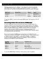
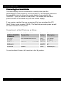
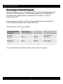
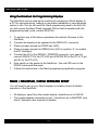
Nav6hub User Guide MAN 3029.00 Issue 1.0 ICS Electronics Limited. Unit V, Rudford Industrial Estate Ford, Arundel, West Sussex BN18 0BD United Kingdom Tel: +44 (0)1903 731101 Fax: +44 (0)1903 731105 E-Mail: Website: [email protected] [email protected] www.icselectronics.co.uk The technical data, information and illustrations contained in this publication were to the best of our knowledge correct at the time of going to print. We reserve the right to change specifications, equipment, installation and maintenance instructions without notice as part of our policy of continuous product development and improvement. No part of this publication may be reproduced, stored in a retrieval system or transmitted in any form, electronic or otherwise without permission in writing from ICS Electronics Ltd. No liability can be accepted for any inaccuracies or omissions in the publication, although every care has been taken to make it as complete and accurate as possible. Copyright 2002, ICS Electronics Limited. All rights reserved. 1 Nav6hub User Guide Important Information This equipment is not approved for use by SOLAS convention vessels within the Global Maritime Distress and Safety System (GMDSS) It is intended for use by leisure craft and other non-SOLAS vessels wishing to participate within GMDSS Safety Warnings This instrument is for use as an aid to sailors and should not lead to a reduction in the level of good seamanship required at all times Reception of messages cannot always be guaranteed as this depends on local radio propagation 2 Nav6hub User Guide Contents QUICK START ....................................................................... 4 INTRODUCTION .................................................................... 4 HOW TO OPERATE YOUR NAV6HUB ................................. 6 NAV6HUB SETUP ................................................................. 6 NAV6 / NAV6PLUS / NAV6 REPEATER SETUP ................ 13 INSTALLATION ................................................................... 14 CONNECTING TO A POWER SUPPLY .............................. 20 MAINTENANCE AND TROUBLE SHOOTING .................... 23 SYSTEM FAULT FINDING .................................................. 23 NMEA DATA COMBINER OPERATION ............................. 25 WARRANTY......................................................................... 26 PACKING LIST AND OPTIONS........................................... 26 SPECIFICATIONS................................................................ 27 NAV6HUB PCB OUTLINE ................................................... 28 Congratulations on purchasing this superb ICS Electronics Ltd product. We hope that it gives you many years of reliable and trustworthy service. Please take the time to read this manual carefully as it contains some essential information regarding the operation and maintenance of the product and a useful background to the NAVTEX system. We recommend that you regularly visit the ICS website www.icselectronics.co.uk for information on updates, the availability of software enhancements, further options and support. The support pages contain frequently asked questions about the Nav6 that you may find useful. There is also a NAVTEX database providing a list of operational NAVTEX stations and their details. The IMO and various national coastguards also operate informative websites that you may wish to visit; check out our links at www.icselectronics.co.uk 3 Nav6hub User Guide QUICK START You will find this product easy to install & operate • Follow the installation guidelines • • • Re-check the cable connections Apply power Set up the Nav6 displays so that the one connected to the DISPLAY1’ connector is ‘master’ and any other displays are ‘slave’ • • You can now share Nav6 Navtex and/or NMEA data between displays If you have the NMEA Data Combiner option fitted then you will also have a combined source of NMEA data available to other systems on your vessel INTRODUCTION It is possible to connect multiple Nav6 displays and sensors together to form an extended system. This may be necessary when more than one sensor is required or multiple displays are needed at several locations on the boat. All systems consisting of more than a single display and sensor require a Nav6hub to facilitate the interconnection. Why Do I Need a Nav6hub ? The Nav6 communicates between the display and the sensor using RS485, which is a 2 wire serial interconnection system widely used in electrically noisy environments. Good performance relies upon using ‘best-practice’ wiring layout for the entire installation. Ideally, the installation should consist of a single twistedpair wire ‘daisy chained’ from one unit (display or sensor) to the next with no ‘stubs’ or ‘loops’. In addition each end of this single wiring run must be terminated with a termination resistor. Obviously these requirements are very difficult, if not impossible, to achieve on a boat. In particular, adding further units to a system that has been installed with ‘best practice’ will be very difficult indeed. Consequently ICS have developed a Nav6hub product in order to ease the installation issues whilst still maintaining bestpractice wiring. 4 Nav6hub User Guide The Nav6hub : a Description The Nav6hub provides two RS485 ports (Port1 consisting of the DISPLAY1 & SENSOR1 connectors and Port2 consisting of the DISPLAY2 & SENSOR2 connectors). Each port can be used to connect to two Nav6 units (any combination of display, sensor or other Nav6hub). The correct termination for RS485 is built into each Nav6 sensor & display, thus the installer only has to set a few links on the Nav6hub. Each Nav6 sensor & display should be wired directly back to a Nav6hub using ICS Nav6 sensor and display cable extensions if required (see the options list at the end of this User Guide). • • • All Nav6 unit connections must be made at a Nav6hub All connections to the Nav6hub and to any Nav6 product should be made with cable supplied or specified by ICS The cable screen drain wire must always be connected as indicated The Nav6hub is the basic interconnect product. If more than one source of NMEA data is present on your vessel, then you may wish to add the NMEA Data Combiner module which fits inside the Nav6hub. The Nav6hub In a Nav6 or Nav6plus Navtex system the Nav6hub can be used to share Navtex messages between several displays, as they are received. The Nav6hub also allows more than one sensor to be connected to the display(s). The Nav6hub can also be used to share a single source of NMEA data between several displays. The Nav6hub plus NMEA Data Combiner In addition to the standard Nav6hub features : The Nav6hub plus NMEA Data Combiner can also be used to share up to four sources of NMEA data between several displays. This combined NMEA data stream is also available to other external systems. Please read the installation section of this user guide thoroughly before attempting installation of the NAV6hub. 5 Nav6hub User Guide HOW TO OPERATE YOUR NAV6HUB The Nav6hub requires no additional control or set-up once it has been configured correctly. The Nav6hub acts as passive interface between other Nav6 products (and between NMEA sources if the NMEA Data Combiner option is fitted). NAV6HUB SETUP Configuring the Nav6hub The Nav6hub contains 5 linker groups which must be set correctly for reliable operation of the Nav6hub (the Nav6hub may work with different linker settings to those indicated, but it is strongly recommended that the published settings are adhered to). Linker group LK1 Name PORT1 COMMS LK2 PORT2 COMMS LK3 SERIAL LK4 NMEA LK5 PROG Function Controls termination of Port1 RS485 Controls termination of Port2 RS485 Sets Printer or PC Serial operation Enables use of the NMEA Data Combiner Allows programming of master display LK1 & LK2 : COMMS Settings LK1 & LK2 allow different combinations of displays and sensors to be connected to the two ports. These linkers apply the correct termination resistors for different combinations of displays and sensors. The linkers should be set as tabulated below : 6 Nav6hub User Guide Configuration Connector LK1 linkers LK2 linkers Sensor Sensor 1 LK1A no fit LK2A fit Master Display Display 1 LK1B no fit LK2B fit - - LK1C no fit LK2C fit - - Example Configuration 1 Example Configuration 2 Sensor Sensor 1 LK1A no fit LK2A fit Master Display Display 1 LK1B no fit LK2B no fit Display Display 2 LK1C no fit LK2C fit - - Example Configuration 3 Sensor Sensor 1 LK1A fit LK2A no fit - - LK1B fit LK2B no fit Master Display Display 2 LK1C fit LK2C no fit Display Sensor 2 Example Configuration 4 Sensor Sensor 1 LK1A no fit LK2A no fit Master Display Display 1 LK1B no fit LK2B no fit Display Display 2 LK1C no fit LK2C no fit Display Sensor 2 Example Configuration 5 Sensor Sensor 1 LK1A no fit LK2A no fit Master Display Display 1 LK1B no fit LK2B no fit Display Display 2 LK1C no fit LK2C no fit Sensor Sensor 2 Example Configuration 6 Sensor Sensor 1 LK1A no fit LK2A no fit Master Display Display 1 LK1B no fit LK2B no fit Display Display 2 LK1C no fit LK2C no fit Display Sensor 2 * Example Configuration 5 assumes 2 switchable sensors, all other configurations assume 1 dual sensor 7 Nav6hub User Guide Example Configurations ICS ICS MASTER SLAVE Configuration 2 SLAVE ICS ICS ICS MASTER SLAVE Configuration 4 For the linker settings corresponding to these example configurations – see the previous table. 8 Nav6hub User Guide LK3 : SERIAL Settings LK3 A B Selection Selects RS232 communications for PC Interface Selects RS232 communications for Nav6 Printer Interface LK4 : NMEA Settings LK4 A B Selection Enables NMEA Data Combiner operation Single NMEA input on NMEA.1 connections LK5 : PROG Settings LK5 Fit No fit Selection For programming master Nav6 display only Normal operation of master Nav6 display The PROG linker should only be fitted whilst the display connected to DISPLAY1 connector is being reprogrammed with a new station database, a new language option or new firmware. This linker should NOT normally be fitted. Connecting a Single Source of NMEA Data Important Information If there is only one source of NMEA data – you must use the “NMEA.1” input connector The Nav6plus display can be connected to a source of NMEA 0183 compatible data. A typical source of NMEA data is a GPS unit. The Nav6hub is conveniently configured so that in an installation with multiple displays, the NMEA data is routed to two displays plus an NMEA output port, and only puts a single electrical load on the NMEA source. The NMEA output is a buffered version of the NMEA input. 9 Nav6hub User Guide Displays connected to the ‘display 1’ and ‘display 2’ ports automatically have NMEA fed to them. A display connected to ‘sensor 1’ or ‘sensor 2’ ports does not, and the following additional connections need to be made : Nav6hub NMEA OUT Connector +VE (A) -VE (B) Display Cable Twisted Pair Core Colour BLUE twisted with BLACK BLUE BLACK Nav6 Display Signal Description NMEA IN +ve (A) NMEA IN –ve B) To use the NMEA.1 input as the single NMEA input, LK4 must be in the ‘B’ position. Connecting to More than one Source of NMEA Data It is not uncommon to have more than one source of NMEA data. For instance a GPS may be transmitting position-related data on one NMEA source and an instrument system may be outputting the boat’s instrument data on another NMEA source. NMEA outputs cannot be connected together and a suitable ‘NMEA combiner’ must be purchased. ICS recommend that you purchase the Nav6hub NMEA Data Combiner option for installation within the Nav6hub. There are four pairs of NMEA input connections on the Nav6hub pcb. These are prioritised with NMEA.1 the highest priority. These means that if an NMEA sentence (say RMC) is presented on NMEA.1 & NMEA.2 connectors then the RMC sentence from NMEA.1 will be used & the sentence from NMEA.2 will be discarded. Nav6hub NMEA IN Connectors NMEA.1 NMEA.2 Priority Suggested Use Highest Second Master GPS Back-up GPS NMEA.3 NMEA.4 Third Lowest Plotter, Radar etc Instruments (Echosounder, Log etc) To use the NMEA Data Combiner, LK4 must be in the ‘A’ position. 10 Nav6hub User Guide Connecting to a Serial Printer The Nav6 display can be connected to a serial printer (see the Nav6/Nav6plus User Guide for more information). The Nav6hub preserves this capability but only allows the master display (connected to the ‘DISPLAY 1’ port) to connect to the printer. This means that the Nav6 printer function is controlled only from the master display. If you require a printer then we recommend that you purchase the ICS Nav6 Printer (order number 918.00). The Nav6hub provides power as well as communication to this printer. Connections to a Nav6 Printer are as follows : Nav6hub SERIAL/PRINTER Connector 12V OUT 0V OUT Nav6 Printer Cable Twisted Pair Core Colour Signal Description RED twisted with BLACK RED BLACK 12V output 0V output SERIAL A SERIAL B BROWN twisted with WHITE BROWN WHITE TX from Nav6 0V SCREEN Screen Silver Nominally 0V To use the Nav6 Printer, LK3 must be in the ‘B’ position. 11 Nav6hub User Guide Connecting to a Personal Computer The Nav6 display can be connected to a PC (see the Nav6/Nav6plus User Guide for more information). The Nav6hub preserves this capability but only allows the master display (connected to the ‘display 1’ port) to connect to the PC. If you require to connect to a PC we recommend that you purchase the ICS PC Interface Cable (order number 6020.09). Connections to a PC are as follows : Nav6hub SERIAL/PRINTER Connector 12V OUT 0V OUT PC Connections 9 way D-type Core Colour Signal Description Pin 5 BLACK No connection 0V output SERIAL A SERIAL B Pin 3 Pin 2 BROWN WHITE TX from Nav6 RX to Nav6 SCREEN Screen Silver Nominally 0V To use the Nav6 PC Interface, LK3 must be in the ‘A’ position. 12 Nav6hub User Guide Using the Nav6hub for Programming Displays The Nav6hub can be used as the method of connecting a Nav6 display to a PC for reprogramming, loading a new station database or new language option in situ. You do not need the Nav6 programming lead to do this, but you will require the Nav6 Flash Upgrade CDrom that is supplied with the programming lead (order number 6030.00). 1. To perform any of the above operations first switch off power to the Nav6hub 2. Connect the display to be updated to the DISPLAY1 connector 3. Place a jumper across the PROG link (LK5) 4. Place a jumper across the SERIAL link (LK3) in position ‘A’ (to enable the PC Interface) 5. Connect the PC to the SERIAL / PRINTER connector (you need to connect RS232 TX to the PC’s RX pin & RS232 RX to the PC’s TX pin and 0V to the PC’s 0V) 6. Now switch on the power to the Nav6hub – the red LED next to the PROG link should illuminate 7. Follow the instructions in the Nav6 programming application program NAV6 / NAV6PLUS / NAV6 REPEATER SETUP You will need to set up your Nav6 displays to enable correct & reliable operation of the Nav6hub. • • All displays, apart from the master display, should be set to SLAVE The master display connected to port 1 should be set to MASTER (see Nav6 / Nav6plus user manual for details) 13 Nav6hub User Guide INSTALLATION Designing a Nav6 System Installation Follow these simple steps : • First decide how many Nav6hubs are required • • • • • Next select the best position for the Nav6hub Now select the position for each Nav6 display and sensor Complete the wiring by following the instructions given in this manual Configure the Nav6hub linkers Check the wiring & configuration • Apply power & test the system How Many Nav6hubs Do I need ? You will usually only require one Nav6hub (for systems with 4 or less units eg. 3 displays and 1 sensor). If you think that you need more than one Nav6hub then please contact the ICS Electronics Technical Helpline for further advice. Telephone +44 (0)1903 738706 Facsimile +44 (0)1903 738747 Email: [email protected] 14 Nav6hub User Guide Mechanical Installation of the Nav6hub Installation of the Nav6hub is straightforward and can be carried out with just a drill and screwdriver. Select the best position for the Nav6hub, this should be a dry location and at least 0.5metre from any receiving/transmitting equipment or flux gate compass. Ensure that there is sufficient room to route the various cables into the Nav6hub. • • Remove the cover from the Nav6hub Position the Nav6hub on a vertical, flat bulkhead or other suitable surface, allowing the cables to exit out of the slot at the base of the unit • • • Mark through the centre two fixing holes Drill two 2.5mm holes into your bulkhead Attach the Nav6hub with the screws provided • • Complete the wiring following the instructions in this user guide Use the cable ties to restrain the wiring from any vibration that might weaken it over a prolonged period • The connecting cables should be restrained from movement by securing them to the bulkhead or to adjacent woodwork • The cover should be replaced when the wiring is complete, the configuration established & the installation tested IMPORTANT The Nav6hub should not be mounted in a position where spray can reach it in a rough sea, or where it is exposed to direct sunlight. 15 Nav6hub User Guide Installation of Displays & Sensors The Nav6 displays and sensors should be located following the guidelines in the Nav6/Nav6plus/Nav6aplus User Guides. Cable runs should be kept away from sensitive equipment, extreme heat, standing water and solvents. It may be necessary to purchase cable extensions to complete the runs back to the Nav6hub. Electrical Installation of the Nav6hub It does not matter which unit is connected to which RS485 port on the Nav6hub – but 2 of the connectors are pre-selected as ‘display’ ports and have all 12 connections marked up on the terminal blocks. One is marked “MASTER” and it is recommended that this be used to connect to the master display. The other two ports are ‘sensor’ ports and only have 5 connections on the terminal block. If more than 2 displays are to be connected then the sensor ports can be used to connect to the power & RS485 connections of the display. See later sections for further details. Decide which is to be the ‘master’ display – connect this to ‘display 1’ on the Nav6hub. • Only the master display can be connected to the optional Nav6 printer or to a PC • Only the master display can be re-programmed in-situ Note that the master display must be set to ‘master’ on the Navtex Set-up page, all other displays must be set to ‘slave’. 16 Nav6hub User Guide Connecting Displays to the Nav6hub The first 2 displays should be connected to ‘DISPLAY1’ and ‘DISPLAY2’ following the printed colour codes on the Nav6hub pcb. Connect all of the wires – except the BLACK paired with GREEN, which is not used. Nav6hub DISPLAY Connector Nav6 Display Cable Twisted Pair Display Cable Core Colour Signal Description RED RED paired with BLACK RED 12V OUT BLACK 0V OUT BROWN SERIAL A BLACK SERIAL B GREEN PROG (NOT USED) (NOT USED) BLUE NMEA IN + BLACK NMEA IN - YELLOW (NOT USED) BLACK (NOT USED) WHITE RS485_A BLACK RS485_B SILVER Nominally 0V BLACK BROWN BROWN paired with BLACK BLACK GREEN GREEN (BLACK pair not used) BLACK BLUE BLUE paired with BLACK BLACK YELLOW YELLOW paired with BLACK BLACK WHITE WHITE paired with BLACK BLACK SCREEN Screen The diagram to the left shows a display connected to the DISPLAY1 (MASTER) connector. 17 Nav6hub User Guide Connecting a Third Display to the Nav6hub A third display can be connected to ‘sensor 2’ if required. When a display is connected to a ‘SENSOR’ connector, the connections should be as shown in the following table: Nav6hub SENSOR Connector YELLOW BLACK Nav6 Display Cable Twisted Pair Display Cable Core Colour Signal Description RED paired with BLACK RED BLACK 12V OUT 0V OUT WHITE BLACK WHITE paired with BLACK WHITE BLACK RS485_A RS485_B SCREEN Screen SILVER Nominally 0V Connecting Sensors to the Nav6hub The first 2 sensors should be connected to ‘SENSOR1’ and ‘SENSOR2’ respectively, following the printed colour codes on the Nav6hub pcb. Nav6hub SENSOR Connector Nav6 Sensor Cable Twisted Pair Sensor Cable Core Colour Signal Description YELLOW YELLOW paired with BLACK YELLOW 12V OUT BLACK WHITE WHITE paired with BLACK BLACK SCREEN Screen (yellow stripe) WHITE (black stripe) RS485_A BLACK (white stripe) RS485_B SILVER 18 (black stripe) BLACK 0V OUT Nominally 0V Nav6hub User Guide The diagram to the left shows a sensor connected to the SENSOR1 connector. Connecting to Another Nav6hub A second Nav6hub can be connected by using a sensor extension cable as follows : Nav6hub SENSOR Connector Nav6 Sensor Extension Cable Twisted Pair Sensor Cable Core Colour Signal Description YELLOW YELLOW paired with BLACK YELLOW (black stripe) Do not connect BLACK (yellow stripe) Do not connect WHITE (black stripe) RS485_A BLACK (white stripe) RS485_B BLACK WHITE WHITE paired with BLACK BLACK SCREEN Screen SILVER Nominally 0V Note that the connections are identical at both ends of the cable. • The second Nav6hub should only have ‘slave’ displays connected to it • There should always be only one ‘master’ display in the system • Use a separate switched & fused power feed from the vessel’s 12V supply to provide power to the second Nav6hub 19 Nav6hub User Guide CONNECTING TO A POWER SUPPLY Protection Devices & Wiring - Power Requirements It is necessary to calculate the total power consumption of the Nav6 system in order to specify the protection devices and power feed cable. The internal power requirement for the Nav6hub is approx 20 mA To calculate the total power consumption for your system and hence the requirement for the external fuse/cct breaker and the loading on your power supply : Each sensor requires 70mA Each display requires 300mA Don’t forget to include the consumption of the printer, if fitted Unit Current consumption Number fitted /mA Nav6hub 20 NMEA Data Combiner 60 Display 300 Sensor 70 Printer 200 1 Total current consumption /mA 20 TOTAL Fuse / circuit breaker requirement An appropriately rated fuse and/or circuit breaker should be used to protect the Nav6 system. The rating should be 1.5 times the total current required by the system. 20 Nav6hub User Guide Power Supply Wiring The main 12V feed wiring (+12V and 0V connections to the Nav6hub) should be rated appropriately. The rating should be at least twice the total current required by the system. ICS do not provide the wire for this connection. The installer should source appropriate marine grade wiring. Note that the fuse / circuit breaker rating should always be lower than the cable rating so that the cable is adequately protected. The Nav6hub should be powered from a nominal 12Vdc switched supply, capable of providing the total current as calculated above. • To allow the unit to be isolated for service, a circuit breaker (or a fuse and switch) should switch the power supply to the Nav6hub • The connection to the boat’s power supply should be made with a suitably rated cable • • Carefully check all connections before applying power Note that vessels that require isolation may need to install a DC to DC converter – if in doubt ask your dealer • 24V vessels should install the 24V / 12V DC to DC converter (see options list) 21 Nav6hub User Guide Testing The Nav6 After Installation • Switch on the Nav6hub by applying 12V to its power connections • • The red “POWER” LED will illuminate The various Nav6 displays and sensors will complete their power-up sequence and then start communicating to each other within a few seconds. The two red LEDs marked PORT1 & PORT2 will start to flash • The Nav6hub is now operational Test the interfaces between the Nav6hub and the various display and sensors as follows : • • Check that all of the Nav6 displays are powered up Check that none of the Nav6 displays shows “ERR” on the status bar at the top of the LCD • If a GPS is fitted then check that the “GPS” icon is displayed on the status bar at the top of the LCD on all displays • If a GPS is not fitted, but there is another source of NMEA data, then check that the Navigate pages display the correct data on all Nav6 displays. (If latitude & longitude are not available on the NMEA bus then the “GPS” icon will not be present) If any of these checks reveal a problem then follow the fault finding guide at the end of this manual. Safety Warning The ICS Nav6hub has been designed and manufactured to be completely safe when installed in accordance with these installation instructions. It is essential that a fuse or circuit breaker be installed in the supply cable. 22 Nav6hub User Guide MAINTENANCE AND TROUBLE SHOOTING Cleaning The Nav6hub may be cleaned when necessary by wiping with a cloth dampened with fresh water. Do not use solvents. SYSTEM FAULT FINDING The Nav6hub is provided with 3 status LEDs. The one marked ‘POWER’ on the pcb should always be lit when power is applied to the Nav6hub. The other 2 LEDs indicate the status of communications on the 2 RS485 ports. Each LED is only ON when a unit (display or sensor) is talking. The only units that talk are sensors and the ‘master’ display. The units talk 4 times per second for a very short period each time. Thus the LEDs appear to flash ON for a short time. LED Status Indicates Possible Causes POWER LED off No 12V to Nav6hub • • No 12V to Nav6hub Fuse tripped PORT1 LED not flashing No communications on Port1 • No talking units connected to Port1 • Check connections to Port1 Set one display to ‘master’ • No talking units connected to Port2 Check connections to Port1 Set one display to ‘master’ • PORT2 LED not flashing No display set to ‘master’ • • 23 Nav6hub User Guide Fault Possible Causes ‘ERR’ on the top line of all displays No sensor connected All displays have been set to ‘slave’ – one sensor must be set to ‘master’ More than one display has been set to ‘master’ RS485_A & RS485_B have been reversed Navtex messages appear to have blocks of 4 or 5 characters missing The termination has not been set correctly – see section 2.1.4 above More than one display has been set to ‘master’ ‘ERR’ on one display but not on all Connections to that display are incorrect If an error condition persists, turn the Nav6 system off and on again and repeat the checks. If any item on the self check list fail a second time, contact your suppler for advice or contact the ICS Electronics Technical Helpline for assistance. Telephone +44 (0)1903 738706 Facsimile +44 (0)1903 738747 Email: [email protected] 24 Nav6hub User Guide NMEA DATA COMBINER OPERATION If you wish to understand how the NMEA Data Combiner operates in order to merge several NMEA data streams, then please read this section. What happens if the same sentence appears on more than one NMEA input ? Ffor example, I have 2 gps receivers – won’t the Nav6 get confused ? No. The NMEA Data Combiner may be used to merge up to 4 NMEA data streams. These are prioritised so that when a particular sentence identifier is detected on two or more inputs, the one from the highest priority channel is used. The other sentences from the lower priority channels are ignored. Your two gps receivers will be connected to two different NMEA inputs. Select one as the master and make sure that it is connected to the highest priority channel ( lowest of the two channel numbers). What happens when there is more NMEA traffic on the inputs than can possibly be supported on a single output ? NMEA 0183 operates at 4800 baud and with a 10 bit data word. Therefore only 480 characters can be sent to the NMEA output per second. In theory this capacity can be exceeded and some valid data lost.. In practice this is unlikely. Care should be taken in selecting which data stream is to be connected to which input. Also ensure that the data repeat-rate from NMEA sources is not set higher than it needs to be (this may be an option on some GPSs and compasses). If an NMEA source becomes disconnected or fails, how quickly will this be detected by the NMEA Data Combiner ? The NMEA Data Combiner detects the loss of one of its inputs in 10 seconds. At this time, if any of the sentences that were present in the lost channel are also present in another lower priority channel then that version will now be transmitted instead. If the input recovers or is re-connected then the NMEA Data Combiner reverts to transmitting the higher priority version of the sentence. 25 Nav6hub User Guide WARRANTY ICS Electronics Ltd warrants to the original end-user that this product will be free from defects in materials and workmanship for a period of one year from the date of purchase. During the warranty period, and upon proof of purchase, the product will be repaired or replaced (with the same or a similar model, which may be a refurbished model) at ICS Electronics’ option, without charge for either parts or labour. For warranty repair, the unit must be returned, carriage pre-paid, to the ICS Electronics Ltd. dealer from whom it was first purchased. This limited warranty shall not apply if the product is modified, tampered with, misused, subjected to abnormal working conditions (including, but not limited to lightning and immersion in water) and use with power supplies and other options not specifically recommended by ICS Electronics Ltd. Please contact us for further details of our warranty repair procedure. PACKING LIST AND OPTIONS Packing List For the Nav6hub contents – please see the packing list enclosed. Options The following Nav6hub options are available: Option ICS Part Number 10 metre sensor cable extension 6020.19 30 metre sensor cable extension 6020.18 10 metre display cable extension 6020.22 30 metre display cable extension 6020.23 NMEA Data Combiner Module 050.07 Nav6 Computer Interconnect Cable 6020.09 Nav6 Programming Kit 6030.00 Nav6 Repeater 920.00 Nav6 Printer 918.00 24V to 12V dc-dc converter tba 26 Nav6hub User Guide SPECIFICATIONS Power Consumption 20 mA @12V – note that total power consumption depends upon how many other units are connected to the Nav6hub Physical Height 180mm Width 122mm Weight 300g Depth 36mm Mounting Bulkhead mounting via two self tapping screws (supplied) Cable exits from slot in base of unit Connection All connections made by screw terminal (cable size 26 to 14 awg) Connect to displays and sensors by the cable supplied with those items Connect to ancillary equipment by the cable supplied with that equipment Environmental Not for outside use Unit must be mounted below decks in a suitable dry location Inputs & Outputs Connector Type Direction Product SENSOR1,2 RS485 Bi-directional Nav6hub DISPLAY1,2 RS485 Bi-directional Nav6hub SERIAL / PRINTER RS232 Bi-directional Nav6hub NMEA.1 NMEA 0183 Input Nav6hub NMEA.2,3,4 NMEA 0183 Input Only Available When NMEA Data Combiner Option Fitted NMEA OUT NMEA 0183 Output Nav6hub 27 Nav6hub User Guide NAV6HUB PCB OUTLINE Programming Linker Programming LED Port 1 Linker Port 2 Linker Serial Linker Port Status LEDs NMEA Linker Power LED 28