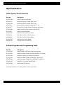
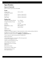
1
NAV6 V2 User Guide NAV6 V2 NAV6plus V2 NAV6repeater V2 NAV6 eNAVTEX Receiver MAN 3030.00 Issue 4.0, March 2013. ICS Electronics Limited Unit V, Rudford Industrial Estate Ford, Arundel, West Sussex BN18 0BF United Kingdom Tel: +44 (0)1903 731101 Fax: +44 (0)1903 731105 E-Mail: [email protected] [email protected] Website: www.icselectronics.co.uk The technical data, information and illustrations contained in this publication were to the best of our knowledge correct at the time of going to print. We reserve the right to change specifications, equipment, installation and maintenance instructions without notice as part of our policy of continuous product development and improvement. No part of this publication may be reproduced, stored in a retrieval system or transmitted in any form, electronic or otherwise without permission in writing from ICS Electronics Ltd. No liability can be accepted for any inaccuracies or omissions in the publication, although every care has been taken to make it as complete and accurate as possible. Copyright 2013, ICS Electronics Limited. All rights reserved. NAV6 Series NAVTEX System User Guide Important Information This equipment is not approved for use by SOLAS convention vessels within the Global Maritime Distress and Safety System (GMDSS) It is intended for use by leisure craft and other non-SOLAS vessels wishing to participate within GMDSS Safety Warnings This instrument is for use as an aid to sailors and should not lead to a reduction in the level of good seamanship required at all times Reception of messages cannot always be guaranteed as this depends on local radio propagation The correct magnetic variation must be input at the navigation instruments (e.g. GPS, electronic compass) for the accurate display of COG, set, waypoint bearing and heading. 2 NAV6 Series NAVTEX System User Guide Contents Quick Start ................................................................................................................................................................................... 5 Introduction ................................................................................................................................................................................. 6 What Is NAVTEX? ................................................................................................................................................................ 6 How Does NAVTEX Work? ............................................................................................................................................... 6 NAV6 Features ............................................................................................................................................................................ 7 The Keypad and Display .......................................................................................................................................................... 9 Viewing and Scrolling through NAVTEX messages ............................................................................................... 10 Message Storage ............................................................................................................................................................... 10 Filter Profiles .............................................................................................................................................................................. 11 Station Selection ................................................................................................................................................................ 11 Message Type Filtering ................................................................................................................................................... 13 NAVTEX View ............................................................................................................................................................................ 15 Viewing NAVTEX Messages ........................................................................................................................................... 15 Printing Individual Messages ........................................................................................................................................ 15 Navigation Views ..................................................................................................................................................................... 16 Position View ...................................................................................................................................................................... 17 Combined View .................................................................................................................................................................. 17 Waypoint View ................................................................................................................................................................... 18 Conning View ..................................................................................................................................................................... 18 Log View ............................................................................................................................................................................... 19 Custom Views ..................................................................................................................................................................... 19 Settings Menu ........................................................................................................................................................................... 20 NAVTEX................................................................................................................................................................................. 20 Navigate ............................................................................................................................................................................... 22 LCD ......................................................................................................................................................................................... 26 General .................................................................................................................................................................................. 27 Database .............................................................................................................................................................................. 31 Installation.................................................................................................................................................................................. 33 Configuration Options ..................................................................................................................................................... 33 Mounting the Display Unit ............................................................................................................................................. 35 Installing the Receiver Unit ............................................................................................................................................ 35 Connecting Power ............................................................................................................................................................. 41 Connecting an NMEA Source........................................................................................................................................ 41 Connecting the Programming Signal ......................................................................................................................... 41 Connecting a PC, Printer or Plotter ............................................................................................................................. 42 Connecting Multiple Display Units .............................................................................................................................. 43 Connecting a Notebook or Tablet PC ........................................................................................................................ 43 Testing The NAV6 After Installation ........................................................................................................................... 44 Maintenance and TroubleShooting ................................................................................................................................... 45 Cleaning................................................................................................................................................................................ 45 Fault Finding ....................................................................................................................................................................... 45 Software Upgrade ............................................................................................................................................................. 46 Fuses ...................................................................................................................................................................................... 46 Warranty ..................................................................................................................................................................................... 47 Glossary....................................................................................................................................................................................... 47 Optional Extras ......................................................................................................................................................................... 48 Specification .............................................................................................................................................................................. 49 Appendix I: NAVTEX Station Database............................................................................................................................. 51 Appendix II: Message Type Indicators .............................................................................................................................. 52 Appendix III: NMEA Sentences Supported ..................................................................................................................... 53 3 NAV6 Series NAVTEX System User Guide NAV6plus Premium System Showing NAV6plus Display Unit, eNAVTEX Receiver Module, Passive Antenna and the NAV6 eNAVTEX PC App. Congratulations on purchasing this high quality ICS Electronics Ltd product. It is not only an excellent NAVTEX receiver, but a first class instrument repeater (plus and repeater models only). It may be the only display you will ever need at your navigation position. We hope that it gives you many years of reliable and trustworthy service. Please take the time to read this manual carefully as it contains some essential information regarding the operation and maintenance of the product and a useful background to the NAVTEX system. We recommend that you regularly visit the ICS website www.icselectronics.co.uk for information on updates, the availability of software enhancements, further options and support. The support pages contain frequently asked questions about the NAV6 that you may find useful. There is also a NAVTEX database providing a list of operational NAVTEX stations and their details. The IMO and various national coastguards also operate informative websites that you may wish to visit; see www.icselectronics.co.uk/links. Please note that the NAV6 standard model does not include the instrument repeater functions as described in this manual. It may be upgraded at any time in the future (charges apply). 4 NAV6 Series NAVTEX System User Guide Quick Start You will find this product extremely easy to operate. Please don't be intimidated by the comprehensive nature of this manual. In reality, receiving your first NAVTEX messages could not be simpler. Follow the installation guidelines Re-check the cable connections Apply power If you have not connected a GPS navigation receiver, make sure that you set the date and time on the screen which will appear at start up. Wait for your first NAVTEX message. If you are within range of a NAVTEX transmitter, you should not need to wait for more than four hours. If you then want to get the best from the system, read the rest of the manual. 5 NAV6 Series NAVTEX System User Guide Introduction What Is NAVTEX? NAVTEX is a worldwide system for the broadcast and automatic reception of maritime safety information (MSI) in English by means of a narrow-band direct-printing telegraphy. NAVTEX provides shipping with navigational and meteorological warnings and urgent information. NAVTEX is a component of the IMO/IHO worldwide Navigational Warning Service (WWNWS) as defined by IMO Assembly resolution A.706(17). It is included within the Global Maritime Distress and Safety System (GMDSS). Since 1 August 1993, NAVTEX receiving capability has become mandatory equipment for certain vessels under the provisions of the International Convention for the Safety of Life at Sea (SOLAS). NAVTEX broadcast information is available to all seafarers, free of charge. How Does NAVTEX Work? NAVTEX transmissions are sent from stations situated worldwide. The power of each transmission is regulated so as to avoid the possibility of interference between transmitters. Each station is allocated a 10-minute time slot every 4 hours so that many stations can share the same frequency. Stations typically have a transmission range of 250 – 300 Nm. 6 NAV6 Series NAVTEX System User Guide NAV6 Features The NAV6 adds a new dimension in NAVTEX functionality. The NAV6 offers simultaneous reception on both the 518kHz international channel and the 490kHz local information channel. Unlike other NAVTEX receivers that discard unselected messages, the large flash memory in the NAV6 means it has the capacity to store all of the messages from transmitting stations within its range. This allows you to recall, display and review any message at any time even if it was not selected at the time of the transmission. A unique message processing (iNEC) feature benefits you by decreasing errors in received messages in noisy or weak signal areas. The NAV6plus includes all the features of the NAV6 standard including dual frequency and when connected to an NMEA data source, it offers a range of standard and custom instrument repeater functions. The NAV6plus includes a database of all NAVTEX stations around the world and when connected to a GPS can be set to automatically display messages from all stations within range or just the closest station helping to provide a much clearer picture of the conditions in your area. Outputs are also included for connection to a serial printer or computer. The NAV6 eNAVTEX Receiver module comes as standard with the NAV6plus. The eNAVTEX receiver includes a USB interface for connection to a PC running the NAV6 eNAVTEX App. It has a large 4MB message store for saving messages when the unit is not connected to a display device. The USB interface can also be used for updates to the receiver and to a connected display unit. The NAV6plus and NAV6repeater include additional instrument repeater functions. All the information you really need at your navigation position on one large, easy to use display. With navigation space becoming more and more restricted in modern boats, the NAV6plus concentrates all the data you need, where you need it. It takes critical NMEA data from your GPS or instrument systems and displays it in a highly innovative manner. An electronic log book is updated at regular intervals and can be sent to a serial printer. These powerful instrument and GPS repeater functions are included as standard in the NAV6plus. The NAV6repeater can also be purchased separately without a NAVTEX receiver for use as a stand-alone NMEA repeater. When added to an existing system, NMEA data and NAVTEX data can also be repeated at another position such as the helm or fly bridge. NAV6 Display Unit The Display Unit uses a high resolution backlit LCD to display NAVTEX messages in a choice of text sizes. The display unit contains a large non-volatile memory to store NAVTEX messages, NAVTEX station database, all of the user settings, filter options, LCD contrast and backlight levels. All messages and settings are retained during power down. Several messages can be displayed at once (depending upon the length of the message) and messages can be scrolled with a single key-press. Messages can be filtered using a number of user selectable settings. The NAV6plus and NAV6repeater can be connected to a printer or computer to print NAVTEX messages and Navigation logs. Audible and visible alarms can be set up to indicate reception of SAR and/or New Messages. 7 NAV6 Series NAVTEX System User Guide A sleep mode allows long standby periods with minimum power consumption, such as when the vessel is left in a marina with main batteries being trickle charged from the shore. eNAVTEX Receiver Unit The Receiver Unit contains dual receivers that can receive on both 490kHz and 518kHz simultaneously. Up to two displays and a PC may be connected to an eNAVTEX receiver for simultaneous operation. 8 NAV6 Series NAVTEX System User Guide The Keypad and Display Softkey 1 Softkey 3 View Indicator Softkey 2 Navigation Pad Softkey 4 The central keys are a ‘navigation pad’ ( UP DOWN LEFT RIGHT ). In Settings screens the RIGHT key will act as an enter key or Change setting or toggle function depending on the context, and the LEFT key will go back to a previous level. Softkeys 1 to 4 are situated on either side of the navigation pad. The current function is shown on the Softkey menu area at the bottom of the LCD. On the NAV6plus the View Indicator shows the number of top level View Screens enabled and highlights the one currently selected. On the top level views the LEFT and RIGHT navigation pad keys will move between Views Screens. The View Screens are enabled or disabled on the General Settings Page. The Softkey 1 is normally the Home key and will take you back to the top level view screens from wherever you are in the menus. Pressing the Home key twice or holding it down for more than 2 seconds will go back to the first View Screen, which is normally the NAVTEX view unless the display is just being used as an instrument repeater. In the top level View Screens the Settings (Sofkey 4) will select the Settings Menu where you can configure the NAV6. On settings that require a change, Softkeys 2 and 3, and will change the value, Softkey 3 will generally increase a value, and Softkeys 2 will decrease it. 9 NAV6 Series NAVTEX System User Guide At the top of the display is a status bar: The status information is displayed as a series of icons. The meaning of the icons is as follows: Message ID for the currently selected message An alarm is active NMEA / GPS position data available 490 kHz reception available 518 kHz reception available Receiving message now Signal Carrier, but no message Receiver Communication fault SAR message received NEW message received UTC Time Viewing and Scrolling through NAVTEX messages To view NAVTEX messages you must first select the NAVTEX View Screen. Press and hold the Home key until the NAVTEX View Screen is displayed. Note: This assumes the NAVTEX View has not been reordered and is still the first View as from the factory. You can now use the UP, DOWN, keys to scroll through the displayed messages. If you press and hold the keys the scroll speed will increase so you can scan through the messages more quickly. The messages currently displayed may be a sub-set of all the messages stored in memory. Whether you can see a particular message or not depends upon the current station selection, message filter and age limit settings (see following sections for details). Message Storage All received NAVTEX messages are stored in memory regardless of whether you have them selected for viewing or not. The NAV6 has lots of memory so you will easily have enough storage for all messages received. The messages displayed are selected from the NAV6 memory by applying filters to show messages from transmitting stations and types of messages required. This enables you to change your mind later about your message display options. This means you will still be able to view messages that were received previously, but were not selected for display at the time, by changing the current station and message filters. 10 NAV6 Series NAVTEX System User Guide Once the message store has filled up new message will start to overwrite the oldest messages in the store. Even in areas with lots of stations and high levels of NAVTEX transmissions message will remain in the store for more than two weeks before they are overwritten. After using the NAV6 for a while you may notice that if you receive a particular message more than once there will only ever be one copy in view. If a message has been received more than once the NAV6 will store only the best version. It even attempts to repair corrupted messages by comparing repeated transmissions of the same message! Filter Profiles The messages currently available for viewing on screen are selected from the messages stored in memory by applying ‘filter profiles’. To see the current selected filter profile select Settings, the profile selected is displayed at the top next to NAVTEX in the Settings Menu. There are three profiles on the standard NAV6 and 5 on the NAV6plus. Each profile has 4 set up pages for 518kHz Stations, 518kHz Message Types, 490kHz Stations and 490kHz Message Types. On the NAV6plus profile 5 is also used to control which messages are automatically printed or sent to the serial interface (see the settings Menus section for more information). In the Settings Menu or any one of the filter pages press Next Prof to change to the next profile number. You will notice that the settings on the screen change with filter profile number. The last profile selected in the Settings Menu is the one that will be used when you return to the NAVTEX message view. You can customise the Filter Profiles so that you can switch quickly between set ups for different viewing requirements, perhaps for sailing in specific areas or viewing particular types of messages. By default the NAV6 is preconfigured with some useful Filter Profiles. You can reset any of the Filter pages back to the defaults at any time by pressing the Reset button on the Settings page. Tip: Use profile 1 for normal operation and use the other profiles if you want to switch between different sets of messages on the display. Station Selection If you leave your NAV6 receiving for a long time you will have received many messages (subject to your current location) and unless you filter out those stations that are not required for display, you will be swamped with data. You can show or hide messages from required station by turning them on and off manually in the Station Filter pages. On NAV6plus the stations displayed can also be done automatically using position information from a GPS receiver. Station Filter selection is made in the Station 11 NAV6 Series NAVTEX System User Guide Filter Pages selected from the Settings Menu. You will notice that each station can be set to one of three filter settings: Setting Operation On Messages from station always in view (see note 1) Off Messages from station never in view Auto Messages from station only viewed when nearest or in range depending upon setting (see note 1) Note 1: messages are only displayed if they also fall within the ageing limit, error limit and message category filter settings. An asterisk to the right of the station name indicates that the station is enabled for viewing with the current filter setting and location. Automatic Station Selection Using GPS (NAV6plus only) Many users will just want to display NAVTEX from their closest NAVTEX station to their cruising location. This can easily achieved by connecting a GPS and setting the Auto Station Filer. The setting can be set to Nearest or In Range. Nearest With Nearest selected only messages from the station closest to your position will be displayed. 12 NAV6 Series NAVTEX System User Guide In Range NAVTEX stations have a declared transmission range which stored in your NAV6’s station database. With In Range selected all the stations that are in Range of your current position will be displayed. Tip: Set stations that you want to ‘automatically select’ to Auto, and stations that you definitely do not want should be set to Off. You may wish to set your ‘home’ station to On so that you display messages from it even if it is currently not the nearest station to your cruising position. Important (NAV6plus Only): You may wish to leave your NAV6plus running whilst your GPS or instrument system is disconnected or switched off. If you do this then please be aware that the Navigate data items derived from NMEA (including position) will time out after a short while. If you have also opted to display only the ‘Nearest’ NAVTEX station or stations ‘In Range’ then the NAV6plus will no longer have the required position data. It will revert to displaying all stations that are set to ‘Auto’. As soon as the NMEA data becomes available again only the ‘Nearest’ or ‘In Range’ stations will be displayed dependent upon your current settings. Manual Station Selection You can manually select a station (or stations) by setting them to On or Off by using the UP, DOWN keys to select then the and Softkeys 2 and 3 or RIGHT key to toggle the setting. If you are using a GPS but still want to select stations manually then do not leave any stations set to Auto. Message Type Filtering You can further reduce the amount of unwanted messages that are displayed by applying a filter to the message types. Select the Message Type Filter Page from the Settings Menu. Each message type can be turned On or Off or can be set to New using the UP, DOWN, and and Softkeys 2 and 3 or RIGHT key to toggle the setting. The figure shows the 518kHz Message Types Filter Page; the 490kHz Types filter page is similar. Each of the message types can be selected as either On, Off or New Set each message type filter to one of the following: Setting Notes On Message type always displayed Off Message type never displayed New Message type only displayed when new. Messages marked as read will not appear. 13 NAV6 Series NAVTEX System User Guide Reading ‘NEW’ Messages Sometimes it is useful to know which messages have been received since you last looked at the NAV6 display. You may have noticed that each message header carries a ‘NEW’ icon and that there is an additional ‘NEW’ icon in the status bar at the top of the display. Select the NAVTEX View and you will see that Softkey 3 is now indicated as Next New. If the message at the top of the display has the ‘NEW’ icon showing then Softkey 2 will now be indicated as Mark Read. Once you have read the message and want to de-emphasise it then press Mark Read. The ‘NEW’ icon will disappear from the message header. Press Next New to jump to the next new message. Proceed through all of the messages in this way. Once all of the messages have been marked as read then the ‘NEW’ icon at the top of the display will also disappear. When you return to the NAV6 later on it is now very easy to tell if there are any new messages to read (the ‘NEW’ icon in the status bar at the top of the display will be illuminated). Note that messages that have been ‘marked as read’ will still be displayed, but with the ‘NEW’ icon removed from the header in each one. It is possible to hide messages once they have been read; go to the Message Type Filter Page and set the message types that you want to hide after they have been marked as read to ‘New’ instead of ‘On’. You may wish to leave SAR messages as ‘On’ so that they are not hidden once read. Displaying the Newest Message All messages are date and time stamped by the NAV6 even if there is no GPS connected and therefore no correct source of time data. If there is no GPS connected then you can manually enter the time and date or just ignore it. The NAV6 will still order the messages in the correct chronological order (remember that the indicated time of reception will be incorrect). Messages are displayed in the NAVTEX View in time descending order i.e. the newest messages will appear at top of the display. Message Ageing NAVTEX messages become less relevant over time and eventually just clutter the display. In order to reduce the number of obsolete NAVTEX messages that are being displayed, the NAV6 uses a message ‘Age Limit’. The NAV6 will hide messages that are older than a certain pre-settable age limit. These messages are still stored in the NAV6plus memory for a considerable time after they have been removed from the display and can still be displayed if necessary by increasing the message age limit setting. 14 NAV6 Series NAVTEX System User Guide To change the age limit select NAVTEX Settings from the Settings Menu. Select Age Limit using the UP and DOWN keys and the Change (or RIGHT) key to select a value. The default setting is three days which is the official time that NAVTEX messages remain valid. Set a longer age limit or none if you wish to display NAVTEX messages going back over the previous weeks. NAVTEX View The NAVTEX View is only available if a receiver is (or has been) connected to the display and the NAVTEX frequency setting on the NAVTEX options page is set to 518kHz, 490kHz or Both. Viewing NAVTEX Messages In the NAVTEX View, the display consists of a large area dedicated to displaying NAVTEX messages, with a status bar at the top, and descriptions of the Softkey functions at the bottom. It is possible to scroll up and down the messages line by line, using the UP and DOWN keys. Holding down these keys will increase the scrolls speed incrementally to aid moving through the message store more quickly. This view can be used for keeping track of new messages as they are received and displayed. Each new message can be accessed by pressing Next New (Softkey 3) and then marked as read, if required by pressing Mark Read (Softkey 2). The Next New Softkey should be used to move the next new message to the top of the NAVTEX display, where it can be marked as read by pressing Mark Read. Note that the message that will be ‘marked as read’ is indicated in the top left of the status bar. This is particularly useful when the message’s header has scrolled off the top of the display area. Printing Individual Messages If enabled the NAVTEX View allows individual messages to be printed (NAV6plus only). The Print Softkey is only displayed if the manual print setting is enabled on the NAVTEX Settings Page. Printing is only possible if an external printer or PC is installed as part of the system. The Next New Softkey can be used to move the next new message to the top of the NAVTEX display where pressing Print will send it to the printer. 15 NAV6 Series NAVTEX System User Guide Navigation Views (NAV6plus or NAV6repeater only) Navigate Views are only available if there is a GPS or other source of NMEA 0183 data connected to the NAV6plus or NAV6repeater NMEA input. The GPS icon in the status bar at the top of the display will be illuminated only if there is position data available on the NMEA input. There are five fixed-format Navigate Views and four Custom Views. These can be selected on the General Settings Page. The five fixed views are: Position View Combined View Waypoint View Conning View Log View The user configurable views are Custom 1,2,3 and 4. Note: Data fields that are not available on the NMEA input are indicated by a series of dashes (e.g. ---.--). Important The correct magnetic variation must be input at the navigation instruments (e.g. GPS, electronic compass) for the accurate display of COG, set, waypoint bearing and heading. For the purposes of testing your installation, you may wish to use your GPS’s simulator mode to generate data for the NAV6plus. Please check your GPS User Manual to find out whether it transmits valid NMEA data whilst it is in its simulator mode – many GPS’s do not set the ‘data valid’ flag in the NMEA sentences during simulation. As a safety feature, the NAV6plus will ignore any NMEA sentences where the ‘data valid’ flag is not set. The NAV6plus also has a built in NMEA simulator mode – please ensure that it is switched OFF in normal operation. 16 NAV6 Series NAVTEX System User Guide Position View The Position View shows GPS information (Position, COG and SOG), Depth reading and Distance log using a large font. Combined View The Combined View shows all NMEA input data on one screen using a small font. 17 NAV6 Series NAVTEX System User Guide Waypoint View The Waypoint View shows waypoint navigation information and a graphical “rolling road” display of the boat position and course relative to the course line. The rolling road display can be used to steer the boat along the course line whilst keeping the cross track error within chosen limits (the XTE limit may be changed on the Navigate Settings Page. The Waypoint View shows the waypoint name, waypoint position, time to go (TTG in hours, minutes and seconds), range and bearing to waypoint, closing speed to way point, cross track error and COG and SOG. The UP and DOWN keys have no function in this View. Conning View The Conning Display is a unique analogue display which shows overlapping vectors for Heading (course through the water), Course Over the Ground (COG), Set (a combination of leeway and tide) and wind. All of these vectors are displayed relative to the current heading, which is displayed in digital form at the top of the screen. Heading is shown as a single headed arrow; Course Over the Ground (COG) is shown as a double headed arrow, and Set is shown as a triple headed arrow - in the familiar manner. The wind vector displays variable tail patterns according to the strength of the wind. It follows the usual meteorological wind symbol rules: 5 kts per half feather, 10 kts per full feather, 50 kts per triangle. Computed Set and Drift and other related parameters are shown in digital form at the bottom of the screen. To take into account various sea states, variable damping levels may be selected by pressing Damping Softkey 2. The currently selected level is shown in the top right hand corner of the display. The damping level can be None, Low, Medium or High. The damping level affects COG, SOG, Heading and Water Speed and Set and Drift readings. The UP and DOWN keys have no function in this View. 18 NAV6 Series NAVTEX System User Guide Log View The UP and DOWN keys allow the log to be scrolled forwards and backwards in time. Use the and Softkeys 2 and 3 to horizontal scroll other LOG data into view. Tip: consider the Log View to be a large piece of paper. The LCD allowing a smaller view which can be moved up, down, left and right displaying a portion of the paper at any one time The Log View columns are Position, COG, SOG, Heading, Water Speed, Wind Direction, Wind Speed, Depth and Distance. Custom Views The four Custom Views can be configured to show either 2, 3 or 4 panels (the figure shows a 3 panel view). Each panel can be configured to show different navigation information from a range of options. See the Customs Views Page under Navigate in the Settings Menu for more details of the available options. 19 NAV6 Series NAVTEX System User Guide Settings Menu The Settings Menu provides access to all the configurable settings of the NAV6 so that it may be set up to operate in a way that suits you best. NAVTEX message display presentation, Navigate data presentation, LCD operation, General settings and the NAVTEX station database are all configured from the Settings Menu. The Settings Menu is divided into five sections NAVTEX, Navigate, LCD, General and Database. NAVTEX The NAVTEX section of the Settings Menu contains the options for the storage and display of NAVTEX messages. NAVTEX Filters Station and Message Filtering are described in the Filter Profiles section earlier in the user guide see page 11. NAVTEX Settings Select NAVTEX Settings to access the NAVTEX Settings Page This page is used for configuring settings such as Font, Display Mode, Sounds and Printing. Use the UP and DOWN keys to select the setting that you want to change. Use the RIGHT key or and Softkeys 2 and 3 to change the setting. The following table details each of the settings available on this page. 20 NAV6 Series NAVTEX System User Guide NAVTEX Settings Page Option Setting Notes Font Small Display NAVTEX messages using small font Medium Display NAVTEX messages using medium font Large Display NAVTEX messages using large font Error Threshold XX % Percentage character error rate above which messages are not displayed. Note that this setting does not stop messages with an error rate above the threshold from being stored in memory Alphabet Latin Latin alphabet used for NAVTEX messages. Cyrillic Latin alphabet with third shift Cyrillic used for NAVTEX messages Age Limit None, 1, 2, 3, 5 Days, 1, 2, 3, 4, 8, 12 Weeks Maximum age of NAVTEX messages to be displayed. NAVTEX messages older than the age limit are not displayed. When set to None all NAVTEX message are displayed. NAVTEX Frequency None No receiver selected. Tip: useful when using the display only as a NMEA instrument repeater 490 kHz 490 kHz only operation 518 kHz 518 kHz only operation Both 490 and 518 kHz operation. New Message Off New message alert off Alert On Audible alarm for new messages Antenna Alarm Off Antenna alarm off Timed Antenna alarms repeated 5 times, unless cancelled Repeat Antenna alarms repeated until cancelled (Press any key to silence the alarm). Off SAR alarm off Timed SAR alarms repeated 5 times, unless cancelled Repeat SAR alarms repeated until cancelled (Press any key to silence the alarm). Master Set to master if this is the main display. This display will control the receiver over the receiver data link. Only one display may be set to master. Slave Set to slave if this is a repeater unit. Slave units do not control the receiver and can only monitor the receiver data link. Auto Print Off Auto printing off (NAV6plus only) On Auto printing on. SAR Alarm Display Mode New messages will be printed when received. The Station and Messages Types sent to the printer is controlled by the settings in Profile 5. Note: Profile 5 does not need to be displayed for this process. Manual Print Off Manual printing off. The NAVTEX View Print Softkey is hidden (NAV6plus only) On Manual printing on. The NAVTEX View, Print Softkey is enabled Output Format Data Formatted for PC. Messages printed in raw format as received. (NAV6plus only) Printer Formatted for printing. Messages printed with print header. Antenna Type Dual Reported by receiver, cannot be changed Firmware Version X.X Reported by receiver, cannot be changed Hardware Revision X Reported by receiver, cannot be changed Factory settings are shown in bold. 21 NAV6 Series NAVTEX System User Guide Monitor NAVTEX Page The monitor page shows a split screen view of live 490 and 518 kHz transmissions as they are received. None of the filtering selected in the various setup pages is applied. The monitor page displays ALL incoming data regardless of error rate. The monitor page also shows the low level phasing characters contained within transmissions (shown as ø characters) and transmission errors (shown as * characters). Navigate The Navigate section of the Settings Menu contains the options for controlling the display of the Navigation Views. Navigate Settings (NAV6plus and NAV6repeater only) The Settings Menu Navigate section is used for configuring the top level Views that display Instrument Repeater functions. The Navigation Views are described earlier in the guide, this section explain the Navigate Setting Page, the Custom View Settings and NMEA monitoring tool. Navigate Settings Page The Navigate Setting Page controls details of how the Instrument Repeater functions will appear with setting such as units of measurement and reference types. 22 NAV6 Series NAVTEX System User Guide The table below describes each of the Navigation Settings Page options. Option Setting Notes Distance Units NM Nautical Miles km kilometres mi Miles Kt Knots Km/h Kilometres per hour m/s Metres per second mph Miles per hour ft Feet m metres True COG and waypoint bearings displayed relative to true North Magnetic COG and waypoint bearings displayed relative to magnetic North True Heading and set displayed relative to true North Magnetic Heading and set displayed relative to magnetic North Kt Knots Km/h Kilometres per hour m/s Metres per second mph Miles per hour True True wind speed and direction displayed Relative Relative wind speed and direction displayed Damping None, Low, Medium, High Sets the damping level applied to COG, SOG, Heading, Water Speed, Set and Drift readings. Demo Mode Off Real navigation data from the NMEA input is displayed. On Simulated navigation data is displayed. Note: the GPS icon does not appear on the status bar. 4800 Original NMEA speed 38400 High Speed NMEA XTE Limit 0.02 to 1 NM Set the cross track error limit used on the Waypoint View. Increments in 0.01 NM units. Log Interval OFF 15, 20, 30 mins 1, 2, 3, 4, 6, 12 hours Logging interval as selected. Auto Print Off Auto printing off On Auto printing on. Log data will be printed at the log interval. Off Manual printing off. The Print softkey on the Navigate Mode, Log View is hidden On Manual printing on. The Print softkey on the Navigate Mode, Log View is enabled Speed Units Depth Units North Reference Heading Reference Wind Speed Units Wind Reference NMEA Speed Manual Print Factory settings are shown in bold. 23 NAV6 Series NAVTEX System User Guide Custom Views Settings Access the Custom View Settings from the Settings Menu to show settings for the Custom Navigation Views Screens. Set the format for each user view page to either Off, 2, 3 or 4 panels. Set the contents of each panel. Panel 1 is displayed at the top and panel 4 is at the bottom of the page. Use the UP and DOWN keys to select the setting that you wish to edit. Use the and Softkeys 2 and 3 or RIGHT key to change the setting. Note: The overall control of which Views are available at the top level and the order they appear is set up on the General Settings Page. Option Setting Notes Format Off Disable the user view page 2 Panels Display the user view page with two large panels. 3 Panels Display the user view page with one large panel at the top and two small panels at the bottom. 4 Panels Display the user view page with four small panels. See right Choose the data to be displayed in large panels from the following: Panel n Time, Date, Position, COG, SOG, Heading, Water Speed, Wind Direction, Wind Speed, Set, Drift, Distance, Trip, Depth, Turn Rate, Waypoint, Wpt Position, Range, Bearing, TTG, Closing Spd, XTE. Choose the data to be displayed in small panels from the following: Time/Date, Latitude, Longitude, Ground, Water, Wind, Current, Odometer, Depth, Turn Rate, Waypoint, Wpt Latitude, Wpt Longitude, Range/Bearing, TTG, Closing Spd, XTE. 24 NAV6 Series NAVTEX System User Guide Monitor NMEA The Monitor NMEA page shows a view of live NMEA0183 data received at the NMEA input. The monitor page displays ALL incoming sentences and can be paused by pressing the Pause Softkey. 25 NAV6 Series NAVTEX System User Guide LCD The LCD section of the Settings Menu has one option to access the LCD Settings page. LCD Settings Page The LCD Settings Page shows a checker board pattern that can be used to set up the LCD. LCD contrast is adjusted with the LEFT and RIGHT keys or and Softkeys 2 and 3. LCD brightness is adjusted with the UP and DOWN keys. There is a readout of the LCD backlight temperature towards the bottom of the display. This is internal case temperature, and gives only an approximation to ambient temperature. The LCD setting has three modes that are selected using Softkey 4 Day, Night and Sleep. Different Contrast and Brightness levels may be set for each mode. In Sleep mode the display will turn off completely after a period of 30 seconds of activity and blink the RED LED every 15 seconds. Pressing any key will temporarily wake the display from sleep mode. Note: You will need to use the Home Softkey 1 to exit the LCD settings Page. Tip: If the LCD is unreadable due to incorrect contrast setting, hold down the Settings (Softkey 4) for more than 2 seconds, in any operating mode, to display the LCD page, set the Day mode and reset the LCD contrast and backlight to 50%. The LCD should now be readable. Adjust the contrast as required. 26 NAV6 Series NAVTEX System User Guide General The General section of the settings Menu has one option to access the General Settings Page. General Settings Page This view shows general settings for the NAV6 display such as Date, Time, Sound, Miscellaneous settings and the top level View controls. Use the UP and DOWN keys to select the setting that you wish to edit. Use the and Softkeys 2 and 3 or RIGHT key to change the setting. For a NAV6plus in the View Settings section, Softkeys 2 and 3 will change to and and may be used to change the order of the top level views. The Change Softkey 4 or RIGHT key should be used to enable of disable the view. Note: Date and time will be taken from NMEA input data if available. There is no battery backup so date and time will be incorrect when power is switched on unless NMEA data is available or the date and time are manually set. The date and time is used to mark all incoming NAVTEX messages so that they can be sorted by date and time. Option Setting Notes Year YYYY Year, e.g. 2001 Month MM Month, e.g. 03 Day DD Day, e.g. 15 Hour HH 24 hour clock Minute mm Minutes Keyclick OFF No beep on key press ON Beep on key press New Message OFF New message alert off Alert ON Audible alarm for new messages Antenna Alarm OFF Antenna alarm off Timed Antenna alarms repeated 5 times, unless cancelled Repeated Antenna alarms repeated until cancelled OFF SAR alarm off Timed SAR alarms repeated 5 times, unless cancelled Repeat SAR alarms repeated until cancelled English English language menus Francais French language menus Portugues Portuguese language menus Deutsch German language menus SAR Alarm Language 27 NAV6 Series NAVTEX System User Guide Option Setting Notes LED Function OFF LED always off ON LED as power indicator RX LED as receive indicator SAR LED as SAR indicator NEW LED as New Message indicator View Settings Enabled This section is used to turn on or off which View Screens are NAV6plus and NAV6repeater only Disabled visible and the order in which they appear. Defaults shown in bold. Alarm Operation The NAV6 display contains a buzzer that can generate audible alarms for the following conditions: Option Notes New Message Alert Short beep beep. Not repeated. Indicates reception of a new NAVTEX message. SAR Alarm Morse code: Dot dot dot, dash dash dash, dot dot dot.. Repeated every ten seconds. Indicates reception of a message type D, Search And Rescue NAVTEX message. Antenna Alarm Short dah dee, dah dee. Repeated every eight seconds. Indicates that there is a fault in the NAVTEX antenna or the cabling; see the Fault Finding section for more details. The alarms can be enabled or disabled via the General Settings Page. When enabled, the SAR Alarm and Antenna Alarm can be set to repeat 5 times or to repeat continuously. Tip: When an alarm is active, pressing any of the Softkeys will cancel the alarm. The normal Softkey action will not occur. Tip: When an alarm is active, an alarm bell icon will flash on the status bar. LED Function The red LED found above the Softkeys, can be set on the General Settings Page to flash when there are unread new messages or SAR messages. This can be useful in a noisy environment where audible alarms cannot be easily heard. View Settings (NAV6plus and NAV6repeater only) This section is used to turn on or off which View Screens are visible and the order in which they appear. Use the UP and DOWN keys to select the View and the Change Softkey or RIGHT key to change the setting. Use the and Softeys to change order in which the View Screens are displayed. 28 NAV6 Series NAVTEX System User Guide Printer or Serial Data Output* If Printer or PC is connected to the Serial Output the NAV6plus can be set to send individual or new messages as they arrive (see Auto and Manual Print on the NAVTEX Settings Page) to the Serial Output. It can also be configured to output the Navigation Log to the printer. Note: the Stations and Messages Types sent to the Serial Output in Auto Print Mode are controlled by the Filters in profile 5. Profile 5 does not need to be the one currently selected for Viewing. When configured for printing the NAV6plus functions like a GMDSS paper NAVTEX printer when connected to a suitable serial printer. A suitable serial printer can be purchased from ICS (ICS part number ICS.918.01). The NAVTEX auto print facility acts like a GMDSS paper NAVTEX printer: Poor quality messages (error rates over 33%) are not printed. All new messages are printed when first received. Only messages not excluded by the print filtering (Profile 5) are printed. Message repeats are printed each time they are received until they have been received with good quality (error rate of less than 4%). Once a good quality message has been received, repeats are not printed during the next 72 hours. After 72 hours the message is treated as a new message and printed again. The Navigation Log auto-print facility prints navigation log entries as they are added to the Navigate Mode, Log View. Each log printout contains time, date, position, COG, SOG, heading, water speed, wind direction and speed, depth and distance. Only fields containing valid data are printed. Setting up a printer Follow these steps to setup NAVTEX printing. Connect the serial printer as described in the Installation section of this guide. Test the printer installation by enabling manual print in the NAVTEX Settings Page then select a message in the NAVTEX View and press the Print Softkey. Enable Auto Print in the NAVTEX Settings Page so that new message are sent to the printer as soon as they are received. Messages sent to the printer are controlled by the selections under Profile 5 in the NAVTEX Settings. Enable Navigate Auto Print and set the logging interval on the Navigate Options Page to automatically print periodic log data. Enable Navigate manual print if you want to be able to print the current page of log entries from the navigation log using the Print Softkey on the Navigate Log View. 29 NAV6 Series NAVTEX System User Guide Output to A PC or Plotter The NAV6plus can be setup to output NAVTEX messages to a PC or compatible chart plotter. Setup the NAV6plus as per “Setting up a printer” but with the following exceptions: Instead of connecting a serial printer, connect the PC or chart plotter. To test the PC connection, run a terminal application with the serial port set to 4800 baud, 8 data bits, 1 stop bit, no parity and print a NAVTEX message at the NAV6. Set the NAVTEX output format to “Data” in the NAVTEX Settings Page. This formats the NAVTEX messages for processing by chart plotter applications. 30 NAV6 Series NAVTEX System User Guide Database The NAV6 and NAV6plus contain a database of the details of NAVTEX transmitting station from around the world. Each entry contains the Station identifier (a letter from A to X), Its NAVAREA, Station Name, Latitude, Longitude, Range and Operational State. Station Names Pages The Station Names Pages determine the names of stations displayed on Station Filter Pages and in NAVTEX message headers. The figure shows the Station Names Page 518kHz; the 490kHz page is similar. Use the UP and DOWN keys to select the setting that you wish to edit. Use the and Softkeys 2 and 3 or RIGHT key to change the setting. On the NAV6plus the Station Name Selection setting allows the user to select between ‘GPS’ and ‘Manual’ station selection. If ‘GPS’ is selected and there is valid position data on the NMEA input, the NAV6plus will automatically select the NAVTEX transmitting station names nearest to the boat’s current location for each station letter. If ‘Manual’ is selected, then the user can manually select the transmitting station names to be displayed for each station letter. Note: You may be sailing in NAVAREA II and may manually select station names from NAVAREA II. However it is important to realise that the corresponding station letter in the adjacent NAVAREA’s may be closer. Database Administration Pages The Database Administration Pages are used to edit the contents of the Station Database. Use the Back Softkey to exit the station database setup. The station database page is divided into two halves. The top half shows a scrolling list of all stations in the database. The bottom half shows details of the current station selected in the station list. To edit an existing station entry: Use the UP and DOWN keys to select the station you wish to edit. Use the LEFT and RIGHT keys to jump to the next or previous station letter in the database. 31 NAV6 Series NAVTEX System User Guide Press the Edit Softkey to edit the station details at the bottom of the display. The database entry for a typical station (i.e. ‘Niton’) is shown right. Data items are selected using UP and DOWN keys. Data items are changed using LEFT and RIGHT keys. When editing the Station Name, use the LEFT and RIGHT keys to change the letters. Use the Next Softkey to accept the current letter and move the cursor to the right. Use the Backspace Softkey to delete the current letter and move the cursor to the left. When editing the latitude and longitude fields, use the Next Softkey to select the Degrees, Minutes or Cardinal part of the position. Use the LEFT and RIGHT keys to change the selected item. When you have finished entering the data, press the Save Softkey to save and update the database or the Cancel Softkey to abandon the changes. Field Notes Station The station letter: A to X Area The Nav-Area: I to XVI Name The station name as displayed on NAVTEX messages. Up to 17 characters. Latitude Longitude The transmitter position. Used to determine the nearest and in-range stations Range The stated coverage range of the station in NM. Used to determine in range stations. Operational Set to YES when the station becomes operational. Set to NO when the station is declared but not yet operational. When set to NO, the station will be excluded when determining the nearest and in range stations. To enter a new station: Press the New Softkey to create a new database entry. The rules for entering a new station are identical to those described above for editing an existing station. When you have finished entering the data, press the Save or Cancel Softkey as required. To delete a station: Use the UP, DOWN, LEFT and RIGHT keys to select the station in the station list that you wish to delete. Press the Delete Softkey. Confirm or cancel the deletion by pressing the Confirm or Cancel Softkey. 32 NAV6 Series NAVTEX System User Guide Installation Configuration Options The NAV6 series NAVTEX System can be configured in a number of ways depending on the Antenna, Receiver and Display options that have been selected. The figures below show examples of various options. NAV6 Standard Passive Antenna, NAV6 Receiver V2 or NAV6 eNAVTEX Receiver and NAV6 Standard Display NAV6plus Passive Antenna, NAV6 eNAVTEX Receiver and NAV6plus Display NAV6plus with NAV6repeater Passive Antenna, NAV6 eNAVTEX Receiver, NAV6plus and NAV6repeater Displays 33 NAV6 Series NAVTEX System User Guide NAV6plus with eNAVTEX App on Tablet PC. NAV6 with Active Antenna with PSU/Splitter NAV6plus Serial Printer or Data Connection 34 NAV6 Series NAVTEX System User Guide Mounting the Display Unit Choose a location that is FLAT, free from excessive heat and vibration, and which is convenient for routing the Display Cable. The display is best viewed when the screen is mounted square on. The Display Unit has been designed for above or below decks mounting. It can be panel mounted onto a bulkhead, or mounted via a U-bracket (ICS Part Number ICS.6020.00) Avoid direct sunlight. If this cannot be avoided then protect the unit when not in use. The Display Unit should be located at least 0.5metres away from any transmitting equipment including mobile phones, GPS antennas, VHF radios, Radar etc. Surface Mounting the Display Unit You will need a 104mm (4") hole saw, a 3mm drill for fixing screws and a Phillips head screwdriver. Follow the instructions: Choose a flat surface on which to mount the Display Unit. Use the drilling template supplied to mark out the centres for the 104mm hole and the two 3mm holes. Drill the holes. Remove the two screw covers from the Display Unit. Apply a releasing agent (grease or petroleum jelly) to the rubber seal around the back of the NAV6. This will prevent the seal from sticking to the bulkhead surface over time. Position the NAV6 over the holes and insert the screws. Do not over-tighten the screws. Clip the screw covers in place. Route the display cable to the location where the Receiver Unit will be installed. U-bracket Mounting Please follow the fitting instructions contained within the optional U-bracket mounting kit. Installing the Receiver Unit The Receiver Unit is not waterproof and care should be taken to install it where there is no possibility of water ingress. The Receiver Unit should be located at least 0.5metres away from any other electronic equipment including GPS antennas, Radar etc. Ideally the receiver unit should be mounted at least 0.5metres from the display unit. Place the receiver in the desired location at least 0.5metre away from any other electronic equipment. The receiver should be mounted on a vertical surface with the connector at the base of the unit. Mark out the two mounting holes. Move the receiver and drill the two mounting holes to suit the No.8 screws provided (the holes size will depend upon what material you are drilling into). 35 NAV6 Series NAVTEX System User Guide Connecting the Display Unit to the Receiver Unit The display cable consists of six twisted pairs. These should be connected to the corresponding terminals on the NAV6 receiver module as shown below: Twisted Pair RED twisted with BLACK BLUE twisted with BLACK BROWN twisted with BLACK Core Colour Signal description RED 16 V+ (12V) BLACK 15 V- (GND) BLUE 10 NMEA A (input) BLACK 11 NMEA B (input) BROWN 12 PRN Tx BLACK WHITE twisted with BLACK YELLOW twisted with BLACK GREEN twisted with BLACK NOT USED WHITE 3 DISP B BLACK 4 DISP A YELLOW NOT USED (Aux V+ Ensure this cannot short) BLACK NOT USED GREEN NOT USED BLACK Screen NOT USED 15 Silver 36 Nominally 0V Connecting an antenna to the Receiver Unit 37 Black Red Red / Black NAV6 Printer + POWER SOURCE - 1.5A RED BLACK Red Black (p/w red) USB 16 V+ 15 V- 14 ISP 13 PRN GND 12 PRN Tx 11 NMEA B Blue Brown 10 NMEA A 9 NMEA GND 8 RS232 Rx 7 RS232 Tx 6 GND 5 TERM 4 DISP B 3 DISP A Black (p/w blue) Termination Link 2 GND (ANT) 1 ANT Note: The termination link between terminals 4 and 5 must be fitted for all single display system configurations remove the link if two displays are to be connected. Note: The NMEA GND, NMEA A, NMEA B, PRN Tx and PRN GND are termination positions only and are not used internally by the receiver. GPS SENSOR Printer and GPS options, NAV6plus only Not connected Brown Black Blue Brown / Black The diagram shows the wiring for a typical NAV6 system: All images shown for illustration only Not to scale Wire colours shown refer to Display Unit NAV6 or NAV6plus Display Unit Blue / Black Not connected Not connected Not connected Yellow / Black Green (Black unused) Black White White / Black Black (p/w white) White Screen Conductor NAV6 Series NAVTEX System User Guide NAV6 Series NAVTEX System User Guide The NAV6 Series complete systems (except the NAV6repeater) are supplied with a NAVTEX receiver unit and 50ohm Passive NAVTEX Antenna as standard. The ICS Passive NAVTEX Antenna is optimised for maximum sensitivity at the 490 and 518kHz NAVTEX frequency and provides very good rejection of interfering signal outside of these frequencies. Alternatively ICS can offer the following active antenna options: Active 50 ohm (Whip) 1metre tall ICS order code ICS.905.04 Active 50 ohm (White Tube) 1metre tall ICS order code ICS.905.05 Note: Active antennas will require the use of an external PSU. Tip: Active antennas offer a wider bandwidth, and when used with a suitable splitter they may be shared with other receivers onboard such as an SSB or weatherfax. Alternatively you may wish to use a backstay as an antenna or you may wish to run a wire around your headlining in the cabin. All of these options may be used with the NAV6, the suitability of each option will greatly depend upon your own circumstances. For instance, running a wire around the cabin in a steel boat may not be very successful. Passive 50ohm Antenna (supplied) ICS supply a passive 50ohm antenna that has been specified for NAVTEX use. An equivalent antenna specified for operation at 490kHz and 518kHz would also be acceptable. The antenna should be connected to ANT (antenna coax centre) and ANT GND (antenna coax screen) on the receiver unit connector. CONNECTOR PIN CONNECTION 1 Antenna coax centre connection 2 Antenna coax screen Optional - Active 50 ohm Antenna with External PSU Interface Box 38 NAV6 Series NAVTEX System User Guide ICS recommend using an active 50 ohm antenna that has been specified for NAVTEX use. A suitable antenna is the ICS.905.04 or ICS.905.05 although an equivalent antenna specified for operation at 490kHz and 518kHz would be acceptable. TO 12V PSU Note: The active antenna must be installed with an external PSU interface to power the antenna. The antenna should be connected to ANT+ (antenna coax centre) and ANT GND (antenna coax screen) on the receiver unit connector. CONNECTOR PIN CONNECTION 1 Antenna coax centre connection 2 Antenna coax screen Alternative - Using a Back Stay as an Antenna A back stay may be used as an antenna if a suitable 50 ohm matching balun is fitted. ICS Technical Support may be able to offer advice on this point. The balun 50 ohm output should be connected to ANT+ (balun coax centre) and ANTGND (balun coax screen). CONNECTOR PIN CONNECTION 1 Antenna coax centre connection 2 Antenna coax screen 39 NAV6 Series NAVTEX System User Guide Alternative - Using a Wire in the Cabin as an Antenna A long wire routed safely out of harm’s way (for instance under the headlining in your cabin) may be used as an antenna in some circumstances. ICS Technical Support may be able to offer advice on this point. (Note that this method of connection is not highly recommended, an antenna mounted above decks is the preferred approach). A suitable 50 ohm matching balun is required. CONNECTOR PIN CONNECTION 1 Antenna coax centre connection 2 Antenna coax screen Grounding For some installations where local interference is thought to be limiting receiver performance, it may be necessary to ground the screen of the antenna coaxial cable. This technique is only applicable where a 50 ohm antenna is employed (connected to ANT+ and ANT GND). Connect the outer screen of the antenna coaxial cable (ANT GND on the receiver unit connector) to a good electrical ground. This can either be a specially installed ground plate, or the keel bolts on a non-encapsulated keel. If electrical isolation is to be maintained then this should be done via a 0.1uF 400V (min) capacitor. If in doubt consult your dealer 40 NAV6 Series NAVTEX System User Guide Connecting Power The NAV6 should be powered from a nominal 12Vdc switched supply, capable of providing a continuous 350mA. To allow the unit to be isolated for service, a 1.5A circuit breaker or a 1.5A fuse and switch should switch the power supply. Use the RED and BLACK twisted pair for connection to the boat’s power supply. Connect the RED wire to boat’s positive (12V) supply. Connect the BLACK wire to negative (0V) supply. Note that vessels that require isolation may need to install a DC to DC converter (ICS part number 500.09) – if in doubt ask your dealer. 24V vessels should install a 24V / 12V DC to DC converter (ICS part number 500.10). – if in doubt ask your dealer. Connecting an NMEA Source Use the BLUE and BLACK twisted pair for connection to the NMEA data source. Connect the BLUE wire to the NMEA A signal. Connect the BLACK wire to the NMEA B signal. (Trouble shooting: Note that NMEA signal terminology can vary between manufacturers – try swapping the BLUE and BLACK wires if the NMEA input does not work initially – no damage will be done) The NAV6 is compatible with most sources of NMEA0183 data such as a GPS receiver or adapter boxes supplied for use with networked instrument systems. Please note that you may need to program the source of NMEA data to send the correct sentences in the correct format. You may also need to purchase an NMEA adapter box for your instrument system. Should you be uncertain of your abilities in this area, you are strongly advised to seek the services of a qualified marine electronics installer. Note: We do not guarantee compatibility with all GPS receivers or all instrument systems. However, this can normally be achieved for most systems by a skilled installer. For notes on achieving compatibility with various systems, see the NAV6 FAQ section on our web site: www.icselectronics.co.uk The NAV6plus uses NMEA data for the following: To synchronise its internal clock with UTC time. To display a wide variety of NMEA data in a selection of formats (see Appendix III for the NMEA sentences supported). To automatically filter the message display to show either messages from only the nearest NAVTEX transmitting station, or all stations that are currently within range. Connecting the Programming Signal The programming signal (GREEN and BLACK twisted pair) is not required for normal operation and should be left unconnected. 41 NAV6 Series NAVTEX System User Guide Connecting a PC, Printer or Plotter The following equipment with RS232 serial data connection may be connected to the NAV6: A PC (via ICS Cable option ICS.6020.09). Or a printer or chart plotter (via ICS Cable option ICS.6020.10). The PC and printer serial port should be set to 4800 baud, 8 data bits, no parity, 1 stop bit, and no flow control. A terminal emulator program, such as HyperTerminal, can be used to monitor the data output. If you wish to make up your own PC interface cable please follow the diagram below 9 way “D” type female Signal PC/Printer Interface Cable Core Colour* NAV6 Display Cable Colour (connection via terminal block) 1 No connection - - 2 PRN Tx Brown Brown 3 No connection 4 No connection - - 5 GND Black Black (Paired with red) 6 No connection - - 7 No connection - - 8 No connection - - 9 No connection - - pin number *Note that the PC Interface Cable core colours shown above may differ if you make your own cable. 42 NAV6 Series NAVTEX System User Guide Connecting Multiple Display Units The NAV6 system may be configured to allow connection of two Display Units. Note: The termination link between terminals 4 and 5 must be fitted for all single display system configurations remove the link if two displays are to be connected. In the NAVTEX Setting Page set one of the displays Display Mode setting to Master and set the other display to Slave. Connecting a Notebook or Tablet PC Both the NAV6 Receiver V2 and the NAV6 eNAVTEX Receiver include a type B USB connector for connecting to a Notebook or Tablet PC. The USB interface on the NAV6 Receiver V2 is only used for software updates of the receiver. For systems with a V2 display can also update the display software and NAVTEX database. The USB interface on the NAV6 eNAVTEX Receiver is also used for updates and can also be used with the NAV6 eNAVTEX App for displaying NAVTEX on a Notebook, PC or Tablet computer. See the ICS website www.icselectronics.co.uk/navtex for more information. 43 NAV6 Series NAVTEX System User Guide Testing The NAV6 After Installation Carefully check all connections before applying power. Switch on the power supply by closing the 1.5A circuit breaker or power panel switch. Check that the red LED illuminates for approximately 8 seconds and then goes out and the start-up page appears on the NAV6 display. The start-up progress bar at the bottom of the page will disappear when the system is ready to use. Press any key to show the next screen. Check that the receiver is working. Check that both the ‘490’ and the ‘518’ icon appear on the status line at the top of the NAVTEX display. If the correct icons do not appear, then switch off the power supply and check the receiver data and power connections; check that you have not swapped the receiver DATA A and DATA B wires. Check that the NMEA input is working. When the display is receiving GPS data the ‘GPS’ icon will appear on the status line at the top of the NAVTEX display. If the icon does not appear, ensure that the NMEA source is operating and check the NMEA data connections; you may have to swap the NMEA DATA A and DATA B wires. NAV6 Series Start-up Screen 44 NAV6 Series NAVTEX System User Guide Maintenance and TroubleShooting Cleaning The NAV6 NAVTEX System may be cleaned when necessary by wiping with a cloth dampened with fresh water. Do not use solvents. Fault Finding Fault Possible cause LCD blank, RED LED On Green wire connected to 12V Disconnect green wire – it should not be connected other than for programming LCD blank, RED LED off No power Check that 12V is connected to RED wire and 0V to its BLACK pair RED LED flashing with a period of 2 seconds. Display not operating. Low voltage RED LED flashing with a period of 15 seconds. Display not operating. Sleep Mode No NAVTEX messages received Check for SIG or ERR on status line; see below. Check siting of antenna SIG on status line (signal fault) If this symbol appears for short periods – don’t worry – it’s caused by one or more NAVTEX stations transmitting carrier but no modulation, or by local interference. There is insufficient voltage supplying the display Press any key to activate the display If this symbol persists then you may have a receiver error or interference from nearby equipment. Check for possible causes. Identify the local source of interference by turning off items of equipment (e.g. battery charger) until the SIG indicator is cleared ERR on status line (communications error) No power to Receiver No communications to Receiver Check connections to receiver. Check for 12V between YELLOW wire and its BLACK pair Display Mode set to “Slave” Always set the ‘Display Mode’ to “Master” in single display systems. Two or more master displays connected to a receiver Set the ‘Display Mode’ on one display to master and set all other displays to slave No GPS indicator on status line No NMEA data on NMEA input. Check the NMEA data connections. Check that the GPS unit is switched on. Check that the GPS unit is set to output compatible NMEA sentences (see Appendix III: NMEA Sentences Supported). 45 NAV6 Series NAVTEX System User Guide Antenna Fault Finding ANTENNA - general Check the cable between the NAVTEX antenna and the NAV6, ensure that it is not damaged. NAVTEX antenna must be mounted in an elevated position clear of obstructions ACTIVE ANTENNA Check that power is correctly applied to the centre of the coax cable. The power must be supplied from an external interface box. Software Upgrade The NAV6 has FLASH memory based software. This allows the NAV6 to be upgraded when new software releases are developed. Please check our website www.icselectronics.co.uk for information on new releases. Fuses The NAV6 display and receiver have built-in resettable fuses on the 12V inputs. This fuse will trip if the unit due to a fault condition draws excessive currents. Power must be disconnected from the unit for 10 seconds in order for a fuse to reset. 46 NAV6 Series NAVTEX System User Guide Warranty ICS Electronics Ltd warrants to the original end-user that this product will be free from defects in materials and workmanship for a period of one year from the date of purchase. During the warranty period, and upon proof of purchase, the product will be repaired or replaced (with the same or a similar model, which may be a refurbished model) at ICS Electronics’ option, without charge for either parts or labour. For warranty repair, the unit must be returned, carriage pre-paid, to the ICS Electronics Ltd. dealer from whom it was first purchased. This limited warranty shall not apply if the product is modified, tampered with, misused, subjected to abnormal working conditions (including, but not limited to lightning and immersion in water) and use with power supplies and other options not specifically recommended by ICS Electronics Ltd. Please contact us for further details of our warranty repair procedure. Glossary COG Course Over Ground GMDSS Global Maritime Distress and Safety System IMO International Maritime Organisation NMEA National Marine Electronics Association RS485 Serial data communication interface RS232 Serial data communication interface SAR Search and Rescue SOG Speed Over Ground SOLAS Safety of Life at Sea TTG Time To Go XTE Cross Track Error 47 NAV6 Series NAVTEX System User Guide Optional Extras NAV6 Options and Accessories Part No. Description ICS.6020.00 NAV6 U Mounting Bracket ICS.6020.27 Antenna Extension Cable 10m (Coax) ICS.6020.28 Antenna Extension Cable 30m (Coax) ICS.903.03 Antenna Mount Nylon Pushpit Rail (1"-14) ICS.905.07 Antenna PSU Single Output (for Active Antennas) ICS.6020.09 NAV6 Computer Interconnect lead (RS232) ICS.918.01 NAV6 Printer with cable ICS.6020.10 NAV6 Printer Connection Cable ICS.500.10 PSU 24V-12V DC to DC Converter ICS.500.09 PSU 12V-12V DC to DC Isolator ICS.6020.29 NAV6 Screw Covers (Black) MAN03030 Printed NAV6 User Manual Software Upgrades and Programming Leads Part No. Description ICS.6020.30 NAV6 Display USB/Serial Programming Lead ICS.6050.01 NAV6 Standard Display to NAV6 Standard V2 Display ICS.6050.02 NAV6plus Display to NAV6plus Display V2 ICS.6050.03 NAV6 Standard Display to NAV6plus Display V2 ICS.6050.04 NAV6 Standard Display V2 to NAV6plus Display V2 ICS.6050.05 NAV6 Rx V2 to NAV6 eNAVTEX Rx ICS.6050.00 NAV6 eNAVTEX PC App For further details, or to order, please contact your dealer. 48 NAV6 Series NAVTEX System User Guide Specification Approval Standards Meets the EMC requirements of IEC 60945 Power Voltage range 10.8V to 15.6V Consumption (Typical) Backlight full 310 mA (3.8 W at 12V) Backlight off 165 mA (2.0 W at 12V) Sleep mode 115 mA (1.4 W at 12V) Display Unit Operating Temperature Range 0 to +50degC Storage Temperature Range -20 to +55degC Humidity 0 to 95% Mounting Above or below decks Weight (without cable) 445 g (approx.) Power 10.8V to 15.6V Splash-proof Message Storage Sufficient non-volatile storage for 3 days transmissions under normal operating conditions. Normally much longer than 3 days of storage will be achieved NMEA Input Interface Specification (NAV6plus and NAV6repeater only) The unit meets the electrical requirements of NMEA 0183 Display Unit Features 1/2vga (480x320 pixels) monochrome LCD with 4 grey levels 32 step CCFL backlighting of LCD 128 step contrast adjustment of LCD LED backlighting for keyboard RS485 serial I/O port to receiver NMEA input RS232 printer output Piezo buzzer for audible alarms Internal temperature sensor Non volatile memory 49 NAV6 Series NAVTEX System User Guide Receiver Module Power Requirements 12V at 170mA Antenna input 50ohm Weight 300g Physical Dimensions Height 180mm, Width 122mm, Depth 36mm Mounting Bulkhead mounting via two self-tapping screws (supplied) Connection All connections made by screw terminal (with the exception of the PC USB connection) Environmental Not for outside use Unit must be mounted below decks in a suitable dry location Receive Frequency 490kHz and 518kHz Antenna- Passive Length 0.5m (1.5ft) Weight 1kg Bottom Diameter 28mm Fittings 1”-14 threads female Structure Epoxy Fibreglass Ferrule Chrome Plated Brass Base Torsion Force 5N at max Wind Speed Frequency 490-518kHz Impedance 50 ohm Gain -3db half wave dipole Polarization Vertical Lighting Protection DC Ground 50 NAV6 Series NAVTEX System User Guide Appendix I: NAVTEX Station Database The NAV6 and NAV6plus Display unit include a pre-programmed NAVTEX station database. For information purposes only. ICS do not accept any liability for this information; always check with the local NAVTEX provider for the latest NAVTEX information. Additional information on changes the list of NAVTEX transmitting station may be found on our website at www.icselectronics.co.uk. 51 NAV6 Series NAVTEX System User Guide Appendix II: Message Type Indicators NAVTEX broadcasts use following message type letter: A Navigational warnings B Meteorological warnings C Ice reports D Search and rescue information, and pirate warnings E Meteorological forecasts F Pilot service messages G DECCA messages H LORAN messages I OMEGA messages (Note: OMEGA has been discontinued) J SATNAV messages (i.e. GPS or GLONASS) L Navigational warnings - additional to letter A V Notice to Fishermen (U.S. only) W Environmental (U.S. only) X Special services - allocation by IMO NAVTEX Panel Y Special services - allocation by IMO NAVTEX Panel Z No message on hand 52 NAV6 Series NAVTEX System User Guide Appendix III: NMEA Sentences Supported Data Item Taken from NMEA Sentences Time RMC GGA GLL ZDA Date RMC ZDA Lat/Long RMC GGA GLL Heading (True) *HDT *HDG VHW Heading (Magnetic) *HDG VHW Water Speed *VBW VHW Course (True) RMC VTG Course (Magnetic) RMC VTG Ground Speed RMC *VBW VTG Wind Speed *MWV #VWR #VWT Wind Angle *MWV #VWR #VWT Distance VLW Trip VLW Depth *DPT DBT Rate Of Turn *ROT Waypoint RMB BWC BWR APB Name RMB BWC BWR Lat/Long ETA RMB ZTG Range RMB BWC BWR Closing Speed RMB WCV Bearing (True) RMB BWC BWR APB Bearing (Magnetic) BWC BWR APB Cross Track Error RMB XTE APB * SOLAS required sentence # Obsolete Note that if a data item is present in more than one sentence, then it is taken from the leftmost sentence in the table entry above. i.e. if Range is available in BWC and BWR, it will be taken from BWC. 53