1
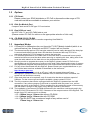
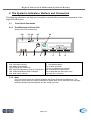
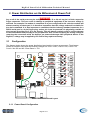
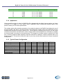
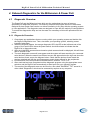
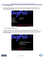
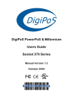
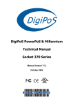
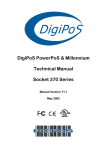
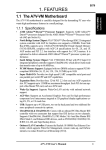
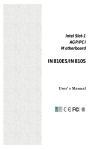
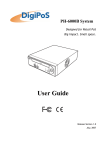
PowerPoS & Millennium
DigiPoS Retail System User's Guide
Socket 370 Series
Manual Ver. 1.1
April 2002
DigiPoS PowerPoS & Millennium Technical Manual
SAFETY INSTRUCTIONS
1.
2.
3.
4.
5.
Always read the safety instructions carefully.
Keep this User’s Manual for future reference.
Keep this equipment away from humidity and dust.
Lay the equipment on a reliable flat surface before setting it up.
The openings on the DigiPoS are for air convection, hence protecting the equipment from
overheating. DO NOT COVER THESE OPENINGS. For a more detailed explanation about
ventilation requirements, please check the on-line documentation available at
http://www.pc-pos.com/
6. Make sure the voltage of the power source (mains) conforms within the permitted range before
connecting the equipment to the power inlet.
7. Place the power cord in such a way that people cannot step on it. Do not place anything over the
power cord.
8. ALWAYS shut down the operating system and disconnect the unit from any power sources before
removing any connections (Keyboard, Mouse, etc..) or opening up the unit to fit additional cards and
or devices.
9. ALWAYS turn off the power switches of the power adapter and the system before connecting the AC
power cord with the power adapter.
10. All cautions and warnings on the equipment should be noted and adhered to.
11. Never pour any liquid into the opening that could damage or cause electrical shock.
12. If any of the following situations arise, have the equipment checked by qualified service personnel:
• The power cord or plug is damaged
• Liquid has penetrated into the DigiPoS
• The equipment has been exposed to moisture
• The DigiPoS is not working well or you can not get it to work according to the User’s
Manual
• The DigiPoS has been dropped and damaged
• The DigiPoS has obvious signs of breakage or physical damage
13. DO NOT LEAVE THIS DigiPoS IN A NON-AIRCONDITIONED ENVIRONMENT WITH A STORAGE
TEMPERATURE ABOVE 60ºC (140ºF) AS IT MAY DAMAGE THE EQUIPMENT.
14. For reasons of safety, gloves should be worn when assembling the DigiPoS after any work has
been carried out.
NOTE
• The technical descriptions and specifications of the Millennium & PowerPoS are subject to
change without notice.
CAUTION
There is a danger of explosion if the CMOS battery is incorrectly replaced. Replace only with
the same or equivalent type of battery. Please Contact you’re nearest PC-PoS office for
further information and or assistance.
FCC Radio Frequency Interference Statement
Page 2 of 2
DigiPoS PowerPoS & Millennium Technical Manual
This equipment has been tested and found to comply with the limits for a class A digital device. These
limits are designed to provide reasonable protection against harmful interference when the equipment is
operated in a commercial environment. This equipment generates, uses and can radiate radio frequency
energy and, if not installed and used in accordance with the instruction manual, may cause harmful
interference to radio communications. Operation of this equipment in a residential area is likely to cause
harmful interference, in which case the user will be required to correct the interference at this own
expense.
Notice
The changes or modifications not expressly approved by the party responsible for compliance could void
the user’s authority to operate the equipment.
Page 3 of 3
DigiPoS PowerPoS & Millennium Technical Manual
USER’S NOTICE
No part of this manual, including the products and software described in it, may be reproduced,
transmitted, transcribed, stored in a retrieval system, or translated into any language in any form or by
any means, except documentation kept by the purchaser for backup purposes, without the express
written permission of PC-PoS.
PC-PoS provides this manual “AS IS” without warranty of any kind, either express or implied, including
but not limited to the implied warranties or conditions of merchantability or fitness for a particular purpose.
In no event shall PC-PoS, its directors, officers, employees or agents be liable for any indirect, special,
incidental, or consequential damages (including damages for loss of profits, loss of business, loss of use
or data, interruption of business and the like), even if PC-PoS has been advised of the possibility of such
damages arising from any defect or error in this manual or product.
Specifications and information contained in this manual are provided for informational use only, and are
subject to change or update at any time without notice, and should not be construed as a commitment by
PC-PoS. PC-PoS assumes no responsibility or liability for any errors or inaccuracies that may appear in
this manual, including the products and software described in it.
Updates to this manual and additional information may be found on the Internet at
http://www.pc-pos.com/
All brand names and registered trademarks mentioned in this manual are the property of their respective
owners.
Page 4 of 4
DigiPoS PowerPoS & Millennium Technical Manual
CONTENTS
1.
INTRODUCTION ................................................................................................................................. 6
1.1
Key Features ...................................................................................................................................................6
1.2
Options.............................................................................................................................................................8
1.2.1
PCI Cards..................................................................................................................................................8
1.2.2
Disk On Module Port................................................................................................................................8
1.2.3
Dual VGA out card...................................................................................................................................8
1.2.4
CD-ROM/ CD-R/ CD-RW .......................................................................................................................8
1.3
Important Notes ..............................................................................................................................................8
1.3.1
If PowerPoS or Millennium does not have the TV-OUT Module installed (which is an optional feature),
the S-terminal and RCA TV output will not function. .............................................................................................8
2.
THE SYSTEM’S INDICATORS, BUTTONS AND CONNECTORS .................................................... 9
2.1
Front Panel Orientation.................................................................................................................................9
2.1.1
The Millennium & Power PoS .................................................................................................................9
2.1.2
Note ..........................................................................................................................................................9
2.2
Rear Panel Orientation ................................................................................................................................10
2.2.1
The Millennium & Power PoS ...............................................................................................................10
2.3
Internal System Orientation ........................................................................................................................10
2.3.1
The Millennium & Power PoS ...............................................................................................................10
3.
POWER DISTRIBUTION ON THE MILLENNIUM & POWER POS.................................................. 11
3.1
Configuration ................................................................................................................................................11
3.1.1
Power Board Configuration....................................................................................................................11
3.1.2
Application .............................................................................................................................................12
3.1.3
Typical Power Configuration .................................................................................................................12
4.
ONBOARD DIAGNOSTICS FOR THE MILLENNIUM & POWER POS ........................................... 13
4.1
Diagnostic Overview.....................................................................................................................................13
4.1.1
Diagnostic Procedure..............................................................................................................................13
4.1.2
Printer Test .............................................................................................................................................14
4.1.3
Customer Display Test ...........................................................................................................................14
4.1.4
Keyboard Test.........................................................................................................................................15
4.1.5
Magnetic Card Test.................................................................................................................................16
4.1.6
Bar Code Scanner Test ...........................................................................................................................17
5.
SETUP OVERVIEW .......................................................................................................................... 18
6.
WARRANTY POLICY ....................................................................................................................... 19
6.1
Limited Warranty.........................................................................................................................................19
Page 5 of 5
DigiPoS PowerPoS & Millennium Technical Manual
6.2
Warranty Return Procedures......................................................................................................................19
1. Introduction
Congratulations on the purchase of your DigiPoS Retail System!
You are now the owner of a state-of-the-art DigiPoS Retail System, a solution that offers enhanced
features, speed, and performance combined with exceptional reliability. It is also a PC that is unrivaled
by other conventional Pentium-686-based PCs within the EPoS industry.
1.1
Key Features
Component
Description
CPU
Supports Socket 370 Intel Celeron / PIII/VIA Cyrix C3 CPUs
CPU CLOCK
266 MHz to 1GHz
MAIN MEMORY
Notebook SO-DIMM X 1 up to 512MB (SDRAM or EDO)
BIOS
Enhanced ACPI 1.0 / PnP / APM / DMI / ESCD / PCI bus 2.1 / OnNow /
DRAM ECC Quick Boot / HW Monitor (LDCM) / I-O Pre-set IRQ / Spread Spectrum /
PC98 compliant
CACHE MEMORY
512KB P.B. SRAM
EXPANSION SLOTS
Riser Card with 3 FREE Slots:
1 x ISA, 2 x PCI and 1 x IDE2 CD-ROM connector
SERIAL PORTS
COM1, COM2, COM3, COM4 (COM3/4 output on riser card).
IRQ & I/O address selection by BIOS (Jumper less).
PARALLEL PORT
One LPT port (SPP / EPP / ECP)
IRQ and address selectable by BIOS
USB
TWO USB ports supporting Windows 95/98/Me/2000/Xp
FDD
1.44MB / 3.5" FDD x 1
ENHANCED PCI IDE
On board PCI Bus Master IDE1/2 controller with Windows utility.
Supports Ultra DMA/66
AGP GRAPHICS
ADAPTER
VIA 8604 AGP with shared memory from 2MB up to 32MB.
Features include:
Support for 4X AGP VGA controller
Support for 3D / 2D Graphics Accelerator
Support for DVD Video Accelerator
Support for VESA DPMS VGA Monitor for Power Management
Direct X, VPE, MPEG2
NT4.0 / 5.0, Windows95/98/Me/2000/Xp utility
APM / ACPI 1.0
Supports VESA DPMS VGA monitor for power management
PC98 compliant
CRT and LCD TMDS output (Optional)
Supports dual monitor output (optional) under Windows 98/Me/2000/Xp
Page 6 of 6
DigiPoS PowerPoS & Millennium Technical Manual
ONBOARD LAN
(10/100Mbs
Auto sensing)
ACPI / NT4.0 / 5.0 (NDIS 5)
NT 4.0 / Win95/98 utility
Remote boot ROM
NT4.0/Win95/98 Utility
PC98 compliant
Enable or disable by BIOS setup (Jumper less)
ONBOARD AUDIO
AC97 CODEC on board
DISK ON CHIP
With DigiPoS EPoS Diagnostics Utility
Component
Description
KEYBOARD PORT
PS/2 type
MOUSE PORT
PS/2 type
FRONT PANEL
Front panel features include:
AC power on/off button
3 LED indicators: Power On/Off, HDD state & LAN state
1.44MB FDD
Door for FDD and Power switch (with key lock)
Slim 24X CD-ROM or CD-R/ CD-RW (optional) drive bay
BACK PANEL
Back panel features include:
VGA CRT 15-pin DSUB connector
COM1/2/3/4 9-pin DSUB output connectors
LPT 25-pin DSUB connector
PS/2 Keyboard & Mouse connectors
LAN RJ-45 output connector
USB1 / USB2 connector
Audio line in / line out, microphone-in
2nd CRT and LCD TMDS output (optional)
TV S-Video and RCA connector output (optional)
THERMAL SOLUTION
One low-noise 50mm fan for power supply and HDD
One low-noise 50mm fan for CPU heat-pipe (water cooling system)
and air tunnel
AC POWER SUPPLY
300W External Power Supply
(UL, CSA, VDE, EMI meets FCC *B*)
AC POWER SOURCE
AC 90V to 264V, 60Hz / 50Hz
CASE DIMENSIONS
11"(W) x 11" (D) x 3" (H) (280 x 280 x 75mm)
(Excluding PSU)
S/W COMPATIBILITY
DOS / OS2 V2.1 / SCO XENIX: V2.3.2 / SCO UNIX V3.2 / NOVELL /
WIN 3.1/95/98/Me/NT4.0/2000/Xp
EXPORT PACKAGING
Each pack measures 36 x 36 x 19cm and weighs 5.5kg net 6.5kg gross
TEMPERATURE
Operating: 0ºC to 40ºC (without HDD up to 50ºC)
Storage: -25ºC to 70ºC
Page 7 of 7
DigiPoS PowerPoS & Millennium Technical Manual
1.2
Options
1.2.1 PCI Cards
Please contact your EPoS distributor or PC-PoS to discuss the wide range of PCI
card add-ons that are available to enhance your solution.
1.2.2 Disk On Module Port
Compact Flash card ATA IDE type I PC card socket
1.2.3 Dual VGA out card
2nd CRT VGA, TV and LCD TMDS add-on card
(Please contact PC-PoS for advice on the appropriate selection of this card)
1.2.4 CD-ROM/ CD-R/ CD-RW
On board PCI Bus Master IDE1/2 controller supporting Ultra DMA/33.
1.3
Important Notes
1.3.1 If PowerPoS or Millennium does not have the TV-OUT Module installed (which is an
optional feature), the S-terminal and RCA TV output will not function.
1.3.2
The thermal transfer pad on CPU heat pipe assembly can be easily damaged if the heat pipe
is removed and refitted several times. We therefore recommend that only PC-PoS or
authorized agents for PC-PoS attempt to remove the heat pipe.
1.3.3 For maximum performance, the cable used for the hard drive is constructed from a special
material and due care must be taken when removing or replacing this item, taking note of the
route the cable takes from the hard drive to the motherboard connector.
1.3.4 Should you wish to upgrade the memory in the DigiPoS, please contact PC-PoS for the
specifications on the correct type of memory to be used. Using inappropriate types of memory
may significantly degrade the performance of your DigiPoS and also render it unserviceable.
1.3.5 For any drivers associated with this DigiPoS, please contact your supplier/distributor or you
can find the latest versions available for download on the Internet at
http://www.pc-pos.com
1.3.6 As the power supply of this unit is an AT type, it will not support Advanced Power
Management (APM) functions. Under Windows 2000, if the APM function is enabled, the
system will not shut down correctly.
1.3.7 If the hard drive has to be replaced, only fit a hard drive that has a maximum speed of
5400rpm. For the correct type and options available, please contact PC-PoS.
1.3.8 The only connectors that can be unplugged while the DigiPoS is powered are the USB
connectors. If any other connector is removed or replaced while the power is on, serious
damage can occur to the DigiPoS. This is considered to be outside the scope of the warranty
and will attract a charge for the repair of any damage caused by this action.
1.3.9 The installation of an internal CD-ROM will determine the maximum card length used in the
32-bit PCI SLOTS located in PCI 1/PCI 2 because of the compact nature of the DigiPoS. The
length of any PCI add-on card is as follows:
1.3.9.1 190mm long x 110mm wide without CD-ROM
1.3.9.2 140mm long x 110mm wide with CD ROM
1.3.9.3 The ISA SLOT has a maximum length of any add-on card of
170mm long x 110mm wide.
Page 8 of 8
DigiPoS PowerPoS & Millennium Technical Manual
2. The System’s Indicators, Buttons and Connectors
The following information will help you to acquaint yourself with the external components of the
DigiPoS Retail System.
2.1
Front Panel Orientation
2.1.1 The Millennium & Power PoS
(Shown with front panel down)
10
1
2
11 12
3
13
4
14
5
1) LED- Power On Indicator
2) LED- LAN Status Indicator
3) LED- HDD Activity Indicator
4) Front Panel & CD ROM Lock
5) LED- DigiPoS Diagnostics Disk On Chip Active
6) LED- Power Distribution Board Voltages
7) LED- FDD Activity Indicator
6
7
8
9
8) FDD Drawer
9) FDD Release Button
10) CD ROM (Optional)
11) LED- CD ROM Activity Indicator
12) CD ROM Drawer Open Button
13) CD ROM Manual Draw Open Catch
14) Power On / Off Switch
2.1.2 Note
The Front Panel Styles are different between the Power PoS and the Millennium. The
diagrams shown here are greatly simplified to enable ease of use and there may be slight
variations between these diagrams and the model you have.
Page 9 of 9
DigiPoS PowerPoS & Millennium Technical Manual
2.2
Rear Panel Orientation
2.2.1 The Millennium & Power PoS
1 2
3
4
5
6
7
8
9
10
11
1)
2)
3)
4)
5)
6)
7)
8)
12 13 14
DC Power Input From PSU
24V Hosiden Connector
Cash Drawer Loop Through Connectors
2.5mm Barrel Connector
16 17 18 19
11)
12)
13)
14)
15)
Parallel Port
COM3 Port
PS/2 Mouse Port
COM4 Port
PS/2 Keyboard Port
16) Microphone In Socket
17) Line In Socket
18) Line Out Socket
19) S-Video Out (Optional)
20) TV Out (Optional)
COM1 Port
COM2 Port
Pulling Knob
Two USB Ports
9) LAN Port
10) Parallel Port
2.3
15
Internal System Orientation
2.3.1 The Millennium & Power PoS
1) Power distribution board
2) Riser Card
3) HDD/FDD sub chassis
4) CD-ROM
Page 10 of 10
20
DigiPoS PowerPoS & Millennium Technical Manual
3. Power Distribution on the Millennium & Power PoS
WARNING
Any or all of the serial ports may be configured for 5, 9, 12 or 24 volt on pin 9 of their respective
D-type connector. This can result in damage to peripheral equipment if the incorrect voltage is
selected. For example if a modem is connected to a port configured for 24 volts the modem will
almost certainly be destroyed. It is therefore imperative that the voltage selected is suitable for
the device attached. It is also important to remember that the industry standard connector for a
RS232 serial port is a 9 pin D-type plug, and as pin 9 can be powered it is physically possible to
short out pin 9 to either pin 5, 8 or the chassis. This will almost certainly result in serious damage
to the motherboard and possibly to the peripheral as well. If either selecting the wrong voltage or
removing the connectors while the devices are powered damages ANY peripheral device or the
DigiPoS, a charge may be applied by PC-PoS for any repairs necessary.
3.1
Configuration
The diagram below shows the power distribution board and the jumper arrangement. The diagram
shows an example setup with the following voltages set: Com1 = 24V, Com2 = 24V, Com3 = 5V,
Com4 = Not Set and the 2.5mm Barrel = 12V.
F1
+ 24V
24
5A
F2
+ 9V
COM 1
12
2A
F3
4A
F4
24
+ 12V
COM 2
12
+ 5V
2A
24
COM 3
12
24
COM 4
12
24
12
5
J1
9
5
J2
9
5
J3
9
5
J4
9
COM 1
COM 2
COM 3
COM 4
J6
5
J5
9
J7
Power Distribution Board Layout
3.1.1 Power Board Configuration
Page 11 of 11
DigiPoS PowerPoS & Millennium Technical Manual
Jumper
J1
J2
J3
J4
J5
Port
COM1
COM2
COM3
COM4
Barrel
Setting
0, 5, 9, 12, 24, Modem
0, 5, 9, 12, 24, Modem
0, 5, 9, 12, 24, Modem
0, 5, 9, 12, 24, Modem
0, 5, 9, 12, 24, Modem
Default Setting
Not set
Not set
Not set
Not set
Not set
3.1.2 Application
Unless specified at time of order, the DigiPoS will be shipped with the default jumper settings, as shown
in section 2.6 on page 12. If you wish to have a particular setup, including the Modem option, then
please contact your PC-PoS representative.
The modem option will permit the connection of an external modem to the DigiPoS and allows the use of
the ring indicator (RI) signal. The Ring Indicator is the signal the modem gives to the DigiPoS to tell the
software that someone is trying to connect to it. The RI signal is normally found on pin 9 of the d-type
connectors and as this is the pin that is used to supply power to the peripherals it is necessary to replace
the internal cable connection to the selected port. For example if a modem option is selected for COM
port 3, then the powered cable assembly would be removed for COM port 3 and be replaced with a non
powered version. This would not affect the other 3 ports, they would remain powered or as per requested
configuration.
3.1.3 Typical Power Configuration
Device
Epson PoS Printer
Epson PoS Display
MSR-512 swipe reader
MS-9540 Voyager
DigiPoS Customer Display
LCD Monitor
External Modem
0
5
9
12
X
X
X
X
X
X
X
X
X
X
X
X
X
X
X
X
X
X
X
X
X
X
Page 12 of 12
24
Modem
X
X
X
X
X
X
X
X
X
DigiPoS PowerPoS & Millennium Technical Manual
4. Onboard Diagnostics for the Millennium & Power PoS
4.1
Diagnostic Overview
The PowerPoS and the Millennium have built onto the motherboard an area of memory
specifically for diagnostic purposes. This memory area and the program stored in it have been
designed so that system tests can be run without interfering in any way with the operating system
or user applications. The diagnostic tests are designed to cope with the majority of configurations.
To access the diagnostics utility and run the tests it is necessary to follow the procedure laid out
below.
4.1.1 Diagnostic Procedure
1. Close down any applications that are running within your operating system and double click
the DigiPoS Diagnostics Icon. Then, shut down your operating system, selecting restart
instead of shut down.
2. When the DigiPoS restarts, the orange diagnostic LED, the LED at the left hand end of the
group of four small LED’s below the power switch, should illuminate to indicate that the
DigiPoS is in diagnostic mode.
3. After the initial BIOS screens have cleared a splash screen should be displayed, this will clear
after a second or two.
4. The main diagnostic screen will now appear and the system will start searching for connected
serial devices. When the search has finished a menu will appear below the logo and show the
serial devices found, as per the diagram below. Check that the devices found match the
devices attached and that the serial parameters match those defined for the peripherals.
5. Exercise each of the test procedures as described in section 4.1.2 to 4.1.6.
6. After each test has been completed exit the diagnostic program using the appropriate menu
selection and the DigiPoS will automatically re-boot back into your operating system.
7. The results of the diagnostic tests can be found in a file called “DIAGRSLT.TXT” stored in a
drive called “Diagnostics” which can be accessed by explorer or my computer.
An Example of a Diagnostic Test Screen
Page 13 of 13
DigiPoS PowerPoS & Millennium Technical Manual
4.1.2 Printer Test
Please note that the Printer test will only work with printers that are Epson ESC/PoS compliant. The
serial scanning software will not reliably detect printers that are not ESC/PoS compliant and therefore
the tests cannot be relied upon.
An Example of a Printer Test
4.1.3 Customer Display Test
Please note that the Customer Display test will only work with displays that are Epson ESC/PoS
compliant, these include all of the Epson displays and the DigiPoS CD-5220 (when set up for ESC/PoS
emulation). Start the test by pressing the numbered key next to the menu entry; this will either be menu
item 1 or menu item 2.
An Example of a Customer Display Test
Page 14 of 14
DigiPoS PowerPoS & Millennium Technical Manual
The display should now start to perform a variety of tests culminating with the following picture.
An Example of a Customer Display
If this picture fails to appear then there is probably something wrong with the display and should be
investigated further by a qualified technician.
4.1.4 Keyboard Test
Due to the almost infinite variations of keyboard layout and key code assignment this facility can only
perform the most basic of tests. The test only allows standard keys, i.e. 0-9 a-z and F1-F10 to be tested.
An Example of a Keyboard Test
On any given PoS keyboard these keys my or may not be present and even if they are present they may
be labeled as stock items or type of transaction, for example the key producing the letter “a” may be
labeled as “Cheque”. The result of this is that pressing any key on the keyboard may well produce
unexpected, but not necessarily incorrect results. Pressing any key 3 times terminates this test.
Page 15 of 15
DigiPoS PowerPoS & Millennium Technical Manual
4.1.5 Magnetic Card Test
The diagnostic software is unable to detect the presence or absence of a magnetic card reader due to
the fact that the majority of card readers only transmit data and do not receive data. Because of this the
test menu will always show a magnetic card reader test even if there is no reader attached. To test a
card reader, select the appropriate menu entry and pass a card through the reader. If the reader is
working then the contents of the data tracks will be displayed on the screen along with a question asking
if the displayed data is correct. The data displayed should be the same as that embossed or printed on
the card. Please note that this test only works with keyboard wedge devices and not serial.
An Example of an MSR Test
The majority of cards will store more data than is visible on the card, this is normal and as long as the
display includes the information on the card then it is relatively safe to assume that the card reader is ok.
If the card fails to read then try another card or a card from a different supplier. If no data has been
received after 10 seconds then the menu will revert to the main test menu. DO NOT swipe cards outside
of the magnetic card test. Swiping cards outside of this area will produce unpredictable results.
Page 16 of 16
DigiPoS PowerPoS & Millennium Technical Manual
4.1.6 Bar Code Scanner Test
The diagnostic software is unable to detect the presence or absence of a bar code scanner due to the
fact that the majority of bar code scanners only transmit data and do not receive data. Because of this
the test menu will always show a bar code scanner test even if there is no reader attached. To test a bar
code scanner select the appropriate entry in the main test menu and within 10 seconds scan a bar code.
Please note that this test only works with key board wedge scanners and will not work with serial
scanners.
An Example of a Bar Code Test
Page 17 of 17
DigiPoS PowerPoS & Millennium Technical Manual
5. Setup Overview
The DigiPoS Retail System contains its own permanently programmed SETUP routing, which allows it to
recognize and utilize the system's hardware. For example, one can set the system to identify hard disk
and floppy disk drive capacity, the type of video being used, and the amount of memory installed. The
BIOS (BASIC Input / Output System) will read this information each time the system boots up.
As setting up the BIOS can be complicated, PC-PoS advises that if any changes to the BIOS are to be
made, only competent qualified computer technicians undertake them. The majority of the settings within
the BIOS are operating system dependant and have been set up in accordance to your systems
configuration. Altering these settings is not advised under any circumstances as any one setting
incorrectly set can drastically alter the performance of your DigiPoS. Should the need arise to change
any of these settings, please contact your nearest PC-PoS office.
Page 18 of 18
DigiPoS PowerPoS & Millennium Technical Manual
6. WARRANTY POLICY
6.1
Limited Warranty
This product is warranted to be free of defects in materials and workings. This warranty period
shall begin from the date of the accompanying invoice and will be in effect for a period of 3
Years.
6.2
Warranty Return Procedures
The customer must call the PC-PoS representative’s technical support department or PC-PoS
directly first so that any primary fault diagnosis can be carried out. If the fault remains, PC-PoS
will issue a Return Authorization form, which must be filled out and returned with the following
information:
1)
2)
3)
4)
5)
6)
7)
Contact Name and Physical Address.
Phone Number including any area or country codes.
Model Number.
Serial Number.
Invoice Number.
Date of Purchase.
Detailed description of the fault.
Failure to provide complete and correct information will result in significant delays in processing
your application for a returns authorization. Once your request has been processed, a Returns
Authorization number will be issued and this must be attached to the goods being returned.
Only at this stage can the goods now be returned. Any merchandise sent for repair without a
valid Returns Authorization number will not be accepted and might incur additional costs. All
freight costs to return the DigiPoS back to PC-PoS are the responsibility of the customer except
where special authorization for freight exemption has been granted by a PC-PoS management
representative.
THE FOLLOWING SHALL VOID WARRANTY
Any unauthorized service, modification, tampering, any damages due to accident, misuse,
abuse and or operation outside of electrical specifications shall void the warranty. This also
includes modification of the specification of the DigiPoS as it was originally supplied including
hard drive, memory, CPU, floppy disk drives, expansion cards and any other additional
equipment not mentioned here specifically.
There will be charges for labor and/or materials for repairs carried out after the warranty period
has expired. Please call your nearest PC-PoS office for a quotation on post warranty service.
Page 19 of 19