1
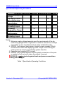
SPROG II User Guide 5 Specification/Operating Conditions Parameter Minimum DC Input supply 10V voltage Vin supply current – not programming Vin supply current – programming Vin supply current – Operating Layout Operating Temperature Range Output Load programming Output Load – Operating Layout Nominal Maximum Units Note 15V V 1 50 mA 300 mA 2 A 3 1 25 °C 250 1 mA 2 A 3 Notes: 1. Minimum supply voltage depends upon the requirements of the de coder being programmed. In general it is safer to use as low a voltage as possible in case of problems with a newly installed decoder. 2. SPROG II will remove track power if output current exceeds 250mA as measured 100ms after applying power. Surge current during de coder power-up may be considerably greater than this. 3. Depends upon required DCC current. 4. SPROG II is protected against reverse polarity connection of the pow er supply but will not work unless the polarity is correct. SPROG II is not protected against track and power connections being interchanged. ! Table 1 Specification/Operating Conditions Version 1.1 December 2007 © Copyright 2007 SPROG DCC