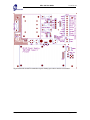
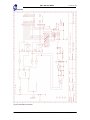
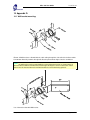
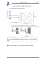
1
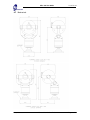
Issue No: 10
Mic1-300 User Guide
User Guide
Forward Vision CCTV.
Mic1-300 Mk2.
& Mic1-400.
Part No. 300-202
Date: 18/07/04
Author: P.G.Dobson 2004
Forward Vision CCTV Limited
Unit 1, Taplins Court,
Church Lane,
Hartley Wintney,
Hants. RG27 8XU.
All Rights Reserved. No part of this document may be reproduced or stored in a retrieval system, or
transmitted in any form or by any means, electronic, mechanical, photocopying, recording or
otherwise without the prior written permission of Forward Vision CCTV Ltd.
Neither Forward Vision CCTV Ltd nor its affiliates shall be liable to the purchaser of this product or
third parties for damages, losses, cost, or expenses incurred by the purchaser or third parties as a
result of: accident, misuse, or abuse of this product or unauthorised modifications, repairs or
alterations to this product, or failure to strictly comply with Forward Vision CCTV Ltd operating and
maintenance instructions.
Last printed 16/08/2004 15:24
Mic1-300User Guide10B.doc
Page 1 of 48
Mic1-300 User Guide
Issue No: 10
Table Of Contents
1
2
3
4
5
6
7
8
9
Revision Record ............................................................................................. 3
Declaration of Conformity............................................................................... 4
Safety Instructions.......................................................................................... 5
3.1
Safety Information.
5
4.1
4.2
4.3
4.4
4.5
4.6
4.7
4.8
Look Angles
Speed
Pre-set Function
Environmental
Size and Weight
Power supply requirements
Mechanical.
Video Performance
6
6
6
6
6
6
7
8
6.1
6.2
6.3
6.4
6.5
6.6
Unpacking the Camera.
Unit Electrical Connections
Earthing the camera.
Lightning protection.
Recommended Electrical connection to the unit
Unit Mechanical mounting
9
9
10
10
10
11
7.2
7.3
7.4
7.5
Power Connections outputs
Mains Connection input.
Video Connection.
Terminal Box indicators.
14
14
14
14
Camera Preset Commands:
26
Functional Specification. ................................................................................ 6
Product Options.............................................................................................. 8
Installation of the Camera. ............................................................................. 9
Forward Vision CCTV camera terminal box. .................................................. 13
Commissioning the Camera using CamSet.................................................... 15
Setting up camera presets with SonySet........................................................ 23
9.1
10
Appendix A. ................................................................................................. 27
11
Appendix B. ................................................................................................. 29
12
13
Figures. ....................................................................................................... 31
Appendix D.................................................................................................. 35
10.1
11.1
11.2
13.1
Connecting either CamSet or SonySet to a Mic1-300 for testing purposes.
27
Types of telemetry connection.
Detailed description of the RS422 / 485 data link via copper connection.
29
29
Special preset codes for other protocols
37
Last printed 16/08/2004 15:24
Mic1-300User Guide10B.doc
Page 2 of 48
Issue No: 10
Mic1-300 User Guide
1 Revision Record
Issue
0.1
0.2
0.3
0.4
0.5
0.6
0.7
0.8
0.9
10.0
Date
05/03/99
18/09/00
16/03/01
20/11/01
05/11/02
17/01/03
12/01/04
18/03/04
12/05/04
08/07/04
Clause No.
Para 9.0
Last printed 16/08/2004 15:24
Revision Details
Draft
First Issue
Second Issue
Third Issue
Clarification of Table in Para 7.0
Appendix D addition.
Update use of CamSet
Inclusion of Tours set-up in CamSet.
Correction to mapped camera presets
General Update for Mic1-300 / 400
Mic1-300User Guide10B.doc
Author
PGD
PGD
PGD
PGD
PGD
PGD
PGD
PGD
PGD
PGD
Page 3 of 48
Mic1-300 User Guide
Issue No: 10
2 Declaration of Conformity.
Manufacturer:
Address:
Forward Vision CCTV Ltd.
Unit 1,
Taplins Court,
Church Lane,
Hartley Wintney,
Hants.
RG27 8XU.
Declares that the product:
Product Name:
Type Name:
Model:
Mic1-400.
Telemetry controlled Camera unit.
300-202.
This unit has been tested and found to comply with the following E.U. directives and specification.
Mechanical Hazards
Safety
EMC directive
98/37/EC.
73/23/EC. Standards EN60950 (UL 1950).
89/336/EC. Standards EN55082-1, EN55022-1.
July 2004.
Peter Dobson
Director, Forward Vision CCTV Ltd.
Last printed 16/08/2004 15:24
Mic1-300User Guide10B.doc
Page 4 of 48
Mic1-300 User Guide
Issue No: 10
3 Safety Instructions.
Please read all of these instructions and save them for future reference. Follow
all warnings and instructions marked on the product.
• Do not install in any other manner than that described in this document.
• Do not back drive the pan or tilt axis of the camera. To do so will damage the
motor drive gear chain and will invalidate the warranty.
• Use only the power sources indicated in this user guide.
• Ensure that the product case is properly earthed. If the product is likely to be
struck by lightning, ensure that earth-bonding connections are made correctly
to the mounting base of the unit (See Para 6.4 of this user guide).
• Ensure that the current rating of the supply cable is adequate for the product.
• There are no user serviceable parts in this product. Any attempt to open the
product casing will void the warranty.
• In situations where there could be a risk of injury, should any part of the
assembly become detached for any reason and fall, normal common sense
safety precautions should be employed. A strong safety chain between the
camera pan shaft and the mounting surface is recommended (See Para 6.6).
3.1
Safety Information.
3.1.1 Warnings, Cautions and Notes.
Warnings
must be followed carefully to avoid bodily harm.
Cautions
must be observed to avoid damage to the product.
Notes
Contain important information and useful tips on the operation of
the product.
Last printed 16/08/2004 15:24
Mic1-300User Guide10B.doc
Page 5 of 48
Mic1-300 User Guide
Issue No: 10
4 Functional Specification.
4.1
Look Angles
Pan 360 Degrees Continuous Rotation.
Tilt is limited to a complete single rotation with non-adjustable internal limits set to operate when the
camera is looking at the base unit. This gives a blind cone angle of 40 Degrees.
4.2
Speed
Variable proportional speed up to a maximum of 90º/sec in both Pan and Tilt. The camera’s current
Zoom setting automatically controls the variable speed sensitivity. This ensures viewable pictures for
all manual movement of the camera.
Minimum pan and tilt speed is approx. 0.75º/sec.
4.3
Pre-set Function
Up to 64 pre-set positions for Pan, tilt and Zoom can be stored within the unit.
Pre-set accuracy is better than 0.08 degrees.
The unit also supports preset tours, which can be stored within the unit with individual delay times per
preset position.
4.4
Environmental
The unit as supplied is (except for the connector) compliant with IP68. As the connector is usually well
protected from the elements, being inside the mounting pole or bracket, this should present no
problem for most applications. Should a fully waterproof connector be required then this can be fitted
on request (please contact Forward Vision CCTV for further details).
4.5
Size and Weight
Camera housing
Overall Height
Swept Width and depth
= 151mm dia.
= 340mm.
= 210mm.
Weight
= 4.5 Kgms.
4.6
Power supply requirements
The unit will run from
Maximum current drawn by the unit
Nominal current draw
Standby mode (for battery use) camera off
Last printed 16/08/2004 15:24
15V ac nominal, or 18V dc nominal.
= 1.4 Amps.
= 406mA.
= 100mA.
Mic1-300User Guide10B.doc
Page 6 of 48
4.7
Mic1-300 User Guide
Issue No: 10
Mic1-300User Guide10B.doc
Page 7 of 48
Mechanical.
Last printed 16/08/2004 15:24
Mic1-300 User Guide
4.8
Issue No: 10
Video Performance
Sony FCB-EX480B Camera. Provides a 1V peak CCIR PAL composite video output comprising of
768 x 494 Pixels on a ¼” CCD chip. NTSC output also available
Note: FCB EX780 also available offering 25:1 optical zoom to a 1/6” CCD chip.
Lens F1.4, f = 4.1 to 73.8mm 1:18 x Optical zoom with a further 1:12 x electronic zoom.
Max optical and electronic zoom combined = x 216.
Telemetry controlled operation of camera functions:
Positive / negative pictures.
AE shutter, iris or gain priority.
Colour balance.
Electronic Shuttering.
Auto / Manual Focus.
20 Character camera title.
Picture effects include: Monochrome, pastel, sepia, solarize, slim or stretch picture modes.
Digital effects include: Mirror, still, flash, lumi and trail modes.
In monochrome the IR filter can be deselected making the camera IR sensitive.
5 Product Options.
The Mic1-300 / 400 unit as supplied is equipped with an M25 captive threaded nut and a 12 way
circular connector on the base of the pan shaft. This enables the unit to be directly mounted to a
25mm conduit by first coupling the connector then fitting to the conduit via the threaded nut.
The camera can be mounted in a number of ways using different mounting bases.
Mounting base 300/026. Provides a screw in base with four off M6 mounting holes on a 4” PCD. This
allows the camera unit to be mounted either from the ceiling or from a floor pedestal. The connector
shell used to connect to the camera unit requires space behind the mounting base of approx. 20mm
deep by 20mm dia.
Note: The canted camera cannot be mounted ball down.
Conduit box 300/032. Provides a means of fitting the base (above) to a flat surface and provides a
standard electrical conduit thread on the sidewall for routing of electrical connections. The 300/032
conduit adaptor provides a termination point in places where it is necessary to run the site cables in
surface mount conduit. The conduit adaptor will then accept the 300/026 base directly.
Connection cable 300-223 with mating connector pre-fitted. 2mtrs long. Suitable for connecting the
camera unit to a terminal box close to the camera.
Connection cable 30-225. with mating connector pre-fitted. 10mtrs long. As above, provides
sufficient cable to route down from the top of a mounting pole to a terminal box mounted conveniently
at the bottom.
Connection cable 30-240. with mating connector pre-fitted. 20mtrs long. As above, provides
sufficient cable to route down from the top of a mounting pole to a terminal box mounted conveniently
at the bottom.
Connection cable 30-245. with mating connector pre-fitted. 25mtrs long. As above, provides
sufficient cable to route down from the top of a mounting pole to a terminal box mounted conveniently
at the bottom.
Terminal & PSU Box 703/240D. Provides all the necessary screw terminal connections to connect
the camera unit to third party cabling. It also contains a suitable 15vAC transformer. The terminal box
provides room for the internal mounting of ancillary function cards e.g. washer drive card or multi
alarm card (which also includes the washer function).
Last printed 16/08/2004 15:24
Mic1-300User Guide10B.doc
Page 8 of 48
Mic1-300 User Guide
Issue No: 10
Note: The multi alarm card also has the washer drive circuit on it as well.
Universal bracket 230. with 25mm thread fixings allows the mounting of the Mic1-300 / 400 unit to a
surface of any angle. The 230 Universal Bracket may also be mounted onto the 300/032 Conduit
Adaptor if surface mounted conduit is being used.
6 Installation of the Camera.
6.1
Unpacking the Camera.
Take care when removing the unit from the packaging to ensure that the unit does not roll off
the working surface (on to your feet!) once removed from the packaging.
Check that the packaging included the following parts:
Mic1-300 or Mic1-400 Camera unit. (Note: Mic1-400 is supplied complete with 4” mounting base as
standard.)
This Installation Manual.
Optional equipment will be supplied as per customers order. If the 300-026 is supplied it will be prefitted to the base of the camera unit.
6.2
Unit Electrical Connections
All connections to the unit are provided through the single 12 way connector mounted in the centre of
the 25mm unit mounting thread.
Unit Connections are as follows:
Connector Pin
A
B
C
D
E
F
Signal Name
Video Output.
Video Return.
Tamper Switch.
Tamper Switch return.
Washer drive return.
Washer drive.
G
H
J
Full Duplex Tx A.
Full Duplex Tx B.
Full Duplex Rx A.
Half Duplex Tx/Rx A.
Full Duplex Rx B.
Half Duplex Tx/Rx B.
Power input 1.
Power input 2.
K
L
M
Description.
Output to control room
Connection C to D will provide an alarm to the control
room via telemetry.
TTL output used to drive relay in 703/240D with wash
option.
Telemetry Output RS 485.
Telemetry Output.RS485.
Telemetry I/O to RS485.
Telemetry I/O to RS485.
Low volt AC or DC power input.
Low volt AC or DC power input.
Video output signal conforms to CCIR PAL 1V Composite format. (NTSC format is available on
request).
Last printed 16/08/2004 15:24
Mic1-300User Guide10B.doc
Page 9 of 48
Mic1-300 User Guide
Issue No: 10
Telemetry signals all conform to the RS485 / RS422 standard.
The unit continuously monitors incoming telemetry whether in full or half duplex mode.
In full duplex mode, the Tx pins are tri-state except during transmission times. This may cause
problems when interfacing to some Fibre Optical converter units. Check out the Commissioning notes
for ways of overcoming these problems. Appendix B.
In 2 wire Half Duplex mode (RS485), the Rx Pins are used to transmit messages when called to do
so.
6.3
Earthing the camera.
The camera and camera housing are electrically isolated so the housing should be safety earthed
regardless. This safety earth should be a bonding connection to the camera’s outside case. E.g. one
of the securing screws used for bolting the camera down.
The camera 0v is via the video return Pin B on the connector or (0v) wire pin D on the 12 way
connector.
The Camera should be earthed at one point only to prevent earth loops and thus hum bars appearing
on the camera picture in the control room.
If the system is copper throughout and the camera pictures are fed back to the control room via
coaxial copper cable, then the camera should be earthed at the video termination point in the control
room and nowhere else.
If the video is transmitted back to the control room via some non electrical connecting medium, fibre
optic cable or radio, microwave link, then the camera should be earthed at the transmitter point in the
cable termination box next to the camera unit.
If dual earthing cannot be avoided then a video isolation transformer should be fitted between the two
earths to prevent earth currents flowing.
6.4
Lightning protection.
If the camera is fitted in a high exposed place then consideration should be given to lightning
protection. The construction of the housing itself is very capable of coping with secondary strikes and
no damage to the internal electronics or camera should result if correct lighting protection is applied.
A good earth bonding connection to the case itself will provide protection against damage from
secondary strikes. Where there is a risk of a primary strike hitting the camera housing directly it is
recommended that a separate lightning conductor be fitted within 0.5 Mtrs of the camera and at least
1.5 Mtrs higher than the camera.
6.5
Recommended Electrical connection to the unit
Forward Vision CCTV supplies a purpose built composite cable for use with the camera. These cables
are pre-made with a 12 way connector fitted to them. The standard colour coding used in these cables
is as shown below:
Mic1-300 / 400
Connector Pin
A
B
C
Last printed 16/08/2004 15:24
Signal Name
Video Output
Video Return
Tamper Sw
Cable Wire
colour
Coax core
Coax screen
Black
Mic1-300User Guide10B.doc
Page 10 of 48
Mic1-300 User Guide
D
E
F
G
H
J
K
L
M
Tamper Sw Rtn
Washer drive Rtn
Washer drive
Full Duplex Tx A.
Full Duplex Tx B.
Full Duplex Rx A.
Half Duplex Tx/Rx A.
Full Duplex Rx B.
Half Duplex Tx/Rx B.
Power input 1.
Power input 2.
Issue No: 10
Brown
Grey
Orange
Blue
Violet
Yellow
White
Red
Green
Four different lengths of cable are available:
2 Mtrs
10 Mtrs
20 Mtrs
25 Mtrs
part No: 300-223.
part No: 300-225.
part No: 300-240.
part No: 300-245.
Use of the composite cable for distances in excess of 25 Mtrs between the camera and the power
supply is not recommended. This is because of the volt drop across the power wires to the camera.
If a longer distance is required FV-CCTV recommend the use of a short 2 Mtr composite cable to a
local junction box where telemetry, video and power can be broken out into separate cables. From
this point on back to the power supply heavy gauge wire can be used for the two power cores (red
and Green). The max loop resistance permissible in the cable for guaranteed operation of the camera
under all conditions is 2.5 Ohms.
6.6
Unit Mechanical mounting
The upright unit can be mounted either way up with the camera ball up or down.
The canted unit is designed only to be mounted ball up, the tilt limits for the canted unit prevent it
from working properly if mounted ball down.
Do not manually back drive the pan or tilt axis by hand. Back driving may strip
teeth off the internal gears and in so doing will void the warranty.
During commissioning the unit will be turned in tilt to set the picture to be the correct way up.
Note: There are no internal adjustments required to set the picture to be the correct way up.
The unit can be mounted on the 4”PCB mounting block supplied, or can be mounted on to a series of
tailor made mounting brackets made by Forward Vision CCTV. The thread used conforms to the
standard electrical conduit thread found on 25mm electrical conduit tubing.
M6 Stainless steel nuts, bolts and washers should be used to secure the base to the mounting
surface. Ensure that the mating 12 pin connector is fitted home properly in the camera integral plug
(usually requiring approx. two and a half turns of the socket threaded ring to fasten the two halves of
the connectors together properly).
Caution
To prevent water penetrating the mounting threads and getting inside the camera base unit, the
Last printed 16/08/2004 15:24
Mic1-300User Guide10B.doc
Page 11 of 48
Mic1-300 User Guide
Issue No: 10
25mm thread should be sealed at final installation using PTFE tape. Alternatively a suitable sealant
may be liberally applied to the thread prior to final tightening.
Note: Any water getting into the connector is liable to cause corrosion to the connector pins leading to
unreliable operation of the camera unit.
When finally assembled ensure that the 25mm conduit thread nut on the bottom of the camera is done
up tight (approx. four turns from start of thread engagement). Also ensure that the 4off M6 screws are
securely tightened.
If the Forward Vision CCTV Ltd terminal box is not used, ensure that the supply to the camera is
correctly fused. An in line 1.5A quick blow fuse is appropriate. For details of Forward Vision’s terminal
box and it’s installation, see below.
Note: The Mic1-400 now comes with a security
attachment point as standard. This should be
attached to a safety chain in turn attached to a
secure part of the structure. This ensures that
even when the camera is un-mounted from the
base unit (by removing the four M8 fixing
screws) the camera is still captive until the chain
link is removed.
Last printed 16/08/2004 15:24
Mic1-300User Guide10B.doc
Page 12 of 48
Issue No: 10
Mic1-300 User Guide
7 Forward Vision CCTV camera terminal box.
Product No
703/240D for 240v AC input.
703/115D for 115v AC input.
702/24D for 24v AC input.
702/12D for 12v or 24v DC input for battery operation.
This terminal box (shown in figure 5). Provides all the support functions for connecting the camera to
third party equipment. It comprises of:
A weather resistant (IP55) plastic box fitted with four cable glands.
A power supply for the MIC1-300 / 400 camera.
A second isolated power supply for driving various option cards. E.g. Washer drive card, 8 channel
alarm input card (which includes the washer drive circuit).
Screw termination of all cable into and out of the box.
Correct video termination for the camera coaxial cable.
Earth isolation and termination within the unit to correctly control Video earthing and thus prevent
Earth loop.
The terminal box schematic is shown in figure 6.
7.1.1 Connection between the camera and the terminal box.
Via the composite cable is as per the table below:
Mic1-300 / 400 base
connector pin
Numbers.
L
M
K
J
B
G
H
A
B
C
F
MIC1-300 / 400
Composite cable Wire
colour
Red
Green
White
Yellow
Drain Wire
Blue
Violet
Coax Core
Coax Screen
Black
Orange
D
E
Brown
Grey
Function
AC supply
AC supply return
Rx B
Rx A
Gnd
Tx A
Tx B
Video
Video Return
Tamper Switch
Wash
Terminal
Box
Connector
HD3-1
HD3-2
HD3-3
HD3-4
HD3-5
HD3-6
HD3-7
HD3-8
HD3-9
HD3-10
HD3-11
Terminal
box ID
marking.
15v AC
15v AC
RXB
RXA
GND
TXA
TXB
VIDEO
GND
Tamp Sw
Wash
0v rtn Tamp Sw
0v rtn Wash
HD6-1
HD6-2
0v
0v
7.1.2 Telemetry Connections
The terminal box can be used as a distribution point for telemetry connections and HD5 and HD4 are
connected directly to HD3 on the PCB. This allows connections from the camera cable to be fed back
to the control room through a number of different types of connection.
HD5 allows connection of the site telemetry cable to be terminated via screw terminal connections.
HD4 allows the site cable to be terminated in crimp joints and then be connected to the crimp header
connector. HD4 is particularly useful for use during commissioning the camera as it allows rapid
connection and disconnection of a test cable connected in turn to a /PC running the camera set up
and commissioning programme CamSet
HD3 is the connector for the camera composite cable.
Last printed 16/08/2004 15:24
Mic1-300User Guide10B.doc
Page 13 of 48
Issue No: 10
Mic1-300 User Guide
Telemetry Signal Name
RXB
RXA
GND
TXA
TXB
7.2
HD3
Pin 3
Pin 4
Pin 5
Pin 6
Pin 7
HD4
Pin 1
Pin 2
Pin 3
Pin 4
Pin 5
HD5
Pin 1
Pin 2
Pin 3
Pin 4
Pin 5
Power Connections outputs
15vAC power is available from the camera terminal box via HD3 pins 1 and 2 identified as 15V AC.
This is specifically to drive a single Mic1-300 / 400 camera unit.
12v DC power is generated by a second Power supply on the PCB which is fed to CN2 to drive the
ancillary cards that can be fitted to the power supply, e.g. washer drive card and 8 channel alarm
card.
Max current is limited to approx. 600mA.
7.3
Mains Connection input.
Mains to the terminal box should be connected to HD1 as follows:
Live
Neutral
Earth
HD1-1
HD1-2
HD1-3
The operational voltage of the 703 series power supply is set by the transformer type fitted to the
power supply. There are not transformer jumper links (as on the former 702 PSUs) to set primary
input voltage.
If there are no other connections of the camera 0v to earth, via a locally connected fibre interface unit
or via a video Opto transmission system or some other third party equipment, then the EARTH LINK
situated between HD1 and FS3 should be left intact. If there are other paths between 0v and mains
earth then the earth link on the power supply should be cut.
7.4
Video Connection.
Video from the camera coax cable should be terminated on HD3 at pin 8 for Video and pin 9 for Video
screen. The tin copper wire VIDEO LINK is fitted during manufacture and should always be in place.
7.5
Terminal Box indicators.
LED1 and LED2 when lit show that 15v AC is available from the power supply. There is no indication
of the operation of the Telemetry lines as this would increase the load on these lines reducing the
number of cameras that can be driven by a single telemetry spur.
Last printed 16/08/2004 15:24
Mic1-300User Guide10B.doc
Page 14 of 48
Issue No: 10
Mic1-300 User Guide
8 Commissioning the Camera using CamSet.
Before applying power to the camera check that all connections are correct. Apply power to the
camera and ensure that the Red LED visible through the front window of the camera is blinking at a
steady rate of approximately one flash every two seconds (Very difficult to see). If the LED is flashing
more rapidly then the camera has not initialised properly and it should powered down and powered up
again.
Note: To find the LED, look through the front window and ensure that the camera is the correct way
up (wiper at the top if fitted). Look down through the window from above the camera at an acute angle
almost over the top of the camera. The Red LED will be seen in the centre of the window at the
bottom.
From this point on, the best way to test the operation of the camera is to use the freely available
programme called CamSet running from a /PC.
This programme is only 100K bites long and will run on any /PC with any Windows operating system.
To ensure correct operation the following files should be loaded off the main C: directory into the
directory e.g. C:/WinCam:
Camset50.exe
MSCOMM32.OCX
The main programme is updated regularly so version beyond CamSet 50 may be available.
When opened the CamSet screen will show as follows:
Firstly to get rid of the red banner,
the Serial port must be selected.
For a notebook this can only
generally be “Comm 1”. This should
be selected with the mouse.
Alternatively for notebooks without
a serial Comm port, a USB to
RS232 adaptor can be used in
which case the Comm port selected
must be that mapped by windows
for the USB to RS232 port (usually
Comm3 or Comm4).
Once selected the programme is
ready to receive messages from the
camera.
A camera power on reset should
put a start up message in the
thirteen text box windows in the top
left of the programme panel (Boot
up message and addressing). The
address of the camera detected during boot up will be automatically loaded into the Current Address:
box
Last printed 16/08/2004 15:24
Mic1-300User Guide10B.doc
Page 15 of 48
Issue No: 10
Mic1-300 User Guide
At switch on, the camera goes
through an initialisation routine.
Whilst doing so, it sends out ASCII
readable messages on the RS422 /
RS485 telemetry link. It also
displays on Video a start up text
message for 1-2 seconds
identifying the camera address and
software version No. loaded into the
camera.
The text on screen message
appear in red and looks similar to:
CAM 1 SW 22AUG120GW
Where “CAM 1” is the current
address of the camera.
The message sent out via telemetry
looks as follows and will appear in
the thirteen text windows in the top
left of the CamSet programme screen (called Boot up message and Addressing):
ID is:1
Serial No 1160
MICky 300 Model 5A
Date 15/02/3
Software Version: 22AUG120GW
Multi alarms
Sector captions
Privacy
Camera Initialised
Camera OK
Where = any character (these are binary characters and will not be understood by the ASCII
reader).
ID = Camera address.
Serial No = control card serial No.
Model = build standard of control card.
Date = programming date of control card.
Receiving the above message shows that out bound telemetry from the camera has correctly reached
the telemetry point being monitored and also allows the camera address to be checked.
CamSet will automatically set the camera address in the “Current Address” box. Once an address
appears in this box then camera commands may be sent out via CamSet to that camera.
All “Preset and camera commands” function boxes on the CamSet programme should be selfexplanatory.
To make the camera move the “SPEED” box is preset to a value of 50 (Max speed = 255 min speed
=1).
The “Comms. Testing” Panel to the right of the programme screen is very useful for testing Bit Error
rates. Pressing “TEST” with no tick boxes selected will send 255 test messages to the camera and
should result in:
Last printed 16/08/2004 15:24
Mic1-300User Guide10B.doc
Page 16 of 48
Mic1-300 User Guide
Issue No: 10
Tests = 255
Passes = 255
Failures = 0
Time outs = 0
Any failures indicate corruption of test messages sent back by the camera. Any Time outs indicate no
messages were sent back by the camera at all.
Using the “long test” tick box will send 10,000 test messages, this will take several minutes to
complete.
Use the “1 sec timeout” box when telemetry is switched through a multi-channel hub and channel
switching times are required to allow the hub to correctly switch to the correct channel.
If there is doubt about communications with the Sony FCB 480 camera inside the Mic1-300 / 400 then
ticking the “cam comms” box will send through test messages to the FCB camera module itself inside
the Mic1-300 / 400.
Use the “DETECT” button to map all cameras currently connected to the CamSet programme. This
process will also list the software version at each camera address loaded into the camera. If non
ASCII characters are seen for the software version No, this indicates that there is a duplication of the
camera address on the network with the address that produces the corrupted response.
To Change the address of a camera on the network, firstly ensure that either the address being
changed from is unique or ensure that the camera whose address is being changed is the only one
connected to the CamSet programme. Set in the “NEW Address” window the address to which the
camera is to be changed. Then select the “Set Camera Address” button. To check that the camera
address has indeed changed, either power down and re-power the camera or change the “Current
Address” window to the address just selected and select the “RESET CAMERA” button. Either action
should result in a new start up message and a new 1-2 sec ID message on the Video picture
reflecting the new address just set into the camera. (For cameras built before the year 2000 the set
new address pre2000 button must be used to change camera address).
Pot Test button. This allows the operation of the camera to be tested in real time. This function only
works if the camera is used in Duplex mode. Selecting Pot test will generate a graph as shown
below:
The red trace represents the Pan
position and is driven by the readout
for PAN 3304 under the Pan Left
button. The green trace represents
the power drawn by the Pan axis
servo to make the motor move at the
required speed. The actual power
being shown by the Pan PWM 53.
The blue trace represents the Tilt
position and is driven by the readout
for TILT 2789 under the Tilt Up
button. The Violet trace represents
the power drawn by the Tilt axis
servo to make the motor move at the
required speed. The actual power being shown by the Tilt PWM 32.
The Pot Checker is useful for looking at the servo performance of the camera both for manual move
commands and for presets (1 and 2 only are made available on this screen).
explained.
Last printed 16/08/2004 15:24
Exec Camera Preset allows any one of the preloaded camera module
preset to be executed. These presets are mapped to presets 240 to
249 as per page 19 where the use of the SonySet programme is
Mic1-300User Guide10B.doc
Page 17 of 48
Mic1-300 User Guide
Issue No: 10
Goto and Learn presets are allowed for only on presets 1 to 10 for this
test software. Clicking the numeric button to the right of the goto and
learn buttons will sequentially select the next preset mode.
The blank window under the Learn Preset button allows any Learn
Preset or Goto Preset command to be execute. Simply load the preset
number required in the blank window then select the appropriate preset
button. This mechanism allows any of the special function presets to be executed. See Appendix C for
a complete list of special preset codes.
Pressing the TOURS button produces the sub screen to the left. This allows simple
tours to be set up from CamSet. Dwell time is in seconds. Don’t forget to store the
tour to transfer the details of the tour to the camera Flash memory.
Auto tour on/off allows the tour to start if no manual move commands for this camera
are received over a 5 minute period.
Pressing the SoftStops and Dwell zones button produces the red sub-screen, on the
left:
Softstop defines a rectangular area beyond which the camera cannot go in either pan
or tilt.
Dwell Zone defines a rectangular area in which the camera cannot come to rest but
continues to move in the direction last selected until the boundary is reached.
If for any reason a soft stop or non dwell zone gets partly set the result will be that the
camera can only move in one direction. For example left, but not right. Or up, but not
down. If this happens clearing the softstops and dwell zone will resolve this problem.
Using the Setups Button.
When the Setups button is selected the sub window shown on the left is
opened. This provides access to a number of features that can be switched
on or off by telemetry.
WashWipe On/Off. If selected to On, a wash preset position can be learned
by pointing the camera at the washer nozzle and setting Wash position.
When the Wash button is pressed the camera remembers its current
position, moves to the washer nozzle position and starts the washer and
wiper. Whilst the washer button remains depressed, the washer and wiper
continue to run. On release of the wash button the washer stops and the
camera returns to its previous view. After a further two wipes the wiper stops
too.
Auto Alarm On/Off. Operates as per the WashWipe On/Off. On all Mic1300 / 400s a single tamper switch input is supported. With Auto Alarm
selected on and an alarm position learned, the camera will move to the
Last printed 16/08/2004 15:24
Mic1-300User Guide10B.doc
Page 18 of 48
Issue No: 10
Mic1-300 User Guide
alarm position when the tamper switch is operated. If the Auto Alarm is selected to off, the camera still
reports the status of the alarm bit to the control system but the camera does nothing else in response
to the tamper switch input.
Multi Alarm On/Off. The Multi Alarm facility is used in conjunction with the Multi Alarm Setup window
and can only be used if the 8 or 10 channel alarm scan card is fitted to the power supply box. Or if the
Mic1-400 caries IR illuminators and a special IR PSU. If the multi alarm card is not fitted the camera
must be set to Multi Alarm off to prevent inconsistent operation of the camera.
The numeric buttons 1 to 12 allow for the learning of alarm presets positions for each of the alarm
channels, normally 1 to 8 but 9 to 12 have been included for future designs. To make the camera go
to these presets when the alarm is activated, both the Auto Alarm On and Multi Alarm On must be
selected. The alarm scan card fitted in the power supply has on it two relays for alarm status output
and additionally a relay to drive a washer pump.
The relay operation is controlled as follows:
Any alarm activates relay
Relay closes on alarm
√
√
Only alarms shown activate relay
Relay opens on alarm
The relay alarm rearm time is controlled by the four radio buttons. Times
shown are in seconds.
Once the relay operation has been defined as above the Set relays box must
be selected to load the relay status into the Mic1-300 / 400 camera.
Other functions:
Digital Zoom On/Off sets the availability of Digital zoom permanently.
This function can only be changed from this point.
Auto Flip On/Off allows the camera to pan 180 degrees when mounted
ball down and the target being tracked passes directly under the
camera.
Note: It does take 2 seconds for the camera to slew 180 degrees so be
aware of this time delay during the operation of this function.
AutoHome. This function allows the camera either to go to preset 1 or to restart a tour (sequence) if
the camera receives no commands to move from the operator for a period of 5 mins.
Min Int Spd. This parameter limits the camera to a minimum
frame integration (shutter speed) rate
regardless of lighting conditions. This prevents the camera
going down to a frame rate that is too low for the application
the camera is being used in. Values set in the box represent
the following settings:
Last printed 16/08/2004 15:24
Min Int Spd value
Mic1-300User Guide10B.doc
06
05
04
03
02
01
00
actual minimum
frame rate.
50
25
12
6
3
2
1
Page 19 of 48
Mic1-300 User Guide
Max Gain Lvl. This parameter sets the maximum gain the
camera reaches before frame integration (lower shutter)
speed starts to apply
Min Gain Lvl
value
0F
0E
0D
0C
0B
0A
09
08
Issue No: 10
actual minimum
gain level.
28 db
26 db
24 db
22 db
20 db
18 db
16 db
14 db
AutoLowlight On/Off. Under low light conditions the camera will automatically go into frame
integration mode if this is set to On. Under these conditions the camera will return the best picture it
can for the lighting conditions prevailing. But if light levels are very low then the frame rate can be as
low as 3 frames a second. This makes movement through the cameras field of view very jerky.
Auto IR On/Off. When the Camera is fitted with IR lamps they will switch on and off automatically if
selected as the light levels fall and rise. Unlike other IR illuminators this unit does not use a light
sensor but uses the camera exposure settings to determine the light levels.
Note: AutoLowlight and Auto IR cannot both be selected on as this causes instability in the camera.
This will result in the IR illuminators cycling on and off.
Default Presets. The 64 off Pan/Tilt/Zoom presets can be set to default mid range values should the
camera be found to be responding erratically to preset positions. This can happen if a preset position
has been loaded by the control system that is outside the normal preset working range. The two
numeric boxes can be used to set the lower and upper limits of the preset range that is defaulted if not
all 64 presets need to be reset.
Other sub-screen:
These three buttons open up further sub screens with
additional functions.
780 setup.
This sub screen was set up to help with the Sony FCB-EX780 camera module
when fitted to the Mic1-300 / 400 camera. As with hand held video cameras this
module has a lens stabilisation system Anti shake ON/OFF, which can be
activated by telemetry. It is particularly good at knocking out high frequency
vibrations.
Auto IR ON/OFF and Auto Integration ON/OFF These commands go directly
to the 780 module unlike the functions under Setups. Which correctly adjusts
the 480 camera module and control card operation.
LENS RECALIBRATION. This function is more specific to the Sony FCB-470
camera module. This was replaced by the 480 module in March 2003 onwards.
The 470 module uses stepper motors to operate the zoom and focus drive. It is
possible for the stepper motor position to become different to the position
reported by the camera software. When this happens the focus tracking with
zoom becomes very poor resulting in out of focus pictures. If the RECAL Now
button is selected then the camera will resynchronise the position of the stepper
motor with that recorded in the camera software. This should bring everything
back into focus at all zoom settings. If the problems persist the camera can be
made to automatically recalibrate the lens after a fixed Period set in days and
only after a period of Inactivity telemetry, i.e. no operator is driving the camera.
Last printed 16/08/2004 15:24
Mic1-300User Guide10B.doc
Page 20 of 48
Mic1-300 User Guide
Issue No: 10
Privacy Mask setup.
This sub window only works when the Synectics 3D Video privacy card is
fitted within the camera.
A Mask hides the view in single pixels, which can be either drawn into the
view, pixel at a time, or as blocks covering the whole view.
The mask pixels can be set in a variety of patterns or styles, some of which
can be semi-transparent.
There can be an infinite number of pixels set in any shape.
The masks work best for objects near the horizontal rather than in the sky
or at the bottom of the pole.
The simplest way to set a mask is to zoom in until the object to be masked
just fills the screen. Then set Mask whole screen.
To delete an area of masking, press Clear Whole Screen. Any mask pixels in the current view will be
deleted.
The set individual pixels, press Set Mask Pixel or Clear Mask Pixel.
To make drawing pixels easier, you can switch on a crosshair cursor by pressing Crosshair On.
To change the mask style, make sure the crosshair is on then press Show Mask Style. You should
see a small rectangle appear on the right of the crosshair. Pressing Set Mask Type will step through
all the different mask types.
All Masks can be temporarily removed by pressing Masks Off and replaced with Masks On.
The Privacy card can also be calibrated remotely via the telemetry using the Camset Program.
CALIBRATION
NOTE: THAT CALIBRATION IS NORMALLY CARRIED OUT AT MANUFACTURE AND SHOULD
NOT NORMALLY BE REQUIRED ON SITE.
If a camera is to be installed upside-down, the privacy card has to be set accordingly. To set the
camera orientation, press the appropriate button:
90 UP
90 INV
45
90 Degree upright
90 Degree inverted
45 Degree
The best mask shape to use for calibration is a vertical bar. To draw one, set the camera tilting at a
slow speed and set a series of pixels with the Set Mask Pixel button. It’s best to draw the bar over
some vertical feature such as the edge of a building so that any alignment errors can be seen.
Pan the camera from side to side and check that the vertical bar stays aligned with the background
target.
Last printed 16/08/2004 15:24
Mic1-300User Guide10B.doc
Page 21 of 48
Mic1-300 User Guide
Issue No: 10
If the mask fails to track with the camera when panning, one of the following codes can be entered to
set the alignment:
11
11
11
11
11
1D
1E
1F
20
21
This is the default setting
If the mask appears to bend too much when tilting, one of the following codes can be entered:
13
13
13
13
13
1E
1F
20
21
22
This is the default setting
If the privacy masks tend to tilt inwards too much, set up a vertical bar mask in the centre of the
screen, tilt the camera so that it is horizontal and then pan so that the bar is at the far edge of the
screen. The bar should remain vertical, if it tilts over adjust the following parameter:
03
03
03
03
03
08
09
0A
0B
0C
If the mask appears to drift off centre when zooming in, zoom out and line up the crosshairs with a
target. Set a single pixel and then zoom in. When the pixel has drifted to the edge of the screen, use
the small arrow buttons at the bottom of the Privacy Mask Setup page to move the pixel back into the
middle of the screen.
Finally, if the privacy mask size does not track with zoom, set the following parameters:
1C
1B
1A
19
18
17
16
6F
77
77
7A
85
8D
80
If the Privacy mask appears to track in the wrong direction (images goes left, masks go right) set the
following codes:
08
08
06
07
Inverted
Upright
Once complete, press the SAVE SETTING button to store the setup.
Last printed 16/08/2004 15:24
Mic1-300User Guide10B.doc
Page 22 of 48
Mic1-300 User Guide
Issue No: 10
Captions.
The operation of this sub-screen is self explanatory. Only a single line of
text can be input and a maximum of 20 characters can be input.
The Set/Clear Captions toggles the appearance of captions on the camera
video. It is not possible to tell which way the toggle is set except by
inspecting for on screen text.
Typing in text in the top window followed by selecting the Set Caption
button will upload the test to the camera.
The 8 off radio buttons select where the caption appears on the Video
picture. Bottom Right is not allowed.
Set All Preset Captions will set what ever text is set for the base camera
and will then add the preset number to each caption so that each preset
has a different caption associated with it.
Blank Preset Captions blanks all captions for all 64 preset positions.
NOTE: Warning:
The cam baud toggle button causes the camera to change from its
default operating baud rate of 9600 to 4800. Having selected this button,
all comms to the camera will be lost until CamSet is reset to 4800 baud. Then communications will be
re-established. The cam baud toggle button can then be selected again to return the camera to 9600
baud. CamSet must also be returned to 9600 baud to allow operation to continue.
Interface control.
In conjunction with an appropriate RS232 to RS485 / RS422 adaptor
these radio buttons control the way CamSet communicates with the
camera. The changes are active directly on selection. See Appendix
A, Connecting CamSet to set up different adaptors for operation with the CamSet Programme.
Forward Vision CCTV Ltd also provide their own front-end control system for use with this camera.
The software runs on an IBM compatible /PC and is called WinCam. Further details on this product
are available on request.
9 Setting up camera presets with SonySet.
On the Mic1-300 / 400 presets there are 255 presets available. Presets1 to 64 are for Pan, Tilt, Zoom
and Focus (if manual focus is selected). Other presets above this range are used to operate special
features of the Mic1-300 / 400 that are not available to controllers that do not have the full protocol
support. Presets 140 to 149 are allocated to camera functions only and can be used to set the camera
in to different modes of operation such as Frame integration, colour balance correction and other
functions supported by the Sony FCB480 module camera.
Last printed 16/08/2004 15:24
Mic1-300User Guide10B.doc
Page 23 of 48
Mic1-300 User Guide
Issue No: 10
If these presets are not accessible via the main control systems then Forward Vision CCTV has a
small freely available IBM /PC compatible programme called SonySet that allows these camera
presets to be set up and tested.
As with CamSet it requires a number of support files and all these files should be loaded into a
directory called C:\WinCam.
To make the programme run the following files should appear in this directory:
SonySet10.exe
MSCOMM32.OCX
Sonysetdefault.txt
SonySet is continually being updated and as a result
programmes later than Sonyset10 may now be
available.
Running the programme should open up a window
as shown below:
As with CamSet the serial port must be selected to
remove the red banner. For a notebook this will
normally be Comm1.
Connection to the camera is identical to that of
CamSet using an RS 232 to RS422 adaptor. See
Connecting CamSet Appendix.
Once the Comm port has been selected then the
programme window will be as follows:
The programme defaults address 1 for the camera; if
another camera address is in use then the address
box must be changed.
button will allow preset 149 to be altered.
Programme operation can be tested by selecting the
“GET Preset from Camera” button. This will down
load from the camera the preset loaded for Preset 1
(actually Preset 140), likewise preset 10 in the top
The structure of the camera presets is such that up to ten commands per preset can be sent to the
camera. The command sequence is terminated by the END command.
The total number of commands available to the camera is 122. The commands available can be seen
by opening up the command window using the arrow key to the right of the window, thus:
Last printed 16/08/2004 15:24
Mic1-300User Guide10B.doc
Page 24 of 48
Mic1-300 User Guide
Issue No: 10
Any one of the commands can then be selected
into that command window. Each command
window can be set up to a different command if
required. There is no validity testing of this
process so it is possible to set up inappropriate
command sequences. Care should be exercised
when modifying the command structures.
Command structure can then be tested using the
”Execute this preset” button. Modified
commands must be stored to the camera before
they take effect using the “Set preset in camera”
button. Once a camera has been set up with
presets, all presets loaded can be saved to disk
for reloading into other cameras if required.
If things get out of control then the defaultsetup.txt setting can be reloaded into the Mic1-300 / 400
using the “Load all presets from Disk” button.
At manufacture the camera is preloaded with the
defaultsetup.txt Camera presets:
These provide the following camera functions:
Preset 1, (240) Back light compensation on.
Preset 2, (241) Back light compensation off.
Preset 3, (242) White balance Manual,
Red gain set: 64, blue gain: set 192.
Preset 4, (243) White balance outdoor.
Preset 5, (244) exposure: shutter priority, shutter: set 3
Preset 6, (245) exposure: shutter priority, shutter: set 2
Preset 7, (246) exposure: shutter priority, shutter: set 1
Preset 8, (247) exposure: shutter priority, shutter: set 0
Preset 9, (248) exposure: auto
Preset 10, (249) on screen data: off, exposure: auto,
White balance: outdoor, Backlight: off
to normal).
Attempts to correct for sodium lighting.
Frame integration mode 25 frames / Sec.
Frame integration mode 12 frames / Sec.
Frame integration mode 6 frames / Sec.
Frame integration mode 3 frames / Sec.
General camera reset (puts everything back
This is a list of all the possible commands. You can arrange 10 presets with 10 of the following
commands in each. Presets are recalled with standard Goto Preset commands. Camera preset 1 is
preset 240; camera preset 2 is preset 241 etc, etc.
Last printed 16/08/2004 15:24
Mic1-300User Guide10B.doc
Page 25 of 48
Mic1-300 User Guide
9.1
Issue No: 10
Camera Preset Commands:
cam power: on
cam power: off
cam zoom
digital zoom: on
digital zoom: off
focus
autofocus
manual focus
focus one push trigger
focus force inifinity
AF sensitivity: high
AF sensitivity: low
focus near limit set
white balance: auto
white balance: indoor
white balance: outdoor
white balance: one push
white balance: auto tracing
white balance: manual
white balance: one push trigger
red gain: reset
red gain: +1
red gain: -1
red gain: set
blue gain: reset
blue gain: +1
blue gain: -1
blue gain: set
exposure: auto
exposure: manual
exposure: shutter priority (frame int)
exposure: iris priority
exposure: gain priority
exposure: bright
exposure: shutter auto
exposure: iris auto
exposure: gain auto
slow shutter: auto
slow shutter: manual
shutter: reset
shutter: +1
shutter: -1
shutter: set
iris: reset
iris: +1
iris: -1
iris: set
gain: reset
gain: +1
gain: -1
gain: set
bright: reset
Last printed 16/08/2004 15:24
bright: +1
bright: -1
bright: set
exposure comp: reset
exposure comp: +1
exposure comp: -1
exposure comp: set
exposure comp: on
exposure comp: off
backlight: on
backlight: off
aperture: reset
aperture: +1
aperture: -1
aperture: set
low lux: on
low lux: off
ir leds: on
ir leds: off
left/right reverse: on
left/right reverse: off
freeze frame: on
freeze frame: off
effect: off
effect: pastel
effect: negative
effect: sepia
effect: black and white
effect: solarize
effect: mosaic
effect: slim
effect: stretch
digital effect: off
digital effect: still
digital effect: flash
digital effect: lumi
digital effect: trail
digital effect: level
camera memory: reset
camera memory: set
camera memory: recall
on screen data: on
on screen data: off
date display: on
date display: off
time display: on
time display: off
caption display: on
caption display: off
Mic1-300User Guide10B.doc
Page 26 of 48
Issue No: 10
Mic1-300 User Guide
10 Appendix A.
10.1 Connecting either CamSet or SonySet to a Mic1-300 / 400 for testing
purposes.
Connecting the Greenwich RS232 to RS422 adaptor unit.
The /PC should be connected to an RS232 to RS422 adaptor unit via the /PC’s serial port. If it is a
notebook this will generally be Comm. port 1. A suitable adaptor unit is the Farnell 778-758 at £59.00.
To connect the adaptor to the /PC you will also need a 9 pin D female to 25 pin D male RS232
compatible adaptor cable. Suitable cable is Farnell 960-573.
The adaptor should be set to DCE mode and it’s power supply connected up.
Connections from the adaptor to the Mic1-300 / 400 power supply are as follows:
Adaptor Connections
F 778-758.
DATA OUT 6-3+
DATA OUT 5-4DATA IN 4-5DATA IN 3-6+
House wire
Colours.
White
Yellow
Screen
Blue
Violet
HD4
Connection.
RXB
RXA
0v
TXA
TXB
The connections can be tested by selecting the DETECT button in CamSet and checking to see if the
window below this button displays the address and software version No of the camera being tested.
Should problems be encountered then the Mic1-300 / 400 screen or 0v point should be connected via
a separate wire to the /PC chassis or case to ensure 0v continuity.
Connecting the KK systems K2-ADE RS232 to RS485 / RS422 adaptor unit.
This unit is self-powered and so does not need external power to make it operate. This only works
providing all connections on the RS232 to /PC side are made as follows:
RS232 Pin No.
2
3
4
5
7
Signal
Rx
Tx
DTR
Gnd
RTS
Alternatively the adaptor can be plugged directly into the back of the /PC.
If the RS485 / RS422 twisted pair cable between the adaptor and the Mic1-300 / 400 being controlled
is very long (in excess of 200mtrs) then +9vDC power can be fed to pin 9 of the RS232 side of the KK
adaptor (0v to pin 5). Care should be taken to ensure that +9v does not get to pin 9 of the /PC comm
port connector.
Last printed 16/08/2004 15:24
Mic1-300User Guide10B.doc
Page 27 of 48
Issue No: 10
Mic1-300 User Guide
RS 485 2 wire mode.
RS485 connections and DIP switch settings for 2-wire mode should be made as follows:
Adaptor Connections
K2-ADE. RS485
Pin 3
Pin 8
Pin 5
Not required
Not required
House wire
Colours.
White
Yellow
Screen
Blue
Violet
HD4
Connection.
RXB
RXA
0v
TXA
TXB
DIP switch
Sw 1
Sw 2
Sw 3
Sw 4
Sw 5
Sw 6
Setting
ON
OFF
OFF
ON
OFF
ON
RS422 4 wire mode.
RS422 connections and DIP switch settings for 4-wire mode should be made as follows:
Adaptor Connections
K2-ADE. RS422
Pin 3
Pin 8
Pin 5
Pin 2
Pin 7
House wire
Colours.
White
Yellow
Screen
Blue
Violet
HD4
Connection.
RXB
RXA
0v
TXA
TXB
DIP switch
Sw 1
Sw 2
Sw 3
Sw 4
Sw 5
Sw 6
Setting
OFF
OFF
OFF
ON
OFF
ON
With all of the above in place and the CamSet program running on a notebook with a Serial Comm
port, set up to:
CamSet Tabs
Comm 1
Interface
RTS
Baud
2 Wire RS485
Selected
2 Wire
Off
9600
4 wire RS422
Selected
4 wire
On
9600
If the Notebook does not have a serial Comm port then the USB port can be used and a USB to
RS232 adaptor installed. Usually this will be mapped to Comm 3 or Comm 4 by the USB driver
software.
Last printed 16/08/2004 15:24
Mic1-300User Guide10B.doc
Page 28 of 48
Mic1-300 User Guide
Issue No: 10
11 Appendix B.
11.1 Types of telemetry connection.
Telemetry can be transported to and from the camera via a number of different media:
Direct Copper twisted pair connection.
Fibre optic transmission system (private or via third party e.g. British Telecom.)
Radio or microwave system.
11.2 Detailed description of the RS422 / 485 data link via copper connection.
The details provided below are for a copper connected system. In such a system cable lengths are
restricted to the maximum capable of being driven by the cable drivers. Typically this will be of the
order of 1Km, but will depend very much on the cable’s core to core and core to screen capacitance.
In general terms the greater the diameter of the cable the smaller the cable capacitance per metre
length.
The telemetry link used on the camera complies with RS422 and RS485 specifications. Via telemetry
the unit can be configured to operate in four wire full duplex, two wire half duplex and two wire simplex
mode. In simplex mode there is no return telemetry from the camera and many of the advanced
featured available to the camera will not be available.
11.2.1 RS422 four wire full duplex operation.
In this mode of operation four wires are required between the control room and the camera to carry
telemetry. One twisted pair carry telemetry messages from the control room to the camera and a
separate twisted pair is used to carry return messages from the camera to the control room. A typical
multi camera system is shown in Fig 1.
The control room to camera twisted pair consist of a single transmitter at the control room and a
receiver on each camera listening to all telemetry messages. This is a standard RS422 multi drop
arrangement. To ensure the best performance out of the system the twisted pair cable should be
terminated at it two extreme ends. Typical termination resistances of 120 Ohms should be used. No
other resistance or terminations should be placed across the twisted pair along any of its length.
The camera to control room twisted pair consists of a multiple of transmitters all feeding a single
receiver at the control room. To prevent all the transmitters trying to use the twisted pair at the same
time the telemetry protocol ensures that cameras cannot transmit unsolicited messages back to the
control room. Thus in general a camera will answer each message it receives and will include in that
message any information requested by the control rooms previous telemetry command. To ensure
correct operation of the link in this direction each transmitter is held in a tri-state condition so as not to
load up the telemetry line when another transmitter is using the line. This in turn means that when the
line is not in use there is no transmitter switched on at all and in accordance with the RS422 spec. the
link takes up an undefined state. This condition may cause problems to some RS422 receivers in third
party equipment back at the control room. To prevent this, a line bias should be provided by the
control room RS422 receiver. Commonly called the ‘Failsafe’ termination this will provide very low Bit
Error Rates and ensure minimum data reflections on the line. Figure 1 illustrates the best failsafe
termination at the control room.
This type of connection is most suitable for connection to a fibre interface unit for long distance
transmission to the control station. Four wire connections are generally preferred by third party
microwave and radio interface equipment too. In general (but not always) fail-safe termination would
not be required on this type of connection as the link is connected peer to peer (One to one).
Last printed 16/08/2004 15:24
Mic1-300User Guide10B.doc
Page 29 of 48
Mic1-300 User Guide
Issue No: 10
11.2.2 RS485 two wire half duplex operation.
This type of connection for an all copper system is shown in figure 2. There should be no problems
encountered with this type of connection. The twisted pair cable should be terminated at each
extreme end with a termination resistance of typically 120 Ohms. All bus conflicts and tri-state
conditions on the line are controlled by the camera and third party equipment at the control room.
In general this is the preferred link configuration for a copper connection to the control room. Cable
routing is not particularly fussy and either a star or a daisy chain connected configuration may be
used. The total cable length of the entire network will be restricted by the twisted pair cable
capacitance and in general terms will be approx. 1000 mtrs. Star spur lengths wherever practical
should be kept to a minimum.
For small system networks where there may be less than 64 cameras on the copper network and no
more than two or three operators using the cameras at the same time there should be no apparent
performance degradation over a four wire full duplex system.
11.2.3 RS485 two wire simplex operation.
This is the simplest connection that can be made to the camera. In this mode the camera simply
accepts and obeys commands received. There is no return telemetry and therefore no confirmation to
the control equipment that the telemetry command got through. As a result there cannot be any
message retry capability.
Some camera functionality will be lost. Such things as:
Return Software version No.
Return Current camera position.
Return camera status.
Return camera health.
Command retry, correction of bad comms.
Will not work.
Connection of a typical simplex connected system is shown in figure 3. The twisted pair line should be
terminated at each extreme end with a resistance of typically 120 Ohms. No other termination should
be fitted at any other point on the cable. Cable routing is not particularly fussy and either a star or a
daisy chain connected configuration may be used. The total cable length of the entire network will be
restricted by the twisted pair cable capacitance and in general terms will be approx. 1000 mtrs. Star
spur lengths where ever practical should be kept to a minimum.
This type of link might typically be used where the reduction in functionality is not an issue and
telemetry is transmitted in simplex form over the copper video cable as an FSK sub-carrier by third
party FSK system manufacturers.
Last printed 16/08/2004 15:24
Mic1-300User Guide10B.doc
Page 30 of 48
Mic1-300 User Guide
Issue No: 10
12 Figures.
Fig 1. Four wire full duplex RS422 operation.
Fig 2. Two wire half duplex RS485 operation.
Last printed 16/08/2004 15:24
Mic1-300User Guide10B.doc
Page 31 of 48
Mic1-300 User Guide
Issue No: 10
Fig 3. Two wire simplex RS485 operation.
Last printed 16/08/2004 15:24
Mic1-300User Guide10B.doc
Page 32 of 48
Mic1-300 User Guide
Issue No: 10
Fig 5. Forward Vision CCTV terminal box layout showing space where washer card is fitted.
Last printed 16/08/2004 15:24
Mic1-300User Guide10B.doc
Page 33 of 48
Mic1-300 User Guide
Issue No: 10
Fig 6. Terminal Box Schematic.
Last printed 16/08/2004 15:24
Mic1-300User Guide10B.doc
Page 34 of 48
Mic1-300 User Guide
Issue No: 10
13 Appendix C
13.1 Special preset codes for WinCam base line protocol.
PAN_REVERSE_ON_PRESET
PAN_REVERSE_OFF_PRESET
Learn preset 194
Learn preset 195
AUTO_IR_ON_PRESET
AUTO_IR_OFF_PRESET
Learn preset 196
Learn preset 197
INTERMITANT_WIPE_ON_PRESET
INTERMITANT_WIPE_OFF_PRESET
Learn preset 198
Learn preset 199
SOFTLIMIT_TOP_LEFT_PRESET
SOFTLIMIT_BOTTOM_RIGHT_PRESET
Learn preset 200
Learn preset 201
NONDWELL_TOP_LEFT_PRESET
NONDWELL_BOTTOM_RIGHT_PRESET
Learn preset 202
Learn preset 203
AUTOHOME_PRESET1_PRESET
AUTOHOME_SEQUENCE_PRESET
AUTOHOME_OFF_PRESET
Learn preset 204
Learn preset 205
Learn preset 206
MULTI_ALARM_ON_PRESET
Learn preset 207
MULTI_ALARM_OFF_PRESET
Learn preset 208
NOTE: Set this AND AUTO_ALARM on to activate
MULTI ALARM 1 goes to preset 53
MULTI ALARM 8 goes to preset 61
DIGITAL_ZOOM_DISABLE
DIGITAL_ZOOM_ENABLE
Learn preset 209
Learn preset 210
SET_TOUR1_PRESET
SET_TOUR6_PRESET
Learn preset 211
Learn preset 216
AUTOFLIP_ON_PRESET
AUTOFLIP_OFF_PRESET
Learn preset 217
Learn preset 218
WASHWIPE_ON_PRESET
WASHWIPE_OFF_PRESET
Learn preset 219
Learn preset 220
Auto wash-wipe
Goto preset 62*
AUTO_ALARM_ON_PRESET
AUTO_ALARM_OFF_PRESET
Learn preset 236
Learn preset 237
Auto alarm goes to preset position 63
AUTO_LOWLIGHT_ON_PRESET
AUTO_LOWLIGHT_OFF_PRESET
Last printed 16/08/2004 15:24
Learn preset 238
Learn preset 239
Mic1-300User Guide10B.doc
Page 35 of 48
Mic1-300 User Guide
CAMERA_COMMAND_PRESET1
default: backlight on
goto preset 240
CAMERA_COMMAND_PRESET2
default: backlight off
goto preset 241
CAMERA_COMMAND_PRESET3
default: manual white balance, blue boost
goto preset 242
CAMERA_COMMAND_PRESET4
default: outdoor white balance
goto preset 243
CAMERA_COMMAND_PRESET5
default: frame integration 24 fps
goto preset 244
CAMERA_COMMAND_PRESET6
default: frame integration 12 fps
goto preset 245
CAMERA_COMMAND_PRESET7
default: frame integration 6 fps
goto preset 246
CAMERA_COMMAND_PRESET8
default: frame integration 3 fps
goto preset 247
CAMERA_COMMAND_PRESET9
default: frame integration off
goto preset 248
CAMERA_COMMAND_PRESET10
default: normal settings
goto preset 249
Issue No: 10
These can be changed with SonySet
CAMERA MODULE RESET
Learn PRESET 251*
ON SCREEN MENU (Toggle on/off)
Learn preset 254
Privacy card controls:
Basic controls:
Set whole screen as a mask in black:
Clear whole screen mask:
uncover all masks:
replace all masks:
Learn preset 235*
Learn preset 234*
Learn preset 233*
Learn preset 232*
Advanced controls for Privacy card option:
Learn presets 231 to 221 do the following:
231 show style*
230 hide style*
229 set style*
228 set central*
227 clear central*
226 show cursor*
225 hide cursor*
224 save param.*
223 load param.*
222 init param.*
221 set cursor*
All other calibration commands are available via "A" and "?" commands
* Only available in software released after January 2002.
Last printed 16/08/2004 15:24
Mic1-300User Guide10B.doc
Page 36 of 48
Mic1-300 User Guide
Issue No: 10
13.2 Special preset codes for other protocols
Philips protocol control codes 11/1/02
Address change: Set aux 14 on, 21 on, 21 off, aux N on or off. where N is the new address
OR
Goto preset 76, goto preset 90, goto preset 91 the learn preset n where n is the new address.
Set non-dwell zone: Learn preset 97 for top left, 98 for bottom right
Set Softstop: Learn 95 for top left and 96 for bottom right.
Aux:
1
2
3
4
5
6
7
8
9
10
11
12
13
14
15
16
17 on
17 off
18 on
18 off
19 on
19 off
20 on
manual focus
digital zoom
manual exposure
auto low light
wiper
washer
scaled ptz
low lux
camera power
backlight
b&w
on screen data
frame int 6 fps
re program 1
pan reverse
auto alarm
goto preset 49 on alarm open
start sequence
program short fast seq. 1 to 5 every 5 seconds
program short med seq. 1 to 5 every 15 seconds
program short slow seq. 1 to 5 every 60 seconds
program long fast seq.
1 to 10 every 5 seconds
program long med seq.
1 to 10 every 15 seconds
program long slow seq.
1 to 10 every 60 seconds
21 on
21 off
22 on
22 off
re-program 2
re program 3
auto home
23 on
23 off
Auto white balance
Outdoor white balance
after 5 minutes got preset 48
Goto Preset:
50
manual focus
51
52
digital zoom
53
54
manual exposure
55
56
auto low light
57
58
wiper
59
60
washer
61
Last printed 16/08/2004 15:24
on
off
on
off
on
off
on
off
on
off
on
off
Mic1-300User Guide10B.doc
Page 37 of 48
Mic1-300 User Guide
62
63
64
65
66
67
68
69
70
71
72
73
74
75
76
77
78
79
80
81
82
83
84
85
86
87
88
89
90
91
92
93
94
95
scaled ptz
low lux.
camera power
backlight
b&w
on screen data
frame int. 6 fps
re program 1
pan reverse
auto alarm
start seq
short fast
short med
short slow
long fast
long med
long slow
Issue No: 10
on
off
on
off
on
off
on
off
on
off (colour)
on
off
on
off
on
off
on
off
re program 2
re program 3
auto home on
auto home off
Auto white balance
Outdoor white balance
Last printed 16/08/2004 15:24
Mic1-300User Guide10B.doc
Page 38 of 48
Mic1-300 User Guide
Issue No: 10
VCL
Pan tilt scaling on/off
Learn Preset 111 and 112.
Camera reset
Learn preset 113 then 114
Alarm mode on/off
Learn presets 115 and 116.
Reverse Pan directions for upside-down mount. Learn preset 117.
IR mode
Learn presets 118 and 119.
Softstop
Learn Preset 120,121.
Non Dwell zone
Learn Preset 122,123.
Auto low light mode.
Learn presets 124, 125.
Address change
Learn preset 126 twice then learn address as preset.
Last printed 16/08/2004 15:24
Mic1-300User Guide10B.doc
Page 39 of 48
Mic1-300 User Guide
Issue No: 10
Notes on VICON software:
Proportional Pan-tilt scaling is enabled.
Removal of test link prevents 485 start-up messages. (These can cause problems with Vicon
controller)
Aux1 sets auto focus
Aux2 sets digital zoom
Aux3 sets auto exposure mode with shutter priority. Shutter speed varied with iris open/close buttons.
Aux4 sets Low Lux mode
Aux5 (not latched) sets backlight comp when in auto exposure mode (OR WIPER 118EV)
Aux6 (not latched) sets on screen data (OR WASHER 118EV)
Auto Iris sets full auto exposure mode on.
Lens speed sets slow speed zoom
Special preset numbers:
Softstops.
To set top left softstop, position camera and learn preset 90
To set bottom right softstop, position camera and learn preset 91
To clear softstops learn 90 then 91.
Non-Dwell zone
To set top left zone, position camera and learn preset 92
To set bottom right zone, position camera and learn preset 93
To clear softstops learn 92 then 93.
Pan reverse preset 95.
Sequence
To start sequence, goto preset 88.
sequences are interrupted by manual move.
To store sequence preset learn preset 80 then learn the preset number to store.
To delete sequence step learn preset 81 twice
To clear whole sequence learn preset 82 twice
To set sequence dwell, learn preset 83 then learn preset number. I.e. preset 5 = 50 second dwell.
To reverse pan direction for when camera is mounted upside down, learn preset 95.
To change camera address, learn preset 99 twice and learn new address as preset.
WIPER continuous PRESET (Toggles on off)
WIPER 5 second interval PRESET
WIPER 30 second interval PRESET
Last printed 16/08/2004 15:24
77
78
79
Mic1-300User Guide10B.doc
Page 40 of 48
Mic1-300 User Guide
Issue No: 10
Ernitec
AUX1
Aux 2
Aux 3
Aux 4
Aux 5
Aux 6
Aux 7
Autofocus
digital zoom
IR
PTZ scale
Washer
Wiper
Frame int.
Address change.
Learn Preset 100 twice then learn preset number for new address.
Soft-stop top left, learn preset 120 bottom right, learn preset 121
Non Dwell top left, learn preset 122 bottom right, learn preset 123
Reset presets.
Learn Preset
99
Pan reverse:
Learn preset
128
For use with ADPRO fixed speed units:
NO SPEED.
Learn Preset
111
Fix speed at 5:
Learn preset
101
Fix speed at 255:
Learn preset
110
Allow variable speed:
Last printed 16/08/2004 15:24
Learn preset
112
Mic1-300User Guide10B.doc
Page 41 of 48
Mic1-300 User Guide
Issue No: 10
Molynx Visilynx
NOTE: Presets 1 to 30 are used as normal presets. DO NOT ATTEMPT TO USE PRESETS ABOVE
40. These are reserved for the following functions.
Preset 32 is where the dome moves to in wash wipe mode. Program this preset to look at the washer
nozzle.
Preset 33 is where the dome moves when the tamper alarm is operated provided the dome is in auto
alarm mode.
Learn/Program/Store these preset numbers to activate special features.
SOFTLIMIT_TOP_LEFT_PRESET
SOFTLIMIT_BOTTOM_RIGHT_PRESET
40
41
NOTE: If the dome only moves in one direction in pan, clear the softstops. To clear softstops, learn
preset 40 then 41 without moving the dome.
NONDWELL_TOP_LEFT_PRESET
NONDWELL_BOTTOM_RIGHT_PRESET
42
43
To clear the dwell zone, learn presets 42 then 43 without moving the dome.
There are six independent tours. Switch the current tour by learning presets 51 to 56
SET_TOUR1_PRESET
51
SET_TOUR2_PRESET
52
SET_TOUR3_PRESET
53
SET_TOUR4_PRESET
54
SET_TOUR5_PRESET
55
SET_TOUR6_PRESET
56
AUTOFLIP_ON_PRESET
AUTOFLIP_OFF_PRESET
57
58
WASHWIPE_ON_PRESET
WASHWIPE_OFF_PRESET
59
60
PRIVACY_PRESET_START
PRIVACY_PRESET_END
PRIVACY_SET_WHOLE
PRIVACY_CLEAR_WHOLE
PRIVACY_UNCOVER_ALL
PRIVACY_REPLACE_ALL
PRIVACY_SHOW_STYLE
PRIVACY_HIDE_STYLE
PRIVACY_SET_STYLE
PRIVACY_SET_CENTRAL
PRIVACY_CLEAR_CENTRAL
PRIVACY_SHOW_CURSOR
PRIVACY_HIDE_CURSOR
PRIVACY_SAVE_PARAMETER
PRIVACY_LOAD_PARAMETER
PRIVACY_INIT_PARAMETER
PRIVACY_SET_CURSOR
61
75
75
74
73
72
71
70
69
68
67
66
65
64
63
62
61
AUTO_ALARM_ON_PRESET
AUTO_ALARM_OFF_PRESET
76
77
Last printed 16/08/2004 15:24
Mic1-300User Guide10B.doc
Page 42 of 48
Mic1-300 User Guide
AUTO_LOWLIGHT_ON_PRESET
AUTO_LOWLIGHT_OFF_PRESET
78
79
CAMERA_RECALIBRATE_PRESET
91
RESET_PRESETS_PRESET
95
Issue No: 10
These are the camera presets programmed with the SonySet program.
To activate the programmed setups GOTO these presets:
CAMERA_COMMAND_PRESET1
80
CAMERA_COMMAND_PRESET2
81
CAMERA_COMMAND_PRESET3
82
CAMERA_COMMAND_PRESET4
83
CAMERA_COMMAND_PRESET5
84
CAMERA_COMMAND_PRESET6
85
CAMERA_COMMAND_PRESET7
86
CAMERA_COMMAND_PRESET8
87
CAMERA_COMMAND_PRESET9
88
CAMERA_COMMAND_PRESET10
89
Last printed 16/08/2004 15:24
Mic1-300User Guide10B.doc
Page 43 of 48
Issue No: 10
Mic1-300 User Guide
Tung Po.
Aux 1:
Aux 2:
Aux 3:
Aux 4:
Aux 5:
Aux 6:
Aux 7:
Aux 8:
AutoFocus
Digital zoom
Auto Exposure
IR filter
Wiper
Washer
OnScreen Data
Backlight
Latched.
Latched.
Latched.
Latched.
Momentary
Momentary
Momentary
Momentary
#define WASHWIPE_PRESET
42
The current version 25SEP118NT supports a preset tour instead of a pattern.
To record the tour, Learn preset 48 then send the camera to the required presets waiting the required
dwell time between each preset. Learn preset 49 when the last preset has been set.
SEQUENCE RECORD
Learn Preset 48
SEQUENCE RECORD STOP Learn Preset 49
Press the Pattern Button to run the tour.
You can program 6 different tours. Learn presets 50 to 55 to set the current tour to 1 to 6.
SET TOUR1 PRESET
Learn Preset 50
SET TOUR2 PRESET
Learn Preset 51
SET TOUR3 PRESET
Learn Preset 52
SET TOUR4 PRESET
Learn Preset 53
SET TOUR5 PRESET
Learn Preset 54
SET TOUR6 PRESET
Learn Preset 55
AUTOALARM ON
Learn Preset
AUTOALARM OFF
Learn Preset
AutoAlarm goes to preset position 43
56
57
AUTO LOWLIGHT ON
AUTO LOWLIGHT OFF
58
59
Learn Preset
Learn Preset
To change the address of a camera, Learn preset 60 twice then learn another preset. The number of
the preset will become the new address. I.E. to set a camera to address 32, Learn presets 60,60,32
without moving the camera or sending any other data in between.
ADDRESS CHANGE PRESET
60
The camera can be set to do a combined wash-wipe so that when the wash button is held, the
camera goes to the wash nozzle, operates the washer pump and operates the wiper. When released,
the camera returns to the original position. The washer nozzle preset is 42.
WASHWIPE_ON_PRESET
Learn Preset 78
WASHWIPE_OFF_PRESET
Learn Preset 79
For units mounted like a dome, the left and right is reversed. Set this by learning preset 80
INVERTED
Learn Preset 80
UPRIGHT
Learn Preset 81
Digital zoom (Aux 2) can be disabled by learning preset 84.
DIGITAL ZOOM DISABLE
Learn Preset 84
DIGITAL ZOOM ENABLE
Learn Preset 85
The pan and tilt speed can be scaled with zoom by learning preset 86.
Last printed 16/08/2004 15:24
Mic1-300User Guide10B.doc
Page 44 of 48
Mic1-300 User Guide
PTZ SCALE ON
PTZ SCALE OFF
Learn Preset
Learn Preset
86
87
SOFTLIMIT TOP LEFT
SOFTLIMIT BOTTOM RIGHT
Learn Preset
Learn Preset
88
89
NONDWELL TOP LEFT
Learn Preset
NONDWELL BOTTOM RIGHT Learn Preset
90
91
SCAN LIMIT LEFT
SCAN LIMIT RIGHT
92
93
Learn Preset
Learn Preset
Issue No: 10
If the camera shows loss of focus, recalibrate it by learning preset 94.
CAMERA RECALIBRATE
Learn Preset
94
To change the scan speed, learn preset 95 followed by another preset. The second preset is the scan
speed. The speed range is 1 to 40
SCAN SPEED SET
Learn Preset
95
To start a scan GOTO preset 99.
To start a frame scan (5 sec dwell at each end) GOTO preset 98.
To stop a scan, Goto preset 96 or move the joystick.
These preset codes are reserved for the Hi. Res. Privacy overlay card.
#define PRIVACY_SET_WHOLE
75
#define PRIVACY_CLEAR_WHOLE
74
#define PRIVACY_UNCOVER_ALL
73
#define PRIVACY_REPLACE_ALL
72
#define PRIVACY_SHOW_STYLE
#define PRIVACY_HIDE_STYLE
#define PRIVACY_SET_STYLE
#define PRIVACY_SET_CENTRAL
#define PRIVACY_CLEAR_CENTRAL
#define PRIVACY_SHOW_CURSOR
#define PRIVACY_HIDE_CURSOR
#define PRIVACY_SAVE_PARAMETER
#define PRIVACY_LOAD_PARAMETER
#define PRIVACY_INIT_PARAMETER
#define PRIVACY_SET_CURSOR
Last printed 16/08/2004 15:24
71
70
69
68
67
66
65
64
63
62
61
Mic1-300User Guide10B.doc
Page 45 of 48
Mic1-300 User Guide
Issue No: 10
14 Appendix D.
14.1 Wall bracket mounting:
Fitment of Wall bracket to a flat wall with the cable exiting through the side wall of the shallow conduit
box 300-032. Normally a 25mm cable gland is fitted to prevent water ingress into the conduit box.
NOTE: the wall bracket can be mounted with the camera below the bracket (as shown above) or
above the bracket with the wall bracket turned through 180 degrees. Please note that the canted
camera must be mounted above the wall bracket with the camera ball facing upwards.
Use of Corner bracket with Wall bracket.
Last printed 16/08/2004 15:24
Mic1-300User Guide10B.doc
Page 46 of 48
Mic1-300 User Guide
Issue No: 10
Note: When threading the Composite cable through the wall bracket, the cable must be threaded
open end through the vertical member first, as the 12 pin connector that fits tot eh bottom of the
camera cannot be threaded through the wall bracket and around the 90 degree bend in the wall
bracket.
Note: When fitting a Dual IR camera to a wall bracket, a deep conduit base must be used to ensure
sufficient room to allow the camera and light assemble to rotate with out hitting the wall.
Note: To mount a Mic1-400 on to a wall racket, please contact FV-CCTV. for details.
Last printed 16/08/2004 15:24
Mic1-300User Guide10B.doc
Page 47 of 48
Mic1-300 User Guide
Issue No: 10
15 Appendix E
15.1 Cable fault location on copper twisted pair systems:
Testing for Video connection to the camera at any point on a copper connected video system:
Switch power to the camera off, disconnect any video cable going to the control room. Connect a
multi-meter between the coax screen (-ve probe) and the coax core (+ve probe). If video connections
are intact right through to the camera inside the Mic1-300 / 400 then a resistance of approx 2K ohms
should be seen. If, of course, the cable is open circuit then there is an interruption in connection from
the point of test to the camera inside the Mic1-300 / 400.
Testing Telemetry connections to the camera at any point on a copper connected telemetry
system:
Switch power to the camera off, disconnect any telemetry cable going to the control room. Connect a
multi-meter between the coax screen (-ve probe) and each of the telemetry cores RxA, RxB, TxA, &
TxB in turn (+ve probe). If telemetry connections are intact right through to the control card inside the
Mic1-300 / 400 then a resistance of approx 15 to 17K ohms should be seen. If of course the cable is
open circuit then there is an interruption in connection from the point of test to the control card inside
the Mic1-300 / 400.
Last printed 16/08/2004 15:24
Mic1-300User Guide10B.doc
Page 48 of 48