1
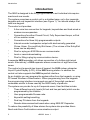
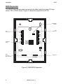
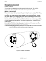
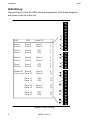
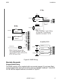
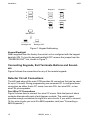
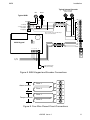
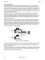
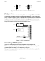
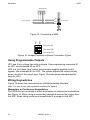
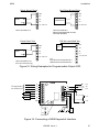
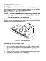
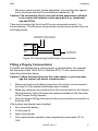
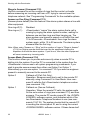
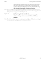
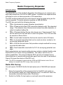
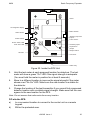
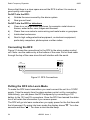
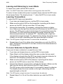
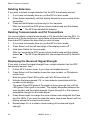
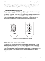
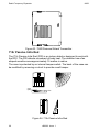
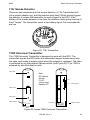
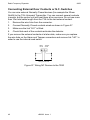
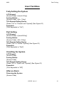
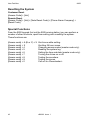
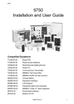
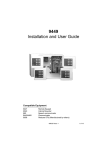
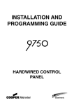
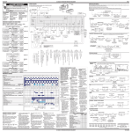
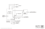
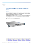
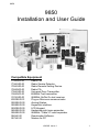
9850
9850
Installation and User Guide
Compatible Equipment
715rEUR-00
719rEUR-00
725rEUR-00
726rEUR-00
735rEUR-00
746rEUR-00
747rEUR-00
8300EUR-01
9925EUR-00
9928EUR-00
9930EUR-00
9855EUR-00
9955EUR-00
956UK-00
957UK-00
Radio PIR.
Radio Smoke Detector.
Radio Remote Setting Device.
Radio PA.
Universal Door Transmitter.
868MHz Test transmitter.
868MHz Go/No Go test receiver.
Plug-on Microcom communicator.
Arming Station.
Keyswitch interface.
LCD Keypad.
Hardwired eight zone expander.
868MHz "Class VI" radio expander.
Downloader Software.
Modem for PC
496363 Issue 1
1
Introduction
9850
Introduction
The 9850 is designed to be fully programmable to suit individual site requirements and user needs.
The system comprises a control unit in a shielded case, up to four separate
keypads and one keyswitch interface (see Figure 1). You should always fit at
least one keypad.
The control unit provides:
°
A four-wire bus connection for keypads, keyswitches and hard-wired or
wireless zone expanders.
°
Connections for either Closed Circuit, Fully Supervised Loops, or End
of Line resistor zones.
°
Connections for three fully programmable outputs.
°
Internal sounder loudspeaker output with electronically generated
Chime, Alarm, Fire and Entry/Exit tones. (The volume of the Entry/Exit
tones can be adjusted).
°
Pins for a plug-on 8300 Microcom communicator.
°
Local or remote downloading.
°
Pins for fitting a plug-by communication device.
A separate 9855 expander unit allows connection of a further eight wired
zones. Alternatively, a 9955 expander allows connection of eight wire-free
zones.
The control unit supports two types of keypad: the 9930 sixteen character
Liquid Crystal Display (LCD), or the 9925 arming station. In addition the
control unit also supports the 9928 keyswitch interface.
As an Installer you can program the system either from the keypads, or using
PC based Windows <Downloader>. When programming from the keypads
the programming interface is arranged as a set of three-digit numbered
commands similar to those used by the 9800 family of products.
The system can provide for up to 8 separate users. User facilities include:
°
Three different security levels (full set and two part sets) which can be
programmed by the Installer.
°
User programmable Duress code.
°
Keyswitch setting/unsetting.
°
Dual key PA alarm from the keypads.
°
Remote telecommand set/unset when using 9955 RF Expander.
To reduce the possibility of false alarms the system also provides Alarm
Abort and Alarm Confirmation communications output.
2
496363 Issue 1
9850
Introduction
725REUR
Telecommand
715REUR
Wire free PIR detector
726REUR
PA
9955
735REUR
Universal transmitter
719REUR
Smoke
detector
Keypads
9925EUR
9930EUR
Wired
detectors
9855
Keypads
Keyswitch
9928EUR
Control
Unit
PIRs
Door contacts
Fused mains spur
Figure 1. 9850 System Layout
496363 Issue 1
3
Technical Specification
9850
Technical Specification
Specification
Operating temperature
= -10° to +55°C
Humidity
= 96% RH
Dimensions
= 310mm W, 385mm H, 95mm D
Weight
= 4.4 kg (without stand-by battery)
Conforms to EN50131-1 Grade 1 and 2 and current BS4737 Part 1 for
remote signalled systems, ACPO-IAS Policy, NACOSS NACP14, ABI log
requirements.
Power Supply
System power supply
Control unit power
9930 Remote Keypad
Standby Battery
= 230VAC (Ambient Temp. 20°. C) 1A total
= 50mA nominal quiescent, 150mA active
= 20mA quiescent with keypad backlight on
= 12 Volt, 7AH or 17AH rechargeable leadacid, Gel Type battery (not supplied). (For
17AH battery kit order part number
8136EUR-02.)
Conforms to EN50131-6 Type A power supply for Grade 1 and 2 systems.
Outputs
O/Ps1 and 2 are relay outputs and O/P 3 is an open collector transistor output.
O/P 1& 2
= voltage free, single pole relay contacts rated
24VDC @ 3A. Max current for external sounder
500mA.
O/P 3
= 500mA, 12VDC. negative applied
ST
Siren Test 14.4VDC (For use in France only)
LS
= can support two parallel connected externally mounted 16 Ohm loudspeakers for
internal sounder or EE tones.
AUX (for detectors)
= 500mA, 12VDC
Coms OP1-4
= 12V logic outputs, -ve applied in alarm (+ve
removed)
Inputs
TR
Tellback/RedCare reset*
LIne Fault input*
= Tamper return for bell.
= +12V applied to operate reset.
= +12V applied to indicate line failure.
* These outputs and inputs appear as pins on the connector for the plug by
communicator".
4
496363 Issue 1
9850
Technical Specification
Fuses
F1 - 12V AUX
= 1A Fast
F2 - Battery
= 2A Anti Surge
Caution: When replacing fuses use the ratings quoted above.
Control Unit PCB and Case
Figure 2 shows the layout of the control unit PCB.
21V AC from
mains transformer
Outputs
Aux Power
12V Aux fuse
Kick Start pins
Keypad and
expander bus
Battery fuse
Battery connector
Tamper switch
connector
Printer connector
RS232 port
Reset pins
Connector for
Plug-by
communicator
Zones
Connector for
Microcom
communicator
Figure 2. Control Unit PCB Layout
496363 Issue 1
5
Installation
9850
9855 Expander
The 9855 Expander provides connectors for either eight four-wire CC loop
zones, FSL or EOL zones. Figure 3 shows the layout of the PC B.
CC/FSL/EOL
Jumpers
Zone
Connectors
Zone
Connectors
Lid Tamper
switch
Spare
Connectors
(Not connected)
Keypad bus
Figure 3. 9850HWX Expander
6
496363 Issue 1
Installation
9850
Wiring the Control Unit
Cable Entries
The control unit case back provides several cable entries. The back is
designed to stand away from the wall to leave space for cables.
Mains Connection
The control unit must be permanently connected to a spur outlet fitted with a
readily accessible disconnect device. Connect the mains supply to the control
unit using the 3-way terminal block located in the control unit back. Secure
the mains cable to the case anchor point using the cable tie provided. Note
that the control unit has a T-250mA internal mains fuse. All electrical connections should be carried out by a qualified electrician and must comply with the
current IEEE Wiring Regulations: 16 Edition, Appendix 5 - Standard Circuit
Arrangement.
Connect the 21VAC lead from the mains transformer to the main pcb. See
Figure 4 for the location of the 21VAC connector.
Caution: Do not apply mains power at this point. Do not work inside the
control unit case when mains power is present.
To Control Panel
Transformer
L
N
230V ~50Hz 200mA
T 250mA 250V
Figure 4. Mains Connection
496363 Issue 1
7
Installation
9850
9850 Wiring
Figures 5 and 6 show the 9850 wiring arrangements. Note these diagrams
are shown in the lid of the unit.
EOL
FSL
4-wire CC
Zone 1
Zone 2
Zone 1
Zone 2
Zone 1
Zone 2
1
2
Zone 3
Zone 4
Zone 3
Zone 4
AT1
AT2
3
4
Zone 5
Zone 6
Zone 5
Zone 6
Zone 3
Zone 4
5
6
Zone 7
Zone 8
Zone 7
Zone 8
AT3
AT4
7
8
Global AT
Zone 9
Zone 10
Zone 5
Zone 6
9
10
Zone 11
Zone 12
AT5
AT6
11
12
Zone 13
Zone 14
Zone 7
Zone 8
13
14
Zone 15
Zone 16
AT7
AT8
15
16
(Input 9 oniy)
Part No 386573 Issue 1
Figure 5. 9850 Wiring
8
496363 Issue 1
9850
Installation
FSL
9850 Wiring
4k7
Alarm contacts
Zone 1
2k2 EOL
Tamper contacts
1
2
4k7
EOL
Zone 2
Alarm contacts
2k2 EOL
Tamper contacts
Alarm contacts
2k2 EOL
Zone 1
Alarm contacts
2k2 EOL
Note: Use zones 1 to 8 if fitting
an expander. If not fitting an
expander use zones 1 to 16.
1
2
3
4
Zone 2
5
6
4-wire CC
7
8
Tamper loop
Zone 1
2k2 EOL
Alarm contacts
9
Note: Use one tamper loop
for all eight detectors. Do not
connect AT10, AT11, AT12, AT13
AT14, AT15 or AT16.
Zone 2
1
2
Zone 1
3
4
Tamper contacts
Zone 2
Figure 6. 9850 Wiring
Remote Keypads
Keypad Addressing
The 9850 control unit is supplied with one remote keypad. If you have fitted
more keypads then each one must be given a separate "address". Links LK2
to LK4 set the keypad address, as shown in Figure 7.
496363 Issue 1
9
Installation
9850
Keypad 1
Address
Keypad 2
2
2
2
3
3
3
4
4
4
Keypad 3
Keypad 4
2
2
3
3
4
4
ON
BACKLIGHT
ON
BACKLIGHT
ON
BACKLIGHT
Backlight ON
Backlight OFF
Figure 7. Keypad Addressing.
Keypad Backlight
When supplied from the factory the control unit is configured with the keypad
backlight ON. To turn the keypad backlight OFF remove the jumper from the
"ON BACKLIGHT" link, shown in Figure 7.
Connecting Keypads, Exit Terminate Buttons and Sounders
Figure 8 shows the connections for any of the remote keypads.
Detector Circuit Connections
The left hand edge of the main PCB provides 24 connectors that can be used
for up to 16 zones. During programming use command 21 to configure these
connectors as either 4-wire CC zones, two wire FSL, two wire EOL, or two
wire FSL plus expander.
Four Wire CC Connections
Figure 9 shows how to connect four wire CC zones. Note that pairs of alarm
contacts alternate with pairs of anti-tamper contacts. The control panel
provides enough connectors for eight four wire circuits. If you wish to connect
16 four wire circuits you must fit a 9855 expander card (see "Connecting a
9855 Expander").
10
496363 Issue 1
9850
Installation
Typical Internal Sounder
16 Ohm Loudspeaker
(2 Max. in parallel)
Bell
Strobe
Typical SAB
+ve
NO
-ve
C
Bell
6-core
-ve Hold Off
-ve Tamper Return
NC
NO
See note
2k2
C
+ve Hold Off
-ve Apply trig
NC
O/P3
TR
Note: Fit a 2k2 resistor for EOL tamper
return, see Command 59.
9930 Keypad
4-core
0V 12V CLK DATA
ST
LS
12V
12V
0V
0V
0V
12V
CLK
DATA
ET
To other
keypads
Exit terminate button
(NO, push to make)
Figure 8. 9850 Keypad and Sounder Connections
Zone 1
1
Zone 2
2
Alarm contacts
Zone 1
Tamper contacts
Zone 2
3
4
Figure 9. Four Wire Closed Circuit Connections
496363 Issue 1
11
Installation
9850
FSL Connections
The control unit zone connectors provide space for up to 16 FSL zones. If
necessary you can connect eight FSL zones to the control unit and eight
zones to a 9855 expander (or eight radio zones to a 9955 radio expander). If
you choose to use an expander then only the first eight zone connectors on
the control unit are active. Remember to use command 21 to select the FSL
zones plus expander option.
Each FSL zone is a ‘Fully Supervised Loop’ using a two wire closed loop.
The loop uses two resistors of different values to differentiate between
‘Circuit’ and ‘Tamper’ signals: a 2K2 resistor fitted in series at the end of the
wired loop (EOL-End-Of-Line), and a 4K7 resistor fitted across the alarm
contact, see Figure 10.
With the loop in a normal state and the alarm contacts closed (shorting out
the 4K7 resistor), the total resistance of the loop is 2K2. When the alarm
contacts open (removing the short from the 4K7 resistor) the resistance of
the loop increases to 6K9 and the control unit detects an alarm condition. If a
tamper device opens then the loop resistance will be open circuit and the
control unit detects a tamper signal.
Figure 10. FSL Connections
To connect a detector to an FSL loop you must wire suitable resistors to the
detector. Always check resistor colour coding before wiring resistors into
circuit, see Figure 11.
The wiring resistance of the cable to the detector (including joints) should be
restricted to a maximum of 100 ohms. The recommended maximum cable
distance per zone is 200 - 300 metres.
12
496363 Issue 1
9850
Installation
4k7
Yellow
Violet
Red
Red
Red
Red
2k2
Gold
Gold
Figure 11. Resistor Colour Code for FSL Resistors
EOL Connections
Each EOL zone is two-wire closed loop that uses a single 2K2 resistor fitted
in series with the alarm contacts to differentiate between "Circuit" and short
circuit "Tamper" signals. Figure 14 shows how to connect two EOL detectors
to adjacent zones. Note that each detector is wired in series to a common
anti tamper circuit connected to terminals marked "9". You must connect a
single 2K2 resistor in series with the anti tamper circuit.
Alarm contacts
2K2 EOL
Zone 1
1
2
3
4
Alarm contacts
2K2 EOL
Zone 2
5
6
7
8
Tamper loop
2K2 EOL
9
Figure 12. EOL Connections
Connecting a 9855 Expander
Figure 13. shows how to wire a 9855 Expander to the control unit.
Make sure you place the jumper link on the expander in the correct position
to select either four-wire CC, or two-wire FSL or EOL.
Once you have connected an expander refer to the instructions supplied in
order to connect detectors.
496363 Issue 1
13
Installation
9850
9855 Expander
0V 12V CLK DATA
0V
12V
CLK
DATA
To other keypads
Control Unit
EOL
FSL
Figure 13. Connecting a 9855
Four-wire CC
Two-wire FSL
Two-wire EOL
Figure 14. Jumper Positions to Select Connection Types
Using Programmable Outputs
OP1 and 2 are voltage free relay contacts. Use programming command 81
for OP1 and command 82 for OP2.
OP3 is a "pull down type" output that provides negative applied control
signals. Use command 83 for OP3. The system adjusts the output polarity
when you select the output type. Figure 15 shows some example applications for OP3.
Wiring Keyswitches
Figure 16 shows the connections for a 9928 Keyswitch Interface.
Note: You can fit only one keyswitch interface per system
Momentary or Continuous Keyswitches
The 9928 can be connected to either momentary or continuous keyswitches,
see Figure 16. When using a momentary keyswitch remove the jumper from
link M/C. When using continuous keyswitches fit a jumper to link M/C.
14
496363 Issue 1
9850
Installation
Shock Sensor Reset
0V
Bell Follow Buzzer/Relay
OP3
OP3
TR
TR
ST
VIPER
+ve
ST
BUZZER/RELAY
LS
LS
+ve 12V Aux
+ve 12V Aux
Use Command 83 4
Use Command 83 0
Relay energises/buzzer sounds
when bell activates.
PIR Set Latch/Walk Test
French Siren Test
OP3
OP3
PIR
TR
0V
SIREN
+ve
TR
ST
ST
LS
LS
+ve 12V Aux
+ve 12V Aux
For:
Set Latch use Command 83 3
Walk Test use Command 83 5
Use Command 83 X1
(for use in France only)
Figure 15. Wiring Examples for Programmable Output OP3
9928
0V
To keypad bus
on control unit.
Set A
12V
0V
Off
CLK
KS2
Set B
DATA
KS1
ET
RDY
Set A
PA
SET
Set B
TAMP
M/C
M/C
M/C
Figure 16. Connecting a 9928 Keyswitch Interface
496363 Issue 1
15
Installation
9850
Installing a Communicator
The 9850 can either be fitted with a Microcom communicator plugged on to
the main PCB, or connected to a separate communication device using a
wiring harness connecting to interface pins on the main PCB. Use programming commands 101 to 154 to set up the communicator.
Fitting a Microcom Communicator
Caution:
Before fitting the Microcom, the control unit must be completely powered down, mains and battery. When reapplying
power, the battery must be connected first. Failure to do so
may result in damage to the control unit.
Fit the Microcom circuit board as shown in Figure 17. Make sure that you do
not bend the long interface pins on the 9850 PCB. Fit four plastic pcb stand
offs between the Microcom and the 9850 PCB.
Figure 17. Fitting a Microcom
Connecting the Telephone Line
Connect the telephone line as follows (see Figure 18):
1. Using a three core cable (type 1/05mm CW1308), strip back 5mm of
two cores and feed through one of the cable entries in the rear of the
9850 casing. Connect the two cores to the terminals, A and B on the
Microcom PCB.
2. Connect the cable from the A and B terminals on the Microcom to the
corresponding terminals on the BT master box.
3. If other apparatus is required to share the telephone line with the
16
496363 Issue 1
9850
Installation
Microcom communicator (series apparatus), connect the main apparatus to the series switched line connections marked A1, B1.
Caution: The connection of only one such series apparatus is allowed
to be connected between a main apparatus (e.g., telephone)
and the PSTN.
Take care to ensure that the A and B line are connected correctly ( i.e.
correct polarity). The Microcom communicator continuously monitors the line
for Ringing tones.
Telephone line to other equipment
for example: Fax, answer machines.
Diverted
Line
A1
Primary
Line
B
A
B1
2 or B
5 or A
BT master Box
(Exclusive Line)
Figure 18. Connecting the Microcom Communicator
Fitting a Plug-by Communicator
The 9850 can be fitted with a communicator or speech dialler (for example
the Scantronic 8400, 8440, 660 or RedCare STU). To fit a communicator,
follow the instructions below.
Caution: Follow the instructions in the order shown, or you may damage the control unit and/or communicator.
1.
Disconnect mains and battery power from the control unit and remove
the case lid, if the system has already been installed.
2. Make any necessary connections from the communicator to the Comms
Wiring Harness. Figure19 shows the outputs available on the free ends
of the Comms Wiring Harness.
3. Plug the Comms Wiring Harness onto the communications connector on
the main PCB.
If the system has already been installed:
4. Re-connect the battery.
5. Fit the case lid .
6. Apply mains power.
7. Test communicator operation (see programming commands 151 to
154).
496363 Issue 1
17
Installation
9850
Comms O/P1 (Brown) -ve applied (+ve removed) in alarm
Comms O/P2 (Orange) -ve applied (+ve removed) in alarm
Comms O/P3 (Yellow) -ve applied (+ve removed) in alarm
Comms O/P4 (Green) -ve applied (+ve removed) in alarm
Line Fail input (Black) +12V applied to indicate telephone line fail
Tel Back Input (Blue) +12V applied to change from engineer to customer reset
0V (Purple)
12V (Red)
Figure 19. Communications Wiring Harness.
Fitting a Battery
Fit a rechargeable battery into the back of the case. The case provides space
for a 12V 7AH battery, or 17AH battery with kit 8136EUR-02.
Initial Start Up
Before applying power to the control unit, ensure that any remote keypad(s)
have been addressed and connected, and that expanders, all zone circuits
and sounders are connected.
1. Connect the battery to the control unit PCB.
2. Briefly short the kick start pins together (they are located above battery
fuse F-2A, see Figure 4).
The green power LED flashes and the internal sounder may sound.
Ignore any display at this stage.
3. Key-in the factory default user access code: 1234.
The internal sounder stops. Ignore any display at this stage.
3. Fit the case lid before applying mains power (this also defeats the
tamper switch).
4. Apply mains power.
The Power LED glows steadily.
5.
Key-in 0 followed by the factory default engineer access code: 7890.
(You do not have to remove the control unit lid.)
Installer Mode
The display shows:
You are now in programming mode.
18
496363 Issue 1
9850
Programming
Programming
Entering Programming Mode
“3. Installation - Initial Power Up” describes how to enter programming mode
for the first time in a new installation. If you wish to enter programming mode
at any other time:
1. Make sure the system is unset.
2. Press 0, then key in the Engineer’s code (default 7890).
Installer Mode
The display shows:
You are now in programming mode.
Note: While the system is in programming mode all keypads except the one you are
using will be locked, displaying the word “Busy”.
Programming Commands
When delivered from the factory the control unit already has default program
settings. To change the default programming you must be in programming
mode. Then:
1. Key in the appropriate command number and press .
The display shows the current value of the command.
Y
2.
Key in digits to select the value you require.
The display shows the new value.
Y
3. Press to store the new value of the command.
If at any time you change your mind, repeat step 1 to 3. The table on the
following pages shows the commands and their options. ( A “Y” next to a
command value shows that it is the factory default.)
The factory default access codes are:
Engineer Code
7890 (567890 for six digit codes)
Access Code User 1 1234 (123456 for six digit codes)
Access Code 2 to 8
Duress Code
X 002 to X 008 (inactive) (X00002...X00008)
X009 (inactive) (X00009 for six digit codes)
Notes:
1. The factory default Access Codes 02 to 08 and the Duress Code must be
changed by USER 1 to a four digit number to activate them. See “9850 User
Guide” for a more detailed explanation of changing user access codes.
2. To change the default zone descriptions use <Downloader>.
496363 Issue 1
19
Programming
9850
To change:
Zone nn
nn
(Note: for zones 1 to 9 key
in “01” to “09”.)
Key-in:
Notes
Default
nn = zone number 01 to 16
a = Zone type, one of:
0 = NU (not used)
Z01 =FEbc
1 = PA (panic alarm)
Z02=ERbc
2 = FR (fire zone)
Z03-Z07=NAbc
3 = NA (normal alarm)
Z08=PA
4 = 24 (24 hour zone)
Z09-Z16=NU
5 = FE (final exit)
6 = ER (entry route)
7 = SA (Shock Analyser)
8 = TC (Technical)
b = Zone attributes, any of:
1 = C (chime)
2 = S (soak test)
3 = D (double knock)
4 = O(Omit allowed)
5 = b (armed in part set B)
6 = c (armed in part set C)
7 = Shock Analyser sensitivity (enter a
number in the range 1 (lowest) to 4
(maximum)
Example: Zone 3 is a Normal Alarm, active in Part Set B, that is Omit Allowed. Type
in:
03
Zone Number
3
Normal Alarm
5
Active in Part Set B
4
Omit Allow
to store the value of the command.
Engineer Code
20 nnnn nnnn = New engineer code
7890
Zone Configuration
21 0
Close Circuit 4 wire
Y
1
End of Line
2
Fully Supervised Loop
3
Fully Supervised Loop plus Expander.
LS Chime Output
22 n
Loudspeaker chime volume
0 = Off ( Keypad only)
1=low, 9=max
5
RedCare reset
23 0
Off
Y
1
On
Internal Sounder
25 0
LS Timed (Follows external bell)
Y
1
Continuous
Sounder Delay on Entry
26 0
Bell Delay Off
1
Bell Delay On
Y
Exit fault external sounder 27 0
Internal
Y
1
Local
YYa b
X
X
X
X
X
X
X
YY
X
X
Y
Y
Y
Y
Y
Y
Y
Y
20
496363 Issue 1
9850
To change:
Status display
PA Response
System Reset
PA Reset
First circuit response
Alarm Abort
Day tamper comms
Level A Exit Mode
System Auto Re-Arm
Bell Delay
Bell Duration
Level A Entry Time
Programming
Key-in:
28 0
1
30 0
1
33 0
1
34 0
1
35 0
1
36 0
1
37 0
1
39 0
1
2
40 0
1
2
3
4
41 0
1
2
3
4
5
6
42 1
2
3
4
5
6
43 1
2
3
4
5
6
Y
Y
Y
Y
Y
Y
Y
Y
Y
Y
Y
Y
Notes
Default
Status off (180 seconds after setting) Y
Status on
Audible
Y
Silent
Eng reset off
Y
Eng reset on
PA cust reset
Y
PA Eng reset
Lock out on
Y
Re-arm
Abort off
Y
Abort on
Day tamper off
Y
Day tamper on
Timed
Y
Terminated
Final door set
Rearm Never
Y
Rearm 1
Rearm 2
Rearm 3
Rearm Always
No delay
Y
1.5 minutes
3 minutes
5 minutes
10 minutes
15 minutes
20 minutes
1.5 minutes
3 minutes
5 minutes
10 minutes
15 minutes
20 minutes
Y
10 Seconds
20 seconds
Y
30 seconds
45 seconds
60 seconds
120 seconds
496363 Issue 1
21
Programming
To change:
Level A Exit Time
9850
Key-in:
Notes
Default
44 1
10 Seconds
2
20 seconds
Y
3
30 seconds
4
45 seconds
5
60 seconds
6
120 seconds
Entry/Exit Volume
45 0
No Entry/Exit tones from Loudspeaker
n
EE tone volume from LS (1=low, 9=max) 5
CSID Code
50 n....n Seed code for remote reset
0000
Set Time and Date
51 .....
see “Setting Time and Date”
Abort reset
53 0
Abort system
Y
1
Abort user
4/6 Digit Access Codes
56 0
Four digit codes
Y
1
Six digit codes.
Battery Load Test
57 0
Disabled
Y
1
Enabled
Day Tamper Indication
58 0
User reset
Y
1
Engineer reset
Sounder Tamper
59 0
Negative voltage tamper return
Y
1
End of line 2k2 resistor.
Level B final exit operation 60 0
B=FE = FE (Final exit)
Y
1
B=FE = NA (Normal alarm)
Level B Entry route
61 0
B=ER = ER (Entry route)
Y
1
B=ER = FE (Start entry timer)
Level B Exit Mode
62 0
Low Tone
Y
1
Instant set
2
Silent set
Level B Alarm response
63 0
Keypad Sounder Only
1
Internal Sounder & keypad sounders Y
2
Local (all sounders, no comms)
3
Full alarm (comms and sounders)
Level B Entry Time
64 1
10 seconds
2
20 seconds
Y
3
30 seconds
4
45 seconds
5
60 seconds
6
120 seconds
Y
Y
Y
Y
Y
Y
Y
Y
Y
Y
Y
Y
Y
Y
22
496363 Issue 1
9850
To change:
Level B Exit Time
Programming
Key-in:
65 1
2
3
4
5
6
Level C Final Exit Operation70 0
1
Level C Entry Route
71 0
1
Level C Exit Mode
72 0
1
2
Level C Alarm Response
73 0
1
2
3
Level C Entry Time
74 1
2
3
4
5
6
Level C Exit Time
75 1
2
3
4
5
6
Output 1 Type, one of
81 0
1
2
3
4
5
6
7
8
9
1
Y
Y
Y
Y
Y
Y
Y
Y
X
Notes
Default
10 Seconds
20 seconds
Y
30 seconds
45 seconds
60 seconds
120 seconds
C=FE = FE (Final exit)
Y
C=FE = NA (Normal alarm)
C=ER = ER (Entry route)
Y
C=ER = FE (Start entry timer)
Low Tone (follows full set exit mode) Y
Instant set
Silent set
Keypad Sounder Only
Internal Sounder and keypad sounders Y
All sounders, no comms
Full alarm (comms and sounders)
10 seconds
20 seconds
Y
30 seconds
45 seconds
60 seconds
120 seconds
10 Seconds
20 seconds
Y
30 seconds
45 seconds
60 seconds
120 seconds
Bell
Y
EE follow
Armed lamp
Set latch
Shock sensor reset
Walk test
Ready lamp
24 hour alarm
Strobe
Smoke sensor reset
Siren Test
496363 Issue 1
23
Programming
To change:
Output 2 Type, one of
Output 3 Type, one of
Burg Comms Rearm
Dual ply entry
Dual key PA
Alarm confirmation
Event log*
Test Output 1*
Test Output 2*
Test Output 3*
24
9850
Key-in:
82 0
1
2
3
4
5
6
7
8
9
1
83 0
1
2
3
4
5
6
7
8
9
1
85 0
1
86 0
1
87 0
1
89 0
1
90 0
1
3
8
Y
Y
Y
Y
Y
Y
Y
Y
92Y
93Y
91
X
X
X
Y
Notes
Default
Bell
EE follow
Armed lamp
Set latch
Shock sensor reset
Walk test
Ready lamp
24 hour alarm
Strobe
Y
Smoke sensor reset
Siren Test
Bell
EE follow
Armed lamp
Set latch
Y
Shock sensor reset
Walk test
Ready lamp
24 hour alarm
Strobe
Smoke sensor reset
Siren Test
Latched
Y
Rearm
Off
Y
On (not recommended in U.K.)
Off
Y
On
Confirm off
Y
Confirm on
Print Event log
View earlier events
View later events
Print config
Cancel printing and viewing
toggle time/date display
Output 1 operates, press or to end
test.
Output 2 operates, press or to end
test.
Output 3 operates, press or to end
test.
496363 Issue 1
X Y
X Y
X Y
9850
To change:
Test Internal Sounder*
Test Keypad Sounder*
Engineer Walk Test*
Load defaults
Leave programming
Programming
Key-in:
94
Notes
Default
Int. sndr operates,
press or to end test.
Kpd sndrs operate,
press or to end test.
Zn indication and chime operate when
cct open
(Clear)
End walk test
98 1
Load defaults
99
Y
95Y
97Y
X Y
X Y
Y
YY
Y
*See “5. Testing”
Communications Programming
To change:
Default
Call mode
Key-in:
101
Y0
1
2
3
Reporting type
103
Y0
1
2
3
Line fail response
106
Y0
1
2
Line integrity checking
Dynamic testing
Three way calling (UK)
Download Mode
Rings to answer
Downloading option
Y0
1
108Y 0
1
109Y 0
1
110Y a Y
107
Notes
Disabled
Single
Alternate
Dual
Fast format
Contact ID
SIA I
SIA II
Disabled
Audible
Silent
Integrity off
Integrity on
Dynamic off
Dynamic on
Three way off
Three way on
a is either:
0
Local
1
Remote
112 0
3 rings
1
5 rings
2
7 rings
3
10 rings
4
15 rings
Y
496363 Issue 1
Y
Y
Y
Y
Y
Y
Y
Y
25
Programming
To change:
Answer on one ring
Downloading option
Access Mode
Communicator Tel No 1
Communicator Tel No 2
Account No
Downloader Tel No 1
Downloader Tel No 2
Fast Format channels
For Microcom
Communicator
Restoral reporting
Reverse Open/Closed
No Close if More Than
1 Zone Omitted
26
9850
Key-in:
Notes
113 0
One ring off
1
One ring on
114 0
Callback off (attended)
1
Callback on
2
Callback any (unattended)
115
Maximum 31 digits
116
Maximum 31 digits
117
Maximum 6 digits
118
Maximum 31 digits
119
Maximum 31 digits
121 a b
a is the channel number 1 to 8
b is one of the following:
0
Not Used
1
Fire
2
PA
3
Burglar
4
Open/Close
5
Alarm Abort
6
Technical Alarm
7
Alarm Confirmation
8
RF Detector Low Battery
9
RF Supervision Loss
1
Jamming
2
AC Fail
3
Tamper Alarm
4
Open
5
Close
6
Zone Omitted
123 0
Restore off
1
Restore on
124 0
Disabled
1
Reverse
125 0
Disabled
1
Enabled
Y
Y
Default
Y
Y
YY
YY
YY
YY
YY
Y Y Y
X
X
X
X
X
X
Y
Y
Y
496363 Issue 1
Y
Y
Y
Y
Y
Y
Y
9850
Programming
To change:
Key-in:
Notes
Default
Country
126 nn
nn = country, one of:
0 = UK (Y)
5 = Italy
0 = Ireland
1 = NL
6 = Spain
1 = OEM 1
2 = Belg. (Flemish)
7 = Denmark
2 = OEM 2
3 = Belg. (French)
8 = Norway
4 = France
9 = Sweden/Finland
Note: If you carry out this command then the system will load all defaults for the
selected country.
Extended Report mode
131 0
Basic
Y
1
Summary
2
Intermediate
3
Full
SIA Tones
132 0
Bell 103
Y
1
CITT V21
Contact ID Options
143 0
Mode Basic
Y
1
Mode Basic + Restore
Plug by Comms Output 1
151 0
Output off (normally high)
1
Fire
Y
2
PA
3
Burglar
4
Open/Close
5
Alarm Abort
6
Technical Alarm
7
Alarm Confirmation
8
RF Detector Low Battery
9
RF Supervision Loss
1
Jamming
2
AC Fail
3
Tamper Alarm
4
Open
5
Close
6
Zone Omitted
Plug by Comms Output 2
152
Default 2 PA
See command 151
Plug by Comms Output 3
153
Default 3 Burglar
See command 151
Plug by Comms Output 4
154
Default 4 Open/CloseSee command 151
Y
X
X
X
Y
Y
Y
Y
X
X
X
X
X
X
Y
Y
Y
496363 Issue 1
27
Programming
9850
Leaving Programming Mode
When all programming has been completed:
1. Key-in ‘99 ’ at the keypad
The display shows:
Y
2.
Y
Press .
The display shows:
followed by the time and date.
99:Exit Eng ?
99:Checking Sys
The system is now in user mode.
Note: If there is a fault on the system , for example an open tamper circuit, the
display shows this and will not return to Day mode. Press (Clear) and rectify
the faults.
Y
Engineer Reset
To perform an Engineer Reset:
1. Check that the display is showing the alarm condition.
2. Key in 0 followed by the Engineer’s code (default 7890), followed by 99
The display shows the time and date.
YY.
Re-entering Programming Mode
You can go back into programming mode whenever the system is unset and
not in alarm:
1. Key in 0 followed by the Engineer’s code (default 7890).
Installer Mode
The display shows:
You are now in programming mode.
Restoring the Access Codes (1st stage reset)
If the user and/or engineer codes are lost, then:
1. First remove mains power and then open the case and disconnect the
battery.
2. Identify the NVM Reset and Kick Start pins on the main pcb.
3. Short the NVM Reset pins together using a small wire link.
4
Short the Kick Start pins together and reconnect the battery.
5. Remove the short from the NVM Reset and Kick Start pins.
The control unit loads the factory default access codes:
User 1: 1234 or 123456 (if six digit codes selected in command 56).
Engineer: 7890 or 567890 (if six digit codes selected in command 56).
6.
7.
28
Close the control unit and apply mains power.
Carry out an engineer reset.
496363 Issue 1
9850
Working with the Downloader
Restoring All Factory Default Programming
If you wish to restore all factory default options then:
1. Enter programming mode (if you are not already there).
2. Key in 98 at the keypad.
The display shows:
98:Load
Y
Default
X to stop the procedure if you change your
3.
Press 1. (You can press
mind at this stage.)
4.
Press .
The keypad gives a double confirmation tone and the system loads the
factory default command values, erasing all previously programmed
values.
Y
Notes:The log is protected and cannot be erased by the Installer.
Working with the Downloader
Download Mode (Command 110)
The 9850 can be programmed from a PC using <Downloader> software. You
can connect the PC to the control unit either over the telephone network, or
locally using a cable.
Use command 110 to manually connect the control unit to the PC.
Local (0)
To connect the control unit to a PC (for example a laptop)
using a local cable key in 110 0 .
Remote (1)
To automatically answer calls coming from a remote PC
over the telephone network key in 110 1 . You will
also need to use commands 112, 113. (Note that Secure
callback does not work with this option.)
Y Y
Y Y
Note: The control unit will leave command 110 if <Downloader> does not make a call
within 30 minutes.
While the control unit is connected to the PC you can upload its programming
configuration into the <Downloader> in order to inspect it. Using
<Downloader> you can change the configuration and then transmit the new
configuration back to the control unit. If you do not wish to change the configuration you can simply monitor the state of the control unit and zones from
the PC.
Use command 114 if you want the control unit to answer incoming calls from
<Downloader> without an engineer being present.
496363 Issue 1
29
Working with the Downloader
9850
Rings to Answer (Command 112)
Use this command to set the number of rings that the control unit waits
before answering an incoming call from a PC trying to connect over the
telephone network. See “Programming Commands” for the available options.
Answer on One Ring (Command 113)
(Answer phone defeat) Use this feature if the alarm system shares a line with
other equipment.
One ring off (0)
Disabled.
One ring on (1)
<Downloader> “warns” the alarm system that a call is
coming by ringing the alarm system number, waiting for
between one and two rings and then hanging up. The
alarm system now knows to expect a call within the next
10 to 90 seconds. <Downloader> then rings the alarm
system again, within 10 to 90 seconds. The alarm system
answers after the first ring.
Note: When using "Answer on 1 Ring" set the number of rings in "Rings to Answer"
(C112) to a higher number than that used by the equipment sharing the
telephone line with the alarm system. If you do not, then the other equipment
will never answer any incoming calls.
Access Mode (Command 114)
This function allows you to provide extra security when a remote PC is
dialling into the system. Once the PC is connected to the system then the
<Downloader> has access to all system programming commands. If you
wish to provide secure access then either use Option 0 or Option 1.
Alternatively you can use option 1 in command 110 if you want an engineer
present to manually connect to the remote PC.
Option 0
Callback off (Call Out Only).
Operation: Someone must start a call to the remote PC
manually using Command 0 in User Mode. User command 0 calls the first <Downloader> telephone number
(see command 118).
Option 1
Callback on (Secure Callback).
Operation: When the remote PC calls, the system waits
for the set number of rings (see command 112) and then
answers. The remote PC sends a panel ID, the <DOWNLOADER> software version, and indicates which of the
two Downloader Telephone Numbers to use (see commands 118/119). The system checks that the remote PC
is sending the correct panel ID, and is using the correct
<DOWNLOADER> software version. If these items don't
30
496363 Issue 1
9850
Working with the Downloader
match then the system hangs up. If the items do match
then the system hangs up and, after a short delay, the
system seizes the telephone line and calls the PC using
the indicated Downloader Telephone Number.
Note: Secure Call Back must be Disabled (Default) until the first “attended” upload
has been performed. This first upload can be carried out either using command
110 option 1, or using command 114 option 0.
Option 2
Callback any (Unattended Mode).
Operation: The control unit answers as soon as the
number of rings set in commands 112 and 113 have
elapsed.
Note: The <Downloader> operator can choose to use Secure Callback, even though
the alarm system is programmed for Unattended Mode.
496363 Issue 1
31
Radio Frequency Expander
9850
Radio Frequency Expander
Introduction
The 9955 RFX is a Class 6 Radio Expander that allows you to connect up to
eight radio detectors to a 9750 or 9850 system. In addition the expander also
provides for up to six telecommands or PA transmitters.
The RFX communicates with the control panel using the same wiring as the
remote keypads. The radio detectors operate on 868.6625MHz.
The RFX can work with the following devices:
a)
719r. A photoelectric smoke chamber type detector.
b)
715r. A Passive Infra Red (PIR) movement detector with 15m standard
range . This detector has a three minute lockout time after detection, in
order to lengthen battery life.
c)
725r. A Remote Setting Device (also known as a “telecommand”) that
can be used to full set, part set or unset the system. The 725r can also
be used as a Panic Alarm.
d)
726r. A small radio transmitter that can be used to start a PA alarm.
e)
735r. A universal transmitter that can be used as a door contact or for
connecting hardwired inputs.
f)
747r. A Go/No Go test meter that provides a simple method for surveying potential radio sites.
g)
746r. A test transmitter used with the 747r for surveying potential user
sites.
Each radio detector and remote setting device contains a digital identity code
that the RFX unit ‘learns’ during installation. The code is one of over 16
million possibilities. This ensures that the RFX unit will not respond to any
other detectors or remote setting switches apart from the ones it has learned.
Figure 20 shows the interior of the RFX unit.
Note: The RFX is designed to work with the 9750 and 9850 control units. Do not
attempt to connect the RFX to any other control unit.
Radio Site Survey
You will need a 747rEUR Go/No Go test meter and a 746rEUR test transmitter.
1. Place the transmitter at the proposed site for the RFX and switch on.
The transmitter sends out a test message every 3.5 seconds. Note: the
transmitter shuts itself down after 30 minutes.
2. Switch the Go/No Go test meter on and walk around the premises.
32
496363 Issue 1
9850
Radio Frequency Expander
Aerial
2x7 Segment display
Radio Section
Select switch
Jamming response
jumper
Delete switch
Learn sensor
Green "Pass" LED
Red "Fail" LED
Address jumper
Supervision
jumper
Tamper switch
Sounder
Connector
0V 12V CLK DATA
Cable entry
Figure 20. Inside the RFX Unit
3.
4.
5.
Hold the test meter at each proposed location for detectors. The test
meter will show a green "Go" LED if the signal strength is adequate.
(You must hold the meter in position for at least 5 seconds.)
Move to a different location to improve the signal strength if the meter
shows a red "No Go" LED. Make sure the new location is suitable for
the detector.
Change the location of the test transmitter if you cannot find a proposed
detector location with a suitable signal strength. Make sure that the user
agrees to the new location for the RFX.
Note: Do not assume that radio works from every location.
DO site the RFX:
a)
In a convenient location to connect to the control unit or a remote
keypad.
b)
Within the protected area.
496363 Issue 1
33
Radio Frequency Expander
9850
Ensure that there is a clear space around the RFX to allow it to receive a
good quality radio signal.
Do NOT site the RFX:
a)
Outside the area covered by the alarm system.
b)
Near ground level.
Do NOT site the RFX or detectors:
a)
Close to or on large metal structures, for example: metal doors or
frames, water tanks, cars, fridges and freezers.
b)
Closer than one metre to mains wiring and metal water or gas pipes.
c)
Inside steel enclosures.
d)
Next to high voltage electrical equipment, or electronic equipment,
particularly computers, photocopiers or other radios.
Connecting the RFX
Figure 21 shows the connections for the RFX to the alarm system control
unit. Note: use the cable entry at the bottom of the case. Do not feed cable
through the top of the case since this will interfere with the aerial.
Control Unit
RFX
0V 12V CLK DATA
DATA
CLK
0V
12V
Figure 21. RFX Connections
Putting the RFX into Learn Mode.
To make the RFX learn transmitters you must connect the unit to a 12VDC
supply. Take the supply from the alarm system control unit by connecting.
Alternatively, you can power the RFX temporarily by connecting a 12V
battery to the 12V and 0V connectors. Once the RFX has learned the detectors it will retain the information if you remove power.
The RFX will go into learn mode when you apply power for the first time with
the lid removed. On going into learn mode the display shows "88" for a few
seconds and then "--". You hear a short double beep.
34
496363 Issue 1
9850
Radio Frequency Expander
Leaving and Returning to Learn Mode
To leave learn mode refit the RFX case lid.
Note: You MUST leave learn mode before removing power from the RFX.
To return to learn mode while power is present simply remove the RFX case
lid and press Select. The display shows "--" when the RFX is in learn mode.
Learning Transmitters
To make the RFX learn any transmitter:
1. If you have not already done so, put the RFX in learn mode.
2. Make sure the activity LED on the transmitter is pointing at the Learn
sensor on the RFX and no more than 100 mm away.
3. Activate the transmitter. (If necessary, activate the tamper on detectors.) Make sure the light from the activity LED shines on the RFX Learn
sensor. The RFX gives a short double beep if it successfully learns the
transmitter. For PAs and telecommands the display shows the total
telecommands learned, for example "t2", alternating with a digit that
represents the signal strength. For detectors the display shows the zone
number on the right, alternating with the signal strength on the left.
Note: The RFX gives a single low tone if it cannot learn the detector .
4.
Repeat steps 2 and 3 for all the other transmitters you wish the RFX to
learn. Remember that the RFX can learn a total of six telecommands or
PA transmitters.
To Learn Detectors to Specific Zones
If you want to learn a detector to a specific zone, then:
1. If you have not already done so, put the RFX in learn mode.
2. Press Select until the display shows the zone number that you want.
If the display is steady then the RFX has already learned a detector for
that zone. If the display is flashing then the zone is free.
3.
4.
Make sure the activity LED of the detector is pointing at the Learn
sensor on the RFX and no more than 100mm away.
Activate the detector. (If necessary, activate the tamper.) Make sure the
light from the activity LED shines on the RFX Learn sensor.
The RFX gives a short double beep if it successfully learns the detector.
The display shows the zone number on the right, alternating with the
signal strength on the left.
Note: The RFX gives a single low tone if it cannot learn the detector .
4.
Repeat steps 2 to 4 for all the other detectors you wish the RFX to
learn.
496363 Issue 1
35
Radio Frequency Expander
9850
Deleting Detectors
If you want to delete a single detector that the RFX has already learned:
1. If you have not already done so, put the RFX in learn mode.
2. Press Select repeatedly until the display shows the zone number of the
transmitter.
3. Press and hold Delete continuously for four seconds.
After four seconds the RFX gives a short double beep and the display
shows "--". The RFX has deleted the detector.
Deleting Telecommands and PA Transmitters
You cannot delete a single telecommand or PA transmitter from the RFX. To
delete one of these devices you must delete all telecommands and PAs and
then make RFX relearn the ones that you wish to keep.
1. If you have not already done so, put the RFX in learn mode.
2. Press Select until the left hand digit of the display shows a "t".
3. Hold down Delete for four seconds.
After four seconds the RFX gives a short double beep and the display
shows "--". The RFX has deleted ALL telecommands and PA transmitters.
Displaying the Received Signal Strength
If you want to show the signal strength from a single detector that the RFX
has already learned, then:
1. Put the RFX in learn mode, if you have not already done so.
2. Press Select until the display shows the zone number, or PA/telecommand count.
Both the green Pass LED and the red Fail LED should be off.
3. Activate the telecommand, PA, or zone detector associated with the
number on the display.
The green Pass LED glows if the signal is strong enough, the red Fail
LED glows if the signal is too weak. The display alternates between the
zone number and the signal strength. Signal strength 2 is the minimum
acceptable strength for a reliable signal.
4.
5.
36
Press Select again to change the zone number and extinguish the Pass
and Fail LEDs. If you want to retest the same zone press Select until the
display shows the correct zone number.
Repeat steps 2 to 4 to obtain a new reading of the received signal
strength.
496363 Issue 1
9850
Radio Frequency Expander
Note that when the display shows a zone number then RFX will ignore all
other zones and PA/telecommands. If the display shows the telecommand
count the RFX will detect any PA/telecommand, but ignore all zones.
725R Remote Setting Device
The user can employ the 725R Remote Setting Device to set, unset and part
set the 9750 and 9780 control units (see Figure 22).
In addition, pressing (Full) and (Off) at the same time will cause a Panic
Alarm. The RFX can use up to six 725R Remote Setting Devices.
The 725R is powered by alkaline cells (Duracell DL 1/3N or CR 1/3N or
K58L) which are available from any major high street camera store.
S
D
PANIC
Figure 22. 725R Remote Setting Device
726R Personal Attack Transmitter
To activate the PA the user presses the two orange keys together. A third
black key allows the user to lock one of the orange keys in the off position,
making the unit safe to carry in a pocket. The RFX can use up to six 726Rs.
The 726R is powered by a lithium cell which is soldered in. The complete unit
must be returned to the Cooper Security Service Department for battery
replacement.
496363 Issue 1
37
Radio Frequency Expander
9850
Figure 23. 726R Personal Attack Transmitter
715r Passive Infra Red
The 715r Passive Infra Red (PIR) is an indoor detector designed to work with
the RFX. The PIR detects movement of body heat. The detector has a fan
shaped sensitive area approximately 15 metres in radius.
The case is protected by an internal tamper switch. The back of the case can
be modified by removing a cutout to provide a wall tamper.
2.4m
(max)
15m
Figure 24. 715r Passive Infra Red
38
496363 Issue 1
9850
Radio Frequency Expander
719r Smoke Detector
There are two components to the smoke detector, a 719r Transmitter built
into a plastic adaptor ring, and the detector body itself. When smoke triggers
the detector it causes the transmitter to send a signal to the RFX. If the
battery of the smoke detector is low then the detector starts giving a series of
short “beeps”. The transmitter sends a low battery signal if its own batteries
are low.
Figure 25. 719r Transmitter
735R Universal Transmitter
The 735R Universal Transmitter is designed to work with the RFX. The
transmitter signals the RFX when the associated magnet moves away from
the case, and sends a restore signal when the magnet is realigned. The case
is protected by an internal/back tamper switch (see Figure 26). The 735R is
powered by two AAA alkaline cells.
Fixing hole
Note:
N/C external
devices:
Fit LK1.
Internal reed:
Remove LK1.
-ve
LK1
Internal reed
+ve
Tamper bar
-ve
Fixing hole
+ve
Cable entries
Tamper switch
Connector
ALARM TAMP
Body
Back
Figure 26. Inside 735R Universal Transmitter
496363 Issue 1
39
Radio Frequency Expander
9850
Connecting External Door Contacts or N.C. Switches
You can wire external Normally Closed devices (for example the 20mm
Quikfit) to the 735r Universal Transmitter. You can connect several contacts
in series, but the control unit will treat them all as one zone. Do not use more
than 10m total cable length from the 735r to the last external contact.
1. Remove the wire links from the connector.
2. Connect Normally Closed contacts wired as shown in Figure 27.
3. Make sure the link "LK1” is fitted.
4. Check that each of the contacts activates the detector.
If you remove the external contacts at a later date, make sure you replace
the wire links on the Alarm and Tamper connectors and remove link "LK1” in
order to use the internal reed switch.
Alarm
circuit
Tamper
circuit
Wiring NC Devices
Figure 27. Wiring NC Devices to the 735R
40
496363 Issue 1
9850
Fault Finding
User Facilities
Fully Setting the System
LCD Keypad
[Access Code] + [Level A Key]
Arming Station
[Access Code] + [No. 1 Key]
725r Remote Setting Device
[Press “Full” or “Closed Lock” Symbol] (See Figure 22)
Keyswitch
[Turn Keyswitch to “Full”]
Part Setting
LCD Keypad
[Access Code] + [Level B Key]
Arming Station
[Access Code] + [No. 2 Key]
725r Remote Setting Device
[Press “Part” or “House” Symbol] (See Figure 22)
Keyswitch
[Turn Keyswitch to “Part”]
Unsetting the System
LCD Keypad
[Access Code]
Arming Station
[Access Code]
725r Remote Setting Device
[Press “Off” or “Open Lock” Symbol] (See Figure 22)
Keyswitch
[Turn Keyswitch to “Off”]
After an Alarm
Disarming the System
[Access Code]
496363 Issue 1
41
User Facilities
9850
Resetting the System
Customer Reset
[Access Code] + [tick]
Remote Reset
[Access Code] + [tick] + [Note Reset Code] + [Phone Alarm Company] +
[Reset Code]
Special Functions
From the 9930 keypad (but not the 9925 arming station) you can perform a
number of other functions, apart from setting and unsetting the system.
These functions are:
[Access code] + A (B or C) + X
[Access code] + X
[Access code] + 4
[Access code] + 5
[Access code] + 6
[Access code] + 7
[Access code] + 8
[Access code] + 9
[Access code] + 0
Omit zone while setting.
Omitting 24 hour zones.
Changing access codes (master code only).
Reading the system log.
Setting the time and date (master code only).
Turning the chime on or off.
Testing the sounders.
Testing the zones.
Call out to <Downloader>.
42
496363 Issue 1