1
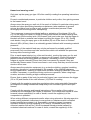
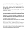
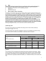
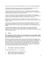
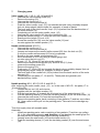
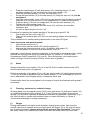
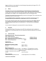
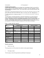
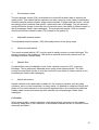
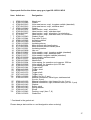
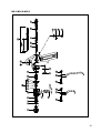
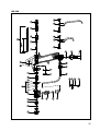
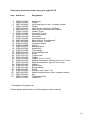
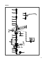
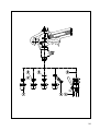
Operating instructions
and spare parts list
- keep for future use -
Airless Spray Gun
Typ: KS-1
KS-1D
KS-1L
KS-1M
KS-2
Art. no.: 071. -00001
Art. no.: 20.. -00001
Art. no.: 071. -00001
Art. no.: 079. -000
Art. no.: 07.. -000
Contents
Hazard and warning notes
Page 3
1. Use for intended purpose
6
2. Basic design, functional principle
7
3. Startup
3.1 Preparations
8
3.2 Function test and startup
4. Operational interruptions, work breaks
9
5. Finishing work
10
6. Operating faults, spray profile errors
10
7. Replacing parts
11
8. Cleaning, maintenance
12
9. Disposal
13
10. Technical data
13
Declaration of Conformity
13
Spare parts for KS-1/KS-1L/KS-2
17/18
Spare parts for KS-1M
19/20
Spare parts for KS-1D
21/22
Accessories
24
2
Hazard and warning notes!
Only start up the spray gun type: KS after carefully reading the operating instructions
in full!
Prevent unauthorised persons, in particular children and youths, from gaining access
to the hazard zone!
Always store the spray gun well out of the reach of children! In particular during work
breaks and when processing hazardous substances, take measures to prevent
misuse by children and youths as well as other unauthorised persons! Clean
thoroughly before storing and/or transporting!
Take measures to prevent accidental pulling or activation of the trigger (22 or 25 e.g. on the edge of a bench or similar)! During work breaks and after finishing work,
immediately fold the safety latch (29) forward (lock) and make sure that the trigger is
blocked and that no material can escape by pulling the trigger (22 or 25). During
work breaks, hang the spray gun on the bracket (B) out of the reach of children!
Above 4 MPa (40 bar), there is a noticeably greater kickback with increasing material
pressure!
Connection of the material feed may only be performed by suitably qualified
personnel! Only use tubes and tube connections which can withhold the pressures
and any other occurring loads!
Prior to each repeat startup (e.g. after work breaks), monitor the spray gun for seal
tightness (no uncontrolled material, no porous or old hoses!). Check connections,
pressure hoses and wearing parts and replace if necessary! Check for material
fatigue at regular intervals! Ensure that hose lines cannot fly around if they are
accidentally disconnected. Route hose lines in such a way that they cannot become
stuck or driven over.
Always wear the protective equipment (e.g. protective clothing, goggles, breathing
protection, gloves etc.) recommended by the supplier of the coating substance
during maintenance, cleaning or repair work and when changing materials! Wear ear
mufflers if necessary, in particular during continuous operation, when using large
nozzles, and when working at high material pressures!
Ensure that no parts of the body (in particular fingers) can come between the trigger
(22 or 25) and handle of the main element (12)! Risk of crushing.
Comply with the explosion protection regulations when using potentially flammable
and explosive coating substances! Keep away from sources of ignition and open
flames!
Comply with the warning and hazard instructions of the supplier of the coating
material and the detergent with regard to emission, fire or explosion hazard or other
hazards (where applicable)! In case of doubt, consult the supplier(s) of the
components in question!
When mixing different components and/or when using solvents or thinning agents to
make coating materials, take steps to ensure that no substances with increased
hazard potential are created (e.g. flammability, explosion hazard, increased
explosive tendency through spraying in air, toxicity, increased toxicity due to
chemical reaction with air etc.)! Avoid increased hazard potential caused by
undesired chemical reactions! In case of doubt, consult the supplier(s) of the
3
components in question! Where necessary, take protective measures and effect
special notification of the particular hazard(s)!
When using substances such as solvents which can generate an increased
explosion potential due to atomisation or spraying in air, take protective measures
and effect special notification of the particular hazard! In case of doubt, consult the
supplier of the components!
The compatibility of the parts of the spray gun which come into contact with the
material cannot be guaranteed with all potential coating substances (see chart "Parts
in contact with the material" in Section 10, Technical Data). In case of doubt, consult
Krautzberger GmbH!
(!)
Under no circumstances should the spray jet be directed at people or animals!
The jet can penetrate the skin, enter the body and force air into the organism. Risk of
fatal embolism!
The material jet is particularly dangerous if no airless nozzle is mounted and
the jet is discharged directly from the valve seat screw!
There is also the risk of poisoning when using poisonous coating substances or
detergents!
Preventive measures: set up an emergency first aid unit in the plant (e.g. first aid
training of suitable employees).
What do to in the case of an accident:
Immediate measures: correct treatment of wounds.
Further measures: immediate treatment by an emergency service doctor who has
been informed of the substance used.
Do not stand in the area of the material jet!
Never direct the spray jet at electrical systems or equipment!
Do not spray workpieces or surfaces which are insufficiently stable! The highpowered spray jet is powerful enough to cause parts of the workpiece or surface to
fly around in the working zone.
During spraying and due to rebound off the workpiece, coating material is discharged
into the surrounding atmosphere. Depending on the coating material used, this can
result in environmental hazards, fire and explosion risk, and health hazards. For this
reason, only use spraying equipment in specially designated areas!
Only work in adequately ventilated areas! If necessary, use suitable extraction
systems!
Ensure adequate earthing (e.g. connection to building earth)!
Radiators or water pipes do not provide sufficient earth contact!
During lengthy breaks in operation or when shutting down the equipment as well as
prior to dismantling or the start of repair and maintenance work, close the shutoff
valve at the material source and press the trigger (22 or 25) until the material
pressure has fully dissipated!
4
During every - even a very brief - break in operation, push the safety lever (29)
forward and check to make sure that the trigger is blocked.
Adhere to the pressures and temperatures listed under "Technical Data"!
If high temperatures are exceeded for a certain period (e.g. > 8 hours at > 43°C, > 10
mins. at > 48°C, or > 1 min. at > 51°C, attach suit able protective devices and post
notification concerning the risk of combustion due to coating substance, and draw
particular attention to risks resulting from leakage or bursting of the spray gun and
the hoses and/or hose connections! If necessary, wear suitable protective clothing
(e.g. goggles, gloves etc.).
In the event of unforeseen occurrences, release the trigger (22 or 25) to interrupt the
material flow! Then immediately push the safety catch (29) to block the trigger. Close
the shutoff valve on the pump.
In the event of unforeseen material discharge (e.g. due to loosening of a material
hose connection or bursting of the material hose), close the shutoff valve at the
material source as quickly as possible! It is advisable to mount the shutoff valve
within reach of the operator of the spray gun to ensure that the unforeseen discharge
of material can be stopped quickly - particularly when using hazardous substances.
Ensure that neither spraying nor material discharge can be activated accidentally or
by defects in the unit as long as one or more persons are in the hazard zone. Take
steps to ensure that no alterations can occur or be made to the material pressure
during setting and maintenance work without the knowledge or consent of the setup
technician!
Ensure adequate illumination of the operating zone!
When using flammable and/or potentially explosive materials, ensure that a fire can
be rapidly extinguished!
Only use spare parts and accessories from Krautzberger GmbH! Krautzberger
GmbH assumes no liability for damage if any external parts are used.
The instructions and notes of EN 1953 "Spraying Equipment for Coating Substances;
Safety Requirements" are to be adhered to, in particular the warning, hazard and
safety notes pertaining to risks and safety requirements and/or measures.
Hazards which exceed those normally expected with the use of spraying equipment
have not come to our attention in the handling of the spray gun type KS or versions
KS-1, KS-1D, KS-1L, KS-1M or KS-2. If, however, accidents or hazardous situations
occur during practical applications, please notify us accordingly.
5
1. Use for intended purpose
The airless spray gun type KS is designed to allow coating of metal, plastic,
ceramics, wood and similar materials as well as other suitable surfaces. Typical
coating substances are, for example, lacquers, paints, water-soluble lacquer
systems, adhesives, oil, release agents etc. It is also suitable for the application of
abrasive materials at operating pressures below 5 MPa (50 bar).
The coating substance to be used is applied to the surface by moving the spray gun
by hand over the surface to be coated and pressing the trigger at the desired point.
The coating substance is fed to the spray gun in liquid form under high material
pressure.
The spray gun works on the airless
principle - in other words, the spray jet is
generated exclusively by the material
pressure pressing the material through a
nozzle. After being discharged from the
nozzle, the spray jet takes on the shape
dictated by the nozzle. It is then directed
at the workpiece. The effective spray jet is
not quite as wide as theoretically possible.
SW = spray angle
TSB = theoretical spraying width
ESB = actual spraying width
The particles of the spray jet reach far
higher speeds than with pneumatically
operated spray guns. The material
throughput is correspondingly higher and
the jet more concentrated (in other words,
the "swirling zone" is smaller). The size
and shape of the jet can only be changed
by changing the nozzle. The diameter of
the nozzle borehole determines the
material flow volume. The size and
geometry of the constantly elliptically
shaped nozzle opening determine the
height and width of the jet (shape of an
elliptical cone).
A wide range of airless nozzles are available and can be obtained from Krautzberger
GmbH.
The nozzle can be rotated steplessly by
360° in the axis of the spray jet and
secured in any position. This allows
optimum adjustment of the angle at which
the jet hits the workpiece to the respective
condition.
The spray gun is particularly suitable for use when relatively large material volumes per
time unit are to be processed. A further advantage compared to pneumatically operated
spray guns is that less spraying mist is created and a far higher percentage of the
material therefore reaches the workpiece. Circulation connection is also possible.
6
(i)
Note
The coating substances approved by the manufacturer of the coating substance for
spraying may be used; however, Krautzberger GmbH offers special designs for
o
substances dissolved in CFC-containing solvents
o
abrasive or
o
corrosive materials.
2.
Basic design, mode of operation
The design of the airless spray gun type KS as well as typical equipment features and
accessories are shown is the diagrams 140-0059, 140-0060, 140-0128 and 140-0064. A
pump supplies the material at a pressure of max. 35 MPa (350 bar) for the versions KS1, KS-1L, KS-1M and KS-2 or max. 25 MPa (250 bar) for the version KS-1D and KS-2D
(400bar for the KS-1D with stainless-steel head section) through a sufficiently pressureresistant hose to the material connection (27). Pulling the trigger (22 or 25) towards the
handle of the main element (12) pushes the valve needle (16) or the needle
reinforcement backwards against the pull-back pressure of the valve spring (19). The
sealing ball of the valve needle or needle reinforcement lifts from the valve seat of the
valve seat screw (4), thus releasing the material flow to the material nozzle (102), from
which the material is sprayed in the form of an elliptical cone jet. The volume of material
discharged depends solely on the nozzle size and the material pressure.
(!) Warning note!
In the risk or the event of an accident, the spray jet can be shut down quickly by
releasing the trigger (22 or 25).
The airless spray gun type KS is supplied in aluminium as standard; the parts coming
into contact with the material are available in stainless steel on request.
Order/Article nos. for the airless spray gun type KS
Material connection
Version
rigid
(without material nozzle)
swivel
rigid
short trigger (22)
swivel
long trigger (25)
Article no.
KS-1
(standard version)
0710-090-0522
0712-090-1128
KS-1D (processing of thick substances)
2007-090-2671
2013-090-1036
KS-1L (long trigger)
0711-090-0526
0713-090-0874
KS1M
(material pipe to handle)
KS-2
(circulation connection)
0798-090-0531
0718-090-....
0720-090-....
0799-090-0535
0719-090-....
0721-090-....
(i) Notes
The version KS-1D is equipped with material ducts with enlarged cross-section. Highly
viscous materials can be processed using appropriate material nozzles. During lengthy
use, fatigue is alleviated by the favourable power transmission (version KS-1L) or the
shift in the centre of gravity towards the handle ((i.e. towards the back) in the version KS1M).
7
In the version KS-2, the coating substance can be circulated through the head section.
Circulation connection is recommended, for example, when using coating substances
which have a tendency to settle or materials whose temperature has to be kept constant.
A swivel-type material connection facilitates handling of the spray gun, as the
hose/hoses do not have to be turned when the user turns the gun.
3.
Startup
3.1
Preparations
>
Push the safety catch (29) forward and make sure that the trigger (22 or 25) can
no longer be activated.
>
If necessary, install a suitable spring (19) for 25MPa
>
Install the material nozzle (102)
>
Earth the spray gun
>
Connect the pressure hose to the material connection (27) - or, in the case of
circulation connection, connect both pressure hoses to the material connections (27)
>
Prepare the coating substance and the accessories for material feed
>
Switch on the material pump
>
Set the material pressure on the regulator or on the material pump or in the return
section of the circulation line
>
Open the shutoff valve at the material source
No material should be discharged at any point.
(!)
Caution!
The material feed should only be connected up by suitably trained personnel! Ensure
that the pressures and temperatures listed under "Technical Data" are not exceeded!
Installation or replacement of the nozzles, springs etc. must be performed by suitably
trained personnel!
3.2
Function test and startup
>
>
>
>
>
>
Push the safety catch (29) upwards (unlock)
Point the nozzle of the spray gun at a test surface
Start the spraying process by pressing the trigger (22 or 25)
Assess spray profile and, if necessary,
after securing the gun using the safety catch (push forwards),
change the nozzle (see Krautzberger GmbH order catalogue for available airless
nozzles)
If necessary, loosen the nozzle nut (1) again
Turn the material nozzle (102) in the desired direction (it can be rotated by 360°)
Tighten the nozzle nut (1)
Push the safety catch (29) upwards (unlock)
Guide the spray jet across the workpiece using even movements
Terminate spraying by releasing the trigger (22 or 25)
>
>
>
>
>
>
(i)
Notes
Only use accessories from Krautzberger GmbH!
Only use sufficiently sturdy hoses! Check (and, if necessary, replace) older hoses before
starting up the spray gun.
8
Only use hoses which fit in the hose connections; ensure correct fit and seal-tightness!
It is advisable to rinse the spray gun through using a suitable detergent prior to first
startup (effect spraying using detergent until it is discharged clear).
To ensure that particles do not block the nozzle, it is advisable to clean the coating
substance through a material filter in front of the material connection (27). High-pressure
material filters are available from Krautzberger GmbH.
In order to achieve uniform layer thickness and spray profile when using high-grade
coatings, it is advisable to apply the substance in cross-wise fashion; in other words, first
coat the surface in horizontal lines and then in vertical lines (or vice-versa).
Material feed is effected via a pump. A circulation connection is recommended, for
example, when using settling coating substances or for materials whose temperature has
to kept constant.
In airless units (unlike pneumatic spray guns), it is generally not possible to change the
spray profile by adjusting the nozzle. If a different spray profile is desired, you must
change the airless nozzle. The spray angle can be altered by using adjustable material
nozzles.
The spray profile depends on, among other factors, the viscosity of the coating
substance and can be altered via the material pressure. If changing the material
pressure does not create an optimum spray profile, it is advisable to repeat the trial using
a different material nozzle.
(!)
Danger
When changing the airless nozzles, it is essential that you not only push the safety
catch (29) forwards and check that the lever is blocked on the trigger (22 or 25) but
also that you close the material feed!
Although no material can escape from the valve seat screw (4) when the trigger (22 or
25) is blocked by the safety catch (29), accidental (or other) pressing of the trigger during
nozzle changing can result in danger to life and limb of all persons in the area of the
spray jet. In such an event, the material jet is discharged from the front opening of the
valve seat screw (4) at high speed. The jet can penetrate the skin, enter the body and
force air into the organism. Risk of fatal embolism! There is also the risk of poisoning
when using poisonous coating substances or detergents!
4.
Interruptions to operation, work breaks
During operational downtimes - e.g. work breaks:
>
>
>
Close the shutoff valve at the material source
Switch off the pump (where applicable)
Push the safety catch (29) forwards (lock)
9
>
>
Pull the trigger (22 or 25) to check that the safety catch (29) blocks the trigger and
no material can be discharged
Hang the spray gun on a hook (using the bracket (B)) or some other suitably
robust fastening device
In all cases, close off the material feed, and ensure that unauthorised persons - in
particular children and youths - cannot gain access to the spray gun.
5.
Finishing work
Releasing the trigger (22 or 25) ends the spraying process. If work is not to be continued,
proceed as follows:
>
Close the shutoff valve at the material source
>
If necessary, switch off the pump
>
Clean the spray gun by filling a suitable detergent (e.g. one recommended or
prescribed by the supplier of the coating substance) into the/a material container
and opening the shutoff valve to convey it through the pump, the material
hose/hoses and the spray gun until it is discharged clear.
>
Push the safety catch (29) forwards (lock)
>
Close the shutoff valve on the pump
>
Switch off the material pump
>
Use suitable means to clean parts on which material is still present
>
Store the spray gun in a place inaccessible to unauthorised persons (in particular
children and youths). If necessary, unscrew the material hose/hoses, clean any
parts which have not been cleaned, disconnect the earth, and lock the spray gun
away.
(i)
Notes
Ensure that no residues of toxic, flammable or explosive material or detergent remain in
the spray gun (avoidance of hazard during storage or transport).
Dispose of any surplus coating substance (e.g. residual amounts) which is not to be
poured back into the storage container in line with the instructions of the producer of the
coating substance. If necessary, effect disposal in a special waste site.
For cleaning of the spray gun and all accessories such as hoses, filters etc. which come
into contact with the material:
o
o
use the detergent recommended or prescribed by the producer of the coating
substance and
then dispose of the detergent in line with the instructions of the producer of the
coating substance or those of the supplier of the detergent. If necessary, effect
disposal in a special waste site.
6.
Operating malfunctions, spray profile defects
If the spray profile is unsatisfactory, check whether the material nozzle is contaminated.
If necessary, insert, clean or replace the material filter.
10
7.
Changing parts
Valve needle (KS-1, KS-1L, KS-1M and KS-2)
>
Unscrew the valve sealing screw (20)
>
Remove the spring (19)
>
Unscrew the nozzle nut (1)
>
Unscrew the valve seat screw (4)
>
Push the valve needle, cmpl. (15) out towards the back using a suitably shaped
(but not sharp-edged) object made (for example) of wood or plastic.
The back end of the valve needle, cmpl. (15) is pushed from the back section of
the main element (12).
>
Completely pull out the valve needle, cmpl. (15)
>
Unscrew the valve needle (16) from the needle bolt (18)
>
Screw the needle pusher (17) onto the new valve needle (16)
>
Exactly set the length (70 mm +0.2)
>
Screw the needle bolt (18) onto the valve needle (16) and
>
counter against the needle pusher (17)
Needle reinforcement (KS-1D)
>
Unscrew the nozzle nut (1)
>
Unscrew the valve seat screw (4)
>
Loosen and unscrew the needle reinforcement (50) from the lock nut (51)
If only the needle reinforcement (50) is to be replaced:
>
Screw on the new needle reinforcement (50)
>
Set a dimension of 24.5 mm using a calliper gauge and
>
counter using the lock nut (51)
If parts (17, 18, 19 and 52) are also to be replaced:
>
Remove the needle reinforcement (50) and lock nut (51), then
>
unscrew the sealing screw (20)
>
Remove the spring (19)
>
Push parts (17, 18 and 52) out towards the back using a suitably shaped (but not
sharp-edged) object made (for example) of wood or plastic
The back end of the needle bolt (18) is pushed from the back section of the main
element (12).
>
Completely pull out parts (17, 18 and 52). These parts are generally not
dismantled any further
Needle packing (KS-1, KS-1D, KS-1L and KS-2)
After removing the valve needle, cmpl. (15) - or, in the case of KS-1D - the parts (17 to
19 and 50 to 52):
>
Loosen the hex nut (14) and remove,
>
together with the insulation washer (13)
>
Pull the head section (6) towards the front and out of the main element (12)
>
Pull the insulating sleeve (11) and the insulating washer (9) off the seal screw (10)
>
Unscrew the seal screw (10) from the head section (6)
>
Remove the packing parts, each consisting of two gaskets (7) and two cup collars
(8). (Use a wire hook to pull out the packing parts. Take care not to damage any
threads!)
Then thoroughly clean all reusable parts.
Assembly:
>
Install new packing parts, each consisting of two gaskets (7) and two cup collars
(8), in the described sequence and direction; do not damage the sealing lips! Do
not use pointed or sharp-edged objects during installation!
>
Loosely screw the seal screw (10) into the head section (6)
>
Push the insulating sleeve (11) and the insulating washer (9) over the seal screw
(10)
11
>
>
>
>
>
>
>
>
Push the head section (6) with seal screw (10), insulating sleeve (11) and
insulating washer (9) into the borehole of the main element (12)
Push the insulating washer (13) over the seal screw (10)
Screw the head section (6) to the seal screw (10) using the hex nut (14), but do
not tighten!
Insert the valve needle, cmpl. (15) into the main element from the back and push
forwards up to the stop (for KS-1D, see replacement of needle reinforcement)
Push the spring (19) over the needle bolt (18) into the main element (12)
Tighten the valve sealing screw (20)
Only then should you tighten the seal screw (10) until there is noticeable
resistance and
counter by tightening the hex nut (14)
Procedure for replacing the needle packing of the spray gun type KS-1M:
>
First loosen the two union nuts (41)
>
Then pull the material pipe (42) from the connecting nipples (after bending it
slightly)
Then proceed as for needle packing replacement in the other KS types.
Valve seat screw and material nozzle
>
Unscrew the nozzle nut (1)
>
Remove the material nozzle (102) and the gasket (3)
>
Unscrew the valve seat screw, cmpl. (4) together with gasket (5)
>
Pull the gasket (5) from the valve seat screw, cmpl. (4)
Assembly, unless already described otherwise, is performed in the reverse order. Lightly
lubricate the moving parts using a suitable grease, e.g. article no. 7026-500 from
Krautzberger GmbH (supplied in 250 g cans). Clean soiled parts, and replace parts
which no longer function properly. Ensure correct seat of gaskets!
(i)
Notes
Always change the valve needle (16) (or in the KS-1D the needle reinforcement (50))
and the valve seat screw (4) together!
Following assembly of the parts (16) to (18), the valve needle (16) should project exactly
70 mm (or as close as possible) from the needle pusher (17). An overlength of up to 0.2
mm is admissible; short lengths result in inadequate valve seat.
Occasionally check the moving parts for free range of motion and lubricate with grease if
necessary!
8.
Cleaning, maintenance, material change
Wearing parts such as material nozzle (102), valve seat screw (4) and valve needle (16)
or needle reinforcement (50), gaskets (3, 5, 7 and 26) and cup collars (8) as well as
springs (19) should be checked at appropriate intervals and replaced if necessary (e.g. if
the valve needle or needle reinforcement does not close sufficiently or if there is
uncontrolled discharge of coating substance).
(!)
Danger
During maintenance and repair work and when changing the nozzle, first close the
shutoff valve at the material source and then press the trigger (22 or 25) until the spray
gun is without pressure. Always wait until the pressure has dissipated!. Then push
the safety catch (29) forwards (lock) and check that the safety catch (29) blocks the
12
trigger and that no more material can be discharged by pressing the trigger (22 or 25).
See hazard and warning notes!
(i)
Notes
The spray gun is never to be dismantled into its individual parts except when this is
necessary for repair or maintenance purposes. When cleaning and during material
change, the gun should be rinsed through thoroughly using a detergent recommended or
prescribed by the supplier of the coating substance until it is discharged clear.
The spray gun should never be completely immersed in detergent! This could destroy the
gaskets and rinse out the lubricant.
During lengthy breaks in operation, the spray gun should be rinsed through with
detergent, left to dry, and stored in a suitable place until it is to be used again.
Do not clean material nozzles and valve seat screw using hard, sharp-edged objects!
(For cleaning of the nozzles, we recommend the flat brush, article no. 7025-015, or
nozzle cleaning needles (see list of accessories, no. 140-0064) from Krautzberger
GmbH.)
A cloth soaked in detergent is recommended for external cleaning.
9.
Disposal
Following dismantling of the spray gun type KS, the metal parts can be sorted and
forwarded to a recycling process; the non-metal parts should be disposed of as special
waste.
10.
Technical data
Operating pressures / Operating temperature
Max. material pressure
(KS-1, KS-1L, KS-1M and KS-2):
Max. material pressure (KS-1D, KS-2D):
Max. material pressure (KS-1D st.st. head section):
Max. material temperature:
50°C
Connections
Material connection:
G1/4 IG
Weight (without add-on parts)
KS-1, KS-1L, KS-1D and KS-2:
KS-1M:
approx. 470 g
approx. 580 g
35 MPa (350 bar)
25 MPa (250 bar)
40 MPa (400 bar)
Material spray zone
Angle of material jet in front of nozzle: up to approx. 110° depending on nozzle
Length of material jet in front of nozzle: up to 5 metres depending on nozzle and
material pressure
Length of material jet with removed
nozzle:
up to 20 metres
Noise emission
Continuous sound pressure level:
nozzle-dependent, 60 to 90 dB(A)
Load due to vibrations
13
Acceleration:
< 2.5 metres/sec.2
Available airless nozzles:
A wide range of airless nozzles are available from Krautzberger GmbH, and we will be
happy to send you more detailed information on request. The order catalogue contains
an overview of the available nozzles. The nozzles differ in their equivalent diameter and
spraying angle.
Graduations of equivalent diameters [mm]: 0.13, 0.18, 0.23, 0.28, 0.33, 0.38, 0.41, 0.46,
0.51, 0.53, 0.61, 0.66, 0.74, 0.79, 0.91, 1.04, 1.10, 1.22, 1.32, 1.57, 1.83 and 2.16
Possible graduations of spraying angle [°]: 5, 10, 15, 25, 35, 40, 50, 60, 65, 73, 80, 95
and 110
The description "equivalent diameters" comprises dimensions for circular boreholes
which correspond to the elliptical openings of the nozzles with regard to throughput
volume. Throughput volumes in output tables expressed in l/min. at 7 MPa (70 bar) refer
to water. These figures vary with materials of different density and/or viscosity. The
effective spraying width (which depends on the spraying angle) is measured using water
at a pressure of 10 MPa (100 bar) at a distance of 30 cm from the workpiece.
Parts in contact with the material
Standard version
Part
designation
Nozzle nut
Material nozzle
Gasket
Valve seat screw
Valve needle
Needle reinforcem.
Gasket
Head section
Head section for
circulation
Gasket
Material connection,
rigid
Material connection,
swivel
Version on request
Material
Art. no
Material
Art. no.
stainless steel
tungsten carbide
(TC)
polyoxymethylene
(POM)
stainless steel + TC
0700-040-1844
0706-080-0015
stainless steel
0707-080-0016
stainless steel + TC
stainless steel + TC
Viton
aluminium
0706-070-0777
2007-080-0031
0700-010-0049
0706-080-0514
stainless steel
0707-070-2300
stainless steel
0765-080-0515
aluminium
0714-080-0687
stainless steel
0773-080-....
NBR
0700-010-0056
stainless steel
0700-040-1653
stainless steel
0700-090-0555
0700-050-....
0700-010-0048
Special equipment
o
Nozzle nut, long
The long nozzle nut (101) protects the material nozzle against damage.
o
Fine-spray nozzle
The fine-spray nozzle (103) generates a particularly fine spray jet.
14
o
Pre-atomiser nozzle
The pre-atomiser nozzle (104) accelerates the material flow and helps to improve the
spray profile. This means that the operator can work using (in some cases) considerably
reduced material pressure and/or larger material nozzle. A large material nozzle - and an
accordingly slower material flow speed - reduces the risk of blockage. The pre-atomiser
nozzle should be chosen to suit the size of material nozzle (see table of airless nozzles in
the Krautzberger GmbH order catalogue). The pre-atomiser nozzle (104) is mounted
directly behind the material nozzle (102) instead of the gasket (3).
o
Adjustable material nozzle
The adjustable material nozzle (105) allows adjustment of the spray angle.
o
Nozzle reversal switch
The nozzle reversal switch (107) can be used to rapidly remove a nozzle blockage. The
nozzle is turned in the retainer by 180° and the ma terial feed briefly opened until the
blockage has been flushed away.
o
Material filter
A material filter can be installed in front of the material connection (27) to prevent
blockage. This is particularly advisable when using small airless nozzles. The filter
screen size should be chosen to suit the nozzle size (see table of airless nozzles in the
Krautzberger GmbH order catalogue).
o
Nozzle extensions
Nozzle extensions are particularly suitable for the coating of cavities such as pipes,
canisters, cans or other containers. In many cases it is possible to adapt the length and
shape of the nozzle extension to the special requirements on the customer's premises.
Ready-made nozzle extensions are also available (see Krautzberger GmbH order
catalogue).
(!) Caution
When working with a nozzle extension, note that explosive mixtures can be created
extremely easily due to the interaction of flammable materials and air in cavities! Ensure
adequate ventilation!
15
Declaration of conformity
under the terms of the EC Directive 89/392 EEC and the amendment directives
91/368/EEC and 93/44/EEC
Krautzberger GmbH, Stockbornstrasse 13, D-65343 Eltville
Design of unit:
Type designation:
Versions:
Make:
Serial nos.:
Airless spray gun
KS
KS-1, KS-1D, KS-1L, KS-1M and KS-2
Krautzberger GmbH
0700-000 and 2000-000
The spray gun type KS and the versions KS-1, KS-1D, KS-1L, KS-1M and KS-2 were
developed, designed and produced in compliance with the EC Directive 89/392/EEC.
The following harmonised standards were applied:
o
EN 292, Safety of Machines, Plant and Equipment
o
EN 1953, Spraying Equipment for Coating Substances, Safety Requirements
(German version prEN 1953: 1995)
The following documents are fully available:
o
Overall diagram of the spray gun type KS and the versions KS-1, KS-1D, KS-1L,
KS-1M and KS-2
o
Detailed and complete diagrams for the checking of compliance of the spray gun
type KS and the versions KS-1, KS-1D, KS-1L, KS-1M and KS-2 with the basic safety
and health safety requirements
o
A list of the basic requirements from EC Directives, standards and specifications
applied during the development, design and production of the spray gun type KS and the
versions KS-1, KS-1D, KS-1L, KS-1M and KS-2
o
A description of the solutions to prevent hazards arising from use of the spray gun
type KS and the versions KS-1, KS-1D, KS-1L, KS-1M and KS-2
o
A copy of the operating instructions
Head of design at Krautzberger GmbH
16
Spare parts list for the airless spray gun, type KS-1/KS-1L/KS-2
Item Article no.
Designation
1
* 3
4
4
* 5
6
6
6
6
* 7
* 8
9
10
11
12
12
13
14
15
15
16
16
17
18
19
19
20
21
22
23
24
25
*26
27
0700-040-1844
0700-010-0048
0706-080-0015
0707-080-0016
0700-010-0049
0706-080-0514
0765-080-0515
0714-080-0687
0773-080-...
0700-010-0043
0700-010-0044
0700-010-0052
0700-040-1648
0700-010-0050
0710-080-0591
0711-080-0592
0700-010-0051
0700-040-0808
0706-070-0852
0706-070-2301
0706-070-0777
0707-070-2300
0700-070-0727
0700-040-0089
0700-020-0004
0700-020-0005
0700-040-1650
0706-040-1644
0706-040-1862
0700-030-1373
0707-040-1676
0707-040-1662
0700-010-0056
0700-090-0555
27
27
28
29
30
31
*32
0700-040-1653
0706-040-1669
0700-040-1645
0700-040-1643
0700-040-1646
0700-040-1647
0700-010-0042
0700-010-0632
Nozzle nut
Gasket
Valve seat screw, cmpl., tungsten carbide (standard)
Valve seat screw, cmpl., stainless steel
Gasket
Head section, cmpl., aluminium
Head section, cmpl., stainless steel
Head section, cmpl., aluminium, for circulation
Head section, cmpl., stainless steel, for circulation
Gasket (2 pcs)
Cup collar (2 pcs)
Insulating washer
Seal screw
Insulating sleeve
Main element with handle piece
Main element without handle piece
Insulating washer
Hex nut
Valve needle, cmpl., tungsten carbide (standard)
Valve needle, cmpl., stainless steel
Valve needle, tungsten carbide (standard)
Valve needle, stainless steel
Needle pusher
Needle bolt
Valve spring, for operation up to approx. 250 bar
Valve spring, for operation up to 350 bar
Valve sealing screw
Trigger shaft
Trigger, short
Screw
Trigger shaft
Trigger, long
Gasket (for circ. 2 pcs)
Material connection, swivel-type, stainless steel
(for circ. 2 pcs)
Material connection, rigid, brass (for circ. 2 pcs)
Material connection, rigid, stainless steel (for circ. 2 pcs)
Washer
Safety catch
Spring washer
Screw
Packing, cmpl. (item 7, 8)
Gasket set
* Contained in the gasket set.
Please always state article no. and designation when ordering!
17
KS-1/KS-1L/KS-2
18
Spare parts list for the airless spray gun, type KS-1M
Item Article no.
Designation
1
3
4
4
* 5
6
6
* 7
* 8
9
10
11
12
12
13
14
15
15
16
16
17
18
19
19
20
21
22
23
24
25
* 26
27
28
29
30
31
* 32
40
41
42
43
Nozzle nut
Gasket
Valve seat screw, cmpl., tungsten carbide (standard)
Valve seat screw, cmpl., stainless steel
Gasket
Head section, cmpl., aluminium
Head section, cmpl., stainless steel
Gasket (2 pcs)
Cup collar (2 pcs)
Insulating washer
Seal screw
Insulating sleeve
Main element with handle piece
Main element without handle piece
Insulating washer
Hex nut
Valve needle, cmpl., tungsten carbide (standard)
Valve needle, cmpl., stainless steel
Valve needle, tungsten carbide (standard)
Valve needle, stainless steel
Needle pusher
Needle bolt
Valve spring, for operation up to approx. 250 bar
Valve spring, for operation up to 350 bar
Valve sealing screw
Trigger shaft
Trigger, short
Screw
Trigger shaft
Trigger, long
Gasket (2 pcs)
Material connection, swivel-type
Washer
Safety catch
Spring washer
Screw
Packing, cmpl. (item 7, 8)
Cutting ring (2 pcs)
Union nut (2 pcs)
Material pipe
Double nipple
Gasket set
*
0700-040-1844
0700-010-0048
0706-080-0015
0707-080-0016
0700-010-0049
0706-080-0514
0765-080-0515
0700-010-0043
0700-010-0044
0700-010-0052
0700-040-1648
0700-010-0050
0798-080-0621
0799-080-0608
0700-010-0051
0700-040-0808
0706-070-0852
0706-070-2301
0706-070-0777
0707-070-2300
0700-070-0727
0700-040-0089
0700-020-0004
0700-020-0005
0700-040-1650
0706-040-1644
0706-040-1862
0700-030-1373
0707-040-1676
0707-040-1662
0700-010-0056
0700-090-0555
0700-040-1645
0700-040-1643
0700-040-1646
0700-040-1647
0700-010-0042
0796-030-0850
0796-030-0851
0796-040-0254
0796-040-0130
0796-010-0632
* Contained in the gasket set.
Please always state article no. and designation when ordering!
19
KS-1M
20
Spare parts list for the airless spray gun, type KS-1D
Item Article no.
Designation
1
* 3
4
* 5
6
6
* 7
* 8
9
10
11
12
12
13
14
17
18
19
20
23
24
25
* 26
27
27
28
29
30
31
* 32
50
51
52
Nozzle nut
Gasket
Valve seat screw, cmpl., tungsten carbide
Gasket
Head section aluminium (250bar)
Head section stainless steel (400bar)
Gasket (2 pcs)
Cup collar (2 pcs)
Insulating washer
Seal screw
Insulating sleeve
Main element, "Krautzberger"
Main element, "neutral"
Insulating washer
Hex nut
Needle pusher
Needle bolt
Valve spring
Valve sealing screw
Screw
Trigger shaft
Trigger
Gasket (for circ. 2 pcs)
Material connection, swivel-type (for circ. 2 pcs)
Material connection, rigid (for circ. 2 pcs)
Washer
Safety catch
Spring washer
Screw
Packing, cmpl. (item 7, 8)
Needle reinforcement, cmpl., tungsten carbide
Nut
Threaded needle
Gasket set
0700-040-1844
2000-010-0533
2007-080-0495
2000-010-0533
2007-040-9165
2000-080-3126
0700-010-0043
0700-010-0044
0700-010-0052
0700-040-1648
0700-010-0050
2007-080-0592
2007-080-0649
0700-010-0051
0700-040-0808
0700-070-0727
0700-040-0089
0700-020-0005
0700-040-1650
0700-030-1373
0707-040-1676
0707-040-1662
0700-010-0056
0700-090-0555
2007-040-1669
0700-040-1645
0700-040-1643
0700-040-1646
0700-040-1647
0700-010-0042
2007-080-0031
2007-030-2913
2007-070-0640
2000-010-0661
* Contained in the gasket set.
Please always state article no. and designation when ordering!
21
KS-1D
22
List of accessories for airless spray gun, type KS
Item Article no.
Designation
101
*102
*103
*104
*105
*106
107
0700-040-1846
0700-050-...
0700-050-...
0700-050-...
8222-050-...
8222-050-...
8222-030-2041
Nozzle nut, long
Material nozzle
Fine-spray nozzle
Pre-atomiser
Material nozzle, adjustable
Nozzle core for nozzle reversal switch
Nozzle reversal switch (without nozzle core)
0700-030-2038
Set of nozzle cleaning needles, size 0, for nozzles up to 0.23
mm dia.
Set of nozzle cleaning needles, size 1, for nozzles up to 0.33
mm dia.
Set of nozzle cleaning needles, size 4, for nozzles from 0.38
mm dia.
0700-030-2039
0700-030-2040
Always state article no. and designation when ordering!
* Please additionally specify desired type and size of these articles when ordering!
23
24