1
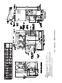
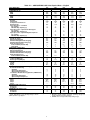
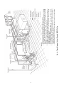
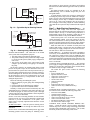
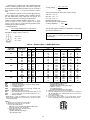
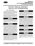
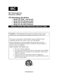
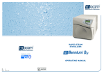
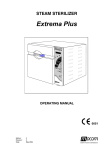
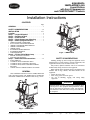
AQUASNAP® 30MPA,MPW015-045 Liquid Chillers with Scroll Compressors and COMFORTLINK™ Controls Installation Instructions CONTENTS Page GENERAL . . . . . . . . . . . . . . . . . . . . . . . . . . . . . . . . . . . . . . . . 1 SAFETY CONSIDERATIONS . . . . . . . . . . . . . . . . . . . . .1,2 INSTALLATION . . . . . . . . . . . . . . . . . . . . . . . . . . . . . . . . 2-17 Location. . . . . . . . . . . . . . . . . . . . . . . . . . . . . . . . . . . . . . . . . . 2 Step 1 — Inspect Shipment. . . . . . . . . . . . . . . . . . . . . . . 7 Step 2 — Position the Unit. . . . . . . . . . . . . . . . . . . . . . . . 7 Step 3 — Place the Unit . . . . . . . . . . . . . . . . . . . . . . . . . . 7 Step 4 — Check Compressor Mounting . . . . . . . . . . 7 Step 5 — Make Piping Connections . . . . . . . . . . . . . . 7 • 30MPA SYSTEM CONDENSER • EVACUATION AND DEHYDRATION • 30MPW CONDENSER DESCRIPTION • 30MPW CONDENSER • 30MPW UNITS • EVAPORATOR DESCRIPTION • EVAPORATOR PIPING • AIR SEPARATION Step 6 — Fill the Chilled Water Loop . . . . . . . . . . . . 14 • WATER SYSTEM CLEANING • FILLING THE SYSTEM Step 7 — Make Electrical Connections . . . . . . . . . . 15 • FLOW SWITCH • CONTROL BOX, POWER SECTION • CONTROL BOX, CONTROLS SECTION • CONTROL BOX, FIELD CONTROL WIRING SECTION • UNBALANCED 3-PHASE SUPPLY VOLTAGE GENERAL These installation instructions cover the 30MPA, MPW units with ComfortLink controls. The 30MPA units are condenserless units and the 30MPW units are all fluid cooled. See Fig. 1 and 2. a30-5030 Fig. 2 — 30MPW Unit SAFETY CONSIDERATIONS Installing, starting up, and servicing this equipment can be hazardous due to system pressures, electrical components, and equipment location (roofs, elevated structures, etc.). Only trained, qualified installers and service technicians should install, start up, and service this equipment. When working on the equipment, observe precautions in the literature and on tags, stickers, and labels attached to the equipment. • Follow all safety codes. • Wear safety glasses and work gloves. • Use care in handling, rigging, and setting bulky equipment. WARNING Electrical shock can cause personal injury and death. Shut off all power to this equipment during installation. There may be more than one disconnect switch. Tag all disconnect locations to alert others not to restore power until work is completed. a30-5029 Fig. 1 — 30MPA Unit Manufacturer reserves the right to discontinue, or change at any time, specifications or designs without notice and without incurring obligations. Catalog No. 04-53300077-01 Printed in U.S.A. Form 30MP-5SI Pg 1 612 11-11 Replaces: 30MP-1SI INSTALLATION . WARNING Location — Do not store units in an area exposed to weath- DO NOT USE TORCH to remove any component. System contains oil and refrigerant under pressure. To remove a component, wear protective gloves and goggles and proceed as follows: a. Shut off electrical power to unit. b. Recover refrigerant to relieve all pressure from system using both high-pressure and low pressure ports. c. Traces of vapor should be displaced with nitrogen and the work area should be well ventilated. Refrigerant in contact with an open flame produces toxic gases. d. Cut component connection tubing with tubing cutter and remove component from unit. Use a pan to catch any oil that may come out of the lines and as a gage for how much oil to add to the system. e. Carefully unsweat remaining tubing stubs when necessary. Oil can ignite when exposed to torch flame. Failure to follow these procedures may result in personal injury or death. er because of sensitive control mechanisms and electronic devices. Locate unit indoors. Model number structure is shown in Fig. 3. See Fig. 4 and 5 for unit dimensional details. When considering location, consult National Electrical Code (NEC) and local code requirements. Allow sufficient space for wiring, piping, and service. Install unit in an area where it will not be exposed to ambient temperatures below 50 F (10 C). Allow 36 in. (914 mm) in front of the unit for control box access door. Additional clearance may be required per local codes. Prior to installation determine which direction compressor will be removed, and leave 3 to 4 ft (914 to 1219 mm) clearance for removal. On all units leave 3 ft (0.9 m) of clearance behind the unit to make water/brine connections to the evaporator, accessing the TXV (thermostatic expansion valve), fluid thermistors, and proof of flow switch. On all units, leave 2 ft (610 mm) on one side for making refrigeration connections (30MPA) or fluid connections (30MPW) to condenser. See Fig. 4 and 5. The floor must be strong enough to support the unit operating weight (see Tables 1A and 1B and Fig. 4-6). If necessary, add a supporting structure (steel beams or reinforced concrete slabs) to the floor to transfer weight to nearest beams. Additional weight of factory-installed sound enclosure option is 75 lb (34 kg). CAUTION DO NOT re-use compressor oil or any oil that has been exposed to the atmosphere. Dispose of oil per local codes and regulations. DO NOT leave refrigerant system open to air any longer than the actual time required to service the equipment. Seal circuits being serviced and charge with dry nitrogen to prevent oil contamination when timely repairs cannot be completed. Failure to follow these procedures may result in damage to equipment. CAUTION Be sure interconnecting piping and electrical conduits are suspended freely, and are not in contact with any adjacent walls. Be sure unit capillaries are not rubbing against anything. Damage to unit or walls may result. 30MP A 030 6 0 - 0 0 0 5 Condenser Option A – Chiller without Condenser (Air-Cooled) W – Chiller with Condenser (Water-Cooled) Packaging Options 5 – Bag, No Compressor Insulation (Std) 7 – Bag, Compressor Insulation B – Export Crating, No Compressor Insulation D – Export Crating, Compressor Insulation Unit Size – Nominal Tons (kW) 015 – 15 (53) 040 – 40 (141) 020 – 20 (70) 045 – 45 (158) 030 – 30 (106) Controls/Interface Options 0 – Scrolling Marquee Display (Std) 5 – Scrolling Marquee Display, EMM 30MP – AquaSnap® Liquid Chiller with ComfortLink™ Controls Disconnect Options 0 – Standard (Terminal Block) 1 – Non-Fused Disconnect Switch Voltage Options 1 – 575-3-60 2 – 380-3-60 5 – 208/230-3-60 6 – 460-3-60 Capacity Control Options 0 – Standard 4 – High Interrupt and Hot Gas Bypass 1 – Hot Gas Bypass 2 – Digital Compressor 5 – High Interrupt and Digital Compressor 3 – High Interrupt Sound/Mounting Options 0 – None 1 – Sound Enclosure Panels 3 – Height Adjustment Kit 4 – Height Adjustment Kit, Sound Enclosure Panels 9 – Mobility Kit (Wheels) B – Mobility Kit (Wheels), Sound Enclosure Panels D – Height Adjustment Kit, Mobility Kit (Wheels) F – Height Adjustment Kit, Mobility Kit (Wheels), Sound Enclosure Panels LEGEND EMM — Energy Management Module 612 0 Comfort Cooling/Medium Temp Brine Options 0 – Comfort Cooling Duty (32-60 F) (0.0°-16.5 C) (Std) 7 – Medium Temperature Brine (15-32 F) (–9.4-0.0° C) Design Revision Level - – Initial Release a30-5425 Fig. 3 — 30MP Model Number Nomenclature 2 934 (424 kg) 30MPA045 3 D 25.90 (658 mm) 26.00 (660 mm) 17.50 (445 mm) 17.40 (442 mm) 5.99 (152 mm) 5.87 (149 mm) LIQ. LINE SOLENOID VALVE 33.49 (851 mm) 33.50 (851 mm) D 5.54 (141 mm) OPPOSITE CONTROL PANEL END OUT COOLER IN 26.00 (660 mm) 17.00 (432 mm) 30.69 (780 mm) 31.39 (797 mm) 25.20 (640 mm) C 17.60 (447 mm) B 31.49 (800 mm) A 17.80 25.10 (452 mm) (638 mm) 17.72 (450 mm) 17.95 (456 mm) 18.50 (470 mm) F P,T ACCESS PORTS 1/4" FPT ACCESS 3 2 1/4" SAE FLARE RELIEF CONNECTION OUT STD UNIT 55.00 [1397 ] 52.30 [1328 ] MOUNTING HOLES 9/16" OPTIONAL SOUND ENCLOSURE 57.00 [1448] - FORK POCKETS COOLER B Fig. 4 — Dimensions — 30MPA015-045 Units 1.75 [44 ] IN OPTIONAL SOUND ENCLOSURE 48.42 [1230] COMPRESSOR (SEE TABLE FOR QTY) NO.OF COMPRESSORS WATER CONNECTIONS (IN/OUT) 2" VICTAULIC (015-020) 2 1/2" VICTAULIC (030-045) 11.00 (279 mm) 11.12 (282 mm) 6.44 (164 mm) E NOTES: 1. Operating weight includes weight of water and refrigerant. 2. Denotes center of gravity. 3. Dimensions are shown in inches. Dimensions in [ ] are in millimeters. 4. Allow 36-in. (914 mm) clearance on control panel end, opposite control panel end and above the unit. All clearances must be in accordance with local codes. 5. Denotes accessory or factory-installed option. C E 913 (414 kg) 30MPA040 F 722 (327 kg) 30MPA030 OPTIONAL SOUND ENCLOSURE 65.05 [1652] 626 (284 kg) 635 (288 kg) 30MPA015 30MPA020 OPERATING WEIGHT (lb) UNIT 3.85 [98 ] MOBILITY KIT (WHEEL) OPTIONAL LIQ. LINE ISOLATION VALVE REMOTE CONDENSER CONNECTION ENSURE CLEARANCE PER LOCAL CODES CONTROL PANEL END OF UNIT CONTROL BOX ACCESS DOOR CLEARANCE 36"(914) NON-FUSED DISCONNECT (OPTIONAL) OPTIONAL SOUND ENCLOSURE 040,045 TON ONLY POWER ENTRY FIELD CONNECTION (4) 7/8" K.O - A CONTROL PANEL END STD UNIT 32.00 [813 ] 29.13 [740 ] MOUNTING HOLES 9/16" COOLER OPTIONAL SOUND ENCLOSURE 32.12 [816] 4.03 [102 ] 4.00 [102] ISOLATOR-OPTIONAL 62.50 [1588 ] SCROLLING MARQUEE DISPLAY 4.46 [113] a30-5032 4 Fig. 5 — Dimensions — 30MPW015-045 Units NOTES: 1. Operating weight includes weight of water and refrigerant. 2. Denotes center of gravity. 3. Dimensions are shown in inches. Dimensions in [ ] are in millimeters. 4. Allow 36-in. (914 mm) clearance on control panel end, opposite control panel end and above the unit. All clearances must be in accordance with local codes. 5. Denotes accessory or factory-installed option. a30-5033 Table 1A — 30MPA,MPW015-045 Units Physical Data — English UNIT 30MPA,MPW NOMINAL TONS OPERATING WT (lb) MPA MPW REFRIGERANT (lb) MPA* MPW COMPRESSOR Quantity Speed (rpm) Compressor Nominal Tons Oil Charge (pt) Capacity Control — Standard No. of Steps Minimum Step Capacity (%) Capacity Control — Optional Hot Gas Bypass No. of Steps Minimum Step Capacity (%) Capacity Control — Optional Digital Compressor No. of Steps Minimum Step Capacity (%) EVAPORATOR Weight (lb, empty) Net Fluid Volume (gal.) Maximum Refrigerant Pressure (psig) Maximum Fluid-Side Pressure (psig) Water Connections (in.) Inlet and Outlet (Victaulic IPS) Drain (NPT) CONDENSER (30MPW Only) Weight (lb, empty) Net Fluid Volume (gal.) Maximum Refrigerant Pressure (psig) Maximum Fluid-Side Pressure (psig) Water Connections (in.) Inlet and Outlet (Victaulic IPS) CONDENSER REFRIGERANT CONNECTIONS (30MPA Only) Liquid Line (ODS) (in.) Discharge Line (ODS) (in.) CHASSIS DIMENSIONS (in.) Length Width Height MINIMUM SYSTEM FLUID VOLUME (gal. per Ton) Normal Air Conditioning Standard Optional Hot Gas Bypass Optional Digital Compressor Low Outdoor Ambient Cooling Operation (30MPA Units) Standard Optional Hot Gas Bypass Optional Digital Compressor CAPACITY STEPS Step 1 Step 2 Step 3 Step 4 MINIMUM FLOW RATES (gpm) Evaporator Condenser MAXIMUM FLOW RATES (gpm) Evaporator Condenser 015 15 020 20 030 30 040 40 045 45 626 680 635 704 912 1097 934 1190 8.2 11.8 10.7 15.3 14.7 27.3 15.1 34.5 2 3500 7.5 10.6 2 3500 10 13.8 721 860 R-410A 12.5 21.0 Scroll, Hermetic 2 3500 15 13.8 3 3500 13 20.6 3 3500 15 20.6 2 50 2 50 2 50 3 33 3 33 3 18 3 25 3 34 4 21 4 22 — — 22 15 22 15 33 10 33 10 27.5 0.8 505 300 40.3 1.2 505 300 91.8 2.4 565 300 122.3 3.2 565 300 128.3 3.4 565 300 2 2 1/ 1/ 2 1 /2 1/ 2 2 1 /2 1/ 2 2 1 /2 1/ 2 2 2 34.9 1.2 505 300 43.6 1.6 505 300 104.6 2.9 565 300 136.7 4.1 565 300 188.3 5.9 565 300 1 1 /2 1 1 /2 2 2 2 1/ 2 1 3 /8 1/ 2 1 3 /8 5/ 8 1 3 /8 5/ 8 1 5 /8 5/ 8 1 5 /8 55 32 62.5 55 32 62.5 55 32 62.5 55 32 62.5 55 32 62.5 6 4 — 6 4 3 6 4 3 3 3 3 3 3 3 10 10 — 10 10 6 10 10 6 6 6 6 6 6 6 100% 50% 18%† — 100% 50% 25%† — 100% 50% 34%† — 100% 67% 33% 21%† 100% 67% 33% 22%† 22 22 28 28 43 43 55 55 64 64 74 74 97 97 148 148 188 188 220 220 * 30MPA units (condenserless) are shipped with nitrogen holding charge. Approximate cooler operating charge is shown. † With optional hot gas bypass. NOTES: 1. Operating weight includes refrigerant operating charge and weight of fluid in the heat exchangers. 2. 30MPW units are shipped with full operating charge. 5 Table 1B — 30MPA,MPW015-045 Units Physical Data — SI UNIT 30MPA,MPW NOMINAL kW OPERATING WT (kg) MPA MPW REFRIGERANT (kg) MPA* MPW COMPRESSOR Quantity Speed (r/s) Compressor Nominal kW Oil Charge (L) Capacity Control — Standard No. of Steps Minimum Step Capacity (%) Capacity Control — Optional Hot Gas Bypass No. of Steps Minimum Step Capacity (%) Capacity Control — Optional Digital Compressor No. of Steps Minimum Step Capacity (%) EVAPORATOR Weight (kg, empty) Net Fluid Volume (L) Maximum Refrigerant Pressure (kPa) Maximum Fluid-Side Pressure (kPa) Water Connections (in.) Inlet and Outlet (Victaulic IPS) Drain (NPT) CONDENSER (30MPW) Weight (kg, empty) Net Fluid Volume (L) Maximum Refrigerant Pressure (kPa) Maximum Fluid-Side Pressure (kPa) Water Connections (in.) Inlet and Outlet (Victaulic IPS) CONDENSER REFRIGERANT CONNECTIONS (30MPA Only) Liquid Line (ODS) (in.) Discharge Line (ODS) (in.) CHASSIS DIMENSIONS (mm) Length Width Height MINIMUM SYSTEM FLUID VOLUME (L per kW) Normal Air Conditioning Standard Optional Hot Gas Bypass Optional Digital Compressor Low Outdoor Ambient Cooling Operation (30MPA Units) Standard Optional Hot Gas Bypass Optional Digital Compressor CAPACITY STEPS Step 1 Step 2 Step 3 Step 4 MINIMUM FLOW RATES (L/s) Evaporator Condenser MAXIMUM FLOW RATES (L/s) Evaporator Condenser 015 54 020 71 030 108 040 138 045 161 284 308 288 319 414 498 424 540 3.7 5.3 4.9 6.9 6.7 12.4 6.8 15.6 2 58 26 5.0 2 58 35 6.5 327 390 R-410A 5.7 9.5 Scroll, Hermetic 2 58 53 6.5 3 58 45 9.8 3 58 53 9.8 2 50 2 50 2 50 3 33 3 33 3 18 3 25 3 34 4 21 4 22 — — 22 15 22 15 33 10 33 10 12.5 2.9 3482 2068 18.3 4.6 3482 2068 41.6 8.9 3896 2068 55.5 12.0 3896 2068 58.2 13.0 3896 2068 2 2 1/ 1/ 2 1 /2 1/ 2 2 1 /2 1/ 2 2 1 /2 1/ 2 2 2 15.8 4.5 3482 2068 19.8 5.9 3482 2068 47.4 11.1 3896 2068 62.0 15.4 3896 2068 85.4 22.4 3896 2068 1 1 /2 1 1 /2 2 2 2 1/ 2 1 3 /8 1/ 2 1 3 /8 5/ 8 1 3 /8 5/ 8 1 5 /8 5/ 8 1 5 /8 1397 813 1588 1397 813 1588 1397 813 1588 1397 813 1588 1397 813 1588 6.5 4.3 — 6.5 4.3 3.3 6.5 4.3 3.3 3.3 3.3 3.3 3.3 3.3 3.3 10.8 10.8 — 10.8 10.8 6.5 10.8 10.8 6.5 6.5 6.5 6.5 6.5 6.5 6.5 100% 50% 18%† — 100% 50% 25%† — 100% 50% 34%† — 100% 67% 33% 21%† 100% 67% 33% 22%† 1.4 1.4 1.8 1.8 2.7 2.7 3.5 3.5 4.0 4.0 4.7 4.7 6.1 6.1 9.3 9.3 11.9 11.9 13.9 13.9 * 30MPA units (condenserless) are shipped with nitrogen holding charge. Approximate cooler operating charge is shown. † With optional hot gas bypass NOTES: 1. Operating weight includes refrigerant operating charge and weight of fluid in the heat exchangers. 2. 30MPW units are shipped with full operating charge. 6 designed to support the unit weight. If necessary, add structural support to floor. Also, be sure the surface for installation is level. Refer to Fig. 4 and 5 for space requirements and weight distribution. Only electrical power connections, water connections for condenser, fluid connections for evaporator, and strainer installation are required for 30MPW installation. Installation of 30MPA units varies only in field piping required for the remote condenser. When the unit is in its final position, remove the packaging and remove the mobility kit wheels (if equipped). Remove 3/ -in. wheel nuts to remove wheels from unit legs. Level the 8 unit (using a level), and bolt the unit to the floor or pad. If unit is to be mounted on unit external vibration isolators, follow the mounting instructions included with the accessory vibration isolator. If unit has accessory leveling kit installed, follow the instructions provided with the accessory to make sure unit is level and in the correct position. Step 1 — Inspect Shipment — Inspect unit for damage or missing parts. If damaged, or if shipment is incomplete, file a claim immediately with the shipping company. CAUTION Unit is top heavy. Unit may tip if handled without care. Damage to unit or injury may result. Step 2 — Position the Unit — The unit may be moved by means of rollers under the rails or a forklift truck. If accessory mobility kit is to be used, install this accessory after bringing unit into building and before moving the unit to its final location per installation instructions provided with the accessory. The factory-installed mobility kit option consists of 4 swivel-type wheels that are field-mounted to the legs of the unit. See Fig. 7. NOTE: The wheels are equipped with a thumb-screw brake. Step 4 — Check Compressor Mounting — As shipped, units with two compressors are held down with 6 bolts through rubber grommets. All units with three compressors are held down with 8 bolts per pair through grommets. After unit is installed, verify that mounting bolt torque is 7 to 10 ft-lb (9 to 14 Nm). a30-5040 Step 5 — Make Piping Connections — See Fig. 8 and 9 for typical piping applications. 30MPA SYSTEM CONDENSER — For detailed condenser piping installation instructions for 30MPA systems, refer to separate instructions packaged with the remote condenser units. Condenser refrigerant piping for 30MPA units should be sized to minimize the amount of refrigerant required. Consider the length of piping required between the condenser and indoor unit, the amount of liquid lift, and the compressor oil return. Suction and liquid lines should be sized in accordance with Table 2. Liquid line refrigerant chart is shown in Table 3. Double discharge risers may be required for proper oil return if condenser is located above the chiller and if hot gas bypass is installed, or if unit is used for medium temperature brine application. Double discharge risers are required for all units with digital compressors. See Table 4 and Fig. 10. D A CONTROL PANEL SIDE WEIGHT DISTRIBUTION AT EACH MOUNTING HOLE — Lb (kg) UNIT 30MP A015 A020 A030 A040 A045 W015 W020 W030 W040 W045 A MOUNTING HOLE B C 156 (71) 159 (72) 181 (82) 228 (104) 234 (106) 170 (77) 176 (80) 216 (98) 275 (125) 298 (135) D Table 2 — Single Circuit 30MPA Line Sizing Chart Fig. 6 — Mounting Hole Weight Distribution TOTAL LINEAR LENGTH OF UNIT INTERCONNECTING PIPE REFRIGERANT ft (m) CONNECTIONS (CHILLER 30MPA 0 - 50 50 - 100 100 - 200 UNIT CONNECTION (0 - 15.4) (15.4 - 30.5) (30.5 - 61.0) SIZE) Equiv. Pipe Equiv. Pipe Equiv. Pipe ODS Length = 75 ft Length = 150 ft Length = 300 ft L (in.) D (in.) L (in.) D (in.) L (in.) D (in.) L (in.) D (in.) a30-5041 015 1/ 2 1 3 /8 1/ 020 1/ 2 1 3 /8 5/ 030 5/ 8 1 3/ 8 7/ 040 5/ 8 1 5/ 8 7/ 045 5/ 8 1 5/ 8 7/ Fig. 7 — Mobility Kit D Step 3 — Place the Unit L NOTE: These units are not suitable for unprotected outdoor use. Carrier recommends that these units be located in the basement or on the ground floor. However, if it is necessary to locate the unit on an upper floor, be sure the structure has been 1 3 /8 5/ 8 1 3 /8 5/ 8 13/ 8 7/ 8 15/ 8 7/ 8 15/ 8 7/ 2 8 1 3 /8 5/ 8 1 3 /8 8 1 3 /8 7/ 8 1 3 /8 8 13/ 8 7/ 8 15/ 8 8 15/ 8 8 1 1 /8 1 1 /8 1 3 /8 1 5 /8 1 5 /8 LEGEND — Discharge Line Size (discharge line size is equal to the chiller connection size) — Liquid Line Size (liquid line size is equal to or greater than the chiller connection size) NOTES: 1. Shaded areas indicate double discharge riser required if unit is equipped with hot gas bypass or operation below 40 F LWT (Leaving Water Temperature). 2. All units with digital compressors require double discharge riser. 7 a30-4997 8 Fig. 8 — Typical Piping with Liquid-Cooled 30MPW Chiller NOTES: 1. Chiller must be installed level to maintain proper compressor oil return. 2. Wiring and piping shown are general points-of-connection guides only and are not intended for a specific installation. Wiring and piping shown are for a quick overview of system and are not in accordance with recognized standards. Units should be installed using certified drawings. 3. All wiring must comply with applicable local and national codes. 4. All piping must follow standard piping techniques. Refer to Carrier System Design Manual or appropriate ASHRAE (American Society of Heating, Refrigerating, and Air Conditioning Engineers) handbook for details. 5. See Tables 1A and 1B for minimum system fluid volume. This system may require the addition of a holding tank to ensure adequate volume. 6. A strainer with a minimum of 40 mesh must be installed within 10 ft (3 m) of the evaporator fluid inlet to prevent debris from clogging or damaging the heat exchanger. This strainer is required and is available as an accessory. 7. Piping, wiring, switches, vents, strainers, drains, and vibration isolation are all field-supplied. a30-5409 NOTES: 1. Chiller must be installed level to maintain proper compressor oil return. 2. Wiring and piping shown are general points-of-connection guides only and are not intended for a specific installation. Wiring and piping shown are for a quick overview of system and are not in accordance with recognized standards. 3. All wiring must comply with applicable local and national codes. 4. All piping must follow standard piping techniques. Refer to Carrier System Design Manual part 3, Carrier E20-II® software Refrigerant Piping program, or appropriate ASHRAE (American Society of Heating, Refrigerating, and Air Conditioning Engineers) handbook for details on proper piping sizes and design. 5. See Tables 1A and 1B for minimum system fluid volume. This system may require the addition of a holding tank to ensure adequate volume. 6. Hot gas lines should rise above refrigerant level in condenser circuit. Double riser may be required; check unit minimum capacity. 7. Trap should be installed on hot gas lines to prevent condenser oil and refrigerant vapor migration from accumulating in the compressor during off cycle. 8. Pitch all horizontal lines downward in the direction of refrigerant flow. 9. For piping lengths greater than 50 ft, provide support to liquid and gas lines near the connections to the condenser coil. 10. For pressure relief requirements, see latest revision of ASHRAE Standard 15, Safety Code for Mechanical Refrigeration. Fig. 9 — Typical Piping with 30MPA Unit and 09DP Remote Air-Cooled Condenser 9 directly to the outdoors. The vent must not be smaller than the discharge line relief valve outlet. EVACUATION AND DEHYDRATION — Because the 30MP systems use polyolester oil which can absorb moisture, it is important to minimize the amount of time that the system interior is exposed to the atmosphere. Minimizing the exposure time of the oil to the atmosphere will minimize the amount of moisture that needs to be removed during evacuation. Once all of the piping connections are complete, leak test the unit and then pull a deep dehydration vacuum. Connect the vacuum pump to the charging valve in the suction line and to the liquid line service valve. For best results, it is recommended that a vacuum of at least 500 microns (0.5 mm Hg) be used. Afterwards, to ensure that no moisture is present in the system, perform a standing vacuum-rise test. With the unit in deep vacuum (500 microns or less), isolate the vacuum pump from the system. Observe the rate-of-rise of the vacuum in the system. If the vacuum rises by more than 50 microns in a 30-minute time period, continue the dehydration process. Maintain a vacuum on the system until the standing vacuum requirement is met. This will ensure a dry system. By following these evacuation and dehydration procedures, the amount of moisture present in the system will be minimized. 30MPW CONDENSER DESCRIPTION — All 30MPW units use a brazed-plate heat-exchanger-type condenser. These heat exchangers are made of embossed plates of acid-resistant stainless steel. Every other plate is reversed so that the ridges of the herringbone pattern intersect one another on adjacent plates, forming a lattice of contact points. These plates are vacuum-brazed together to form a compact and pressureresistant heat exchanger. After brazing, the impressions in the plates form 2 separate systems of channels where the refrigerant and water flows are counterflow. The number of plates varies depending on unit tonnage. The condensers provide approximately 10º to 12º F (6º to 8º C) liquid subcooling at the standard Air Conditioning, Heating and Refrigeration Institute (AHRI) rating condition. 30MPW CONDENSER — When facing the unit control box, the condenser is the uninsulated heat exchanger located on the left-hand side. The water connections are on the right-hand side of the heat exchanger with the LIQUID-IN connection at the bottom, and the LIQUID-OUT connection at the top. A strainer with a minimum of 40 mesh must be installed within 10 ft (3 m) of the condenser water inlet to prevent debris from clogging or damaging the heat exchanger. The strainer is required for operation and is available as an accessory. To install the victaulic coupling (see Fig. 11): 1. Use victaulic couplings designed for use on IPS dimensioned materials. For example, Style 75, Style 77, Quick Vic Style 107, or Style 177. 2. Lubricate the gasket lips and stretch the gasket over the end of the heat exchanger coupling. Avoid twisting the gasket when installing. 3. Bring the pipe and heat exchanger coupling ends together into alignment. Slide the gasket so that it is centered over the ends. Apply a light film of lubricant to the gasket, or to the outside diameter of the pipe. Avoid twisting the gasket during installation. 4. Install the inside coupling half over the gasket and then install the outer half. Connect with nuts and bolts. Tighten the nuts equally on both sides. Ensure there is no gap between the two halves of the coupling. 5. Alternately tighten the nuts with a wrench to draw the coupling halves together uniformly. The joint is now complete. Table 3 — Liquid Line Refrigerant Chart PIPE DIAMETER (in.) POUNDS PER 10 LINEAR FEET (kg per 3m) 1/ 2 0.6 (0.27) 5/ 8 1.0 (0.45) 7/ 8 2.0 (0.91) Table 4 — Double Discharge Riser Data 30MPA UNIT 015 TOTAL LINEAR LENGTH OF INTERCONNECTING PIPE ft (m) 0 - 200 (0 - 61.0) Riser A Riser B D (in.) D (in.) 7/ 1 1 /8 8 MINIMUM TONNAGE WITH DOUBLE RISER 1.86 020 7/ 8 1 1 /8 1.86 030 7/ 8 1 1 /8 1.86 040 7/ 8 1 3 /8 1.86 045 7/ 8 1 3 /8 1.86 TO CONDENSER A B a30-1245 RED. TEE FROM CHILLER 45 DEGREE STR ELLS 90 DEGREE STR ELLS a30-1979ef LEGEND RED. TEE — Reducing Tee STR ELLS — Street Elbows Fig. 10 — Double Discharge Riser Construction Detail The 30MPA units that use air-cooled or evaporative condensers must have adequate means for head pressure control when operating below 60 F (15.6 C) ambient. The 30MPA remote condenser requirements are as follows: • If multiple units are connected to a single condenser, ensure each refrigerant circuit has its own head pressure control. • Condenser must provide 15 F (8.3 C) subcooling, maximum of 40 F (22.2 C) difference between saturated condensing temperature and outdoor ambient temperature (to prevent overload at high ambient temperatures), and a minimum of 20 F (11.1 C) difference (to ensure subcooling). • Do not manifold multiple refrigerant circuits into a single condenser. • If air-cooled condenser is located below chiller, refer to condenser manufacturer’s performance data for available liquid lift. • Refer to condenser installation instructions for location guidelines. Carrier recommends that a field-supplied pressure relief device be installed in each discharge line of 30MPA units. Most local codes require the discharge line relief valve to be vented 10 An evaporator flow switch is standard on all units. This is a thermal dispersion type switch that is installed in evaporator fluid outlet. The switch is set to open when the evaporator fluid flow drops below the minimum set point. For variable primary flow applications, it may be necessary to adjust the flow switch set point to avoid nuisance trips. Contact Carrier service engineering for the method needed to adjust the switch. See Table 5 for minimum flow rates. See Table 6 for minimum loop volume. Table 5 — Minimum Evaporator and Condenser Flow Rates a30-1245 UNIT SIZE 30MP015 30MP020 30MP030 30MP040 30MP045 Fig. 11 — Install the Victaulic Coupling 30MPW UNITS — In order to minimize the water pressure drop in the system, use as few bends as possible in the field water piping, and run the lines as short as possible. Size the water lines according to the available pump pressure (not necessarily the connection size), especially on cooling tower applications. See Carrier System Design Manual, Part 3, Piping Design. See Fig. 12 for condenser pressure drops. Set water regulating valve, if installed, to maintain design head pressure. Do not adjust to compensate for high head pressures caused by fouled condensers, excess refrigerant, or the presence of noncondensables. Due to changes in water temperature, it may be necessary to adjust the valve seasonally. After adjusting for design head pressure, shut unit down. The water regulating valve should shut off the flow of water in a few minutes. If it does not, raise head pressure setting. Make sure that the capillary tube from each water regulating valve is connected to the proper condenser access fitting. Provide a means for draining the system in the winter (if not used) and for maintenance. Water leaving the condenser is under pressure and should not be connected directly into sewer lines. Check local codes. EVAPORATOR DESCRIPTION — All 30MP units use a brazed-plate heat-exchanger type evaporator. The heat exchanger is constructed essentially the same as the brazed-plate condenser used on 30MPW units. See 30MPW Condenser Description section on page 10 for more details. Similar to the condenser, the evaporator can only be chemically cleaned. See Fig. 13 for evaporator pressure drops. EVAPORATOR PIPING — Plan evaporator fluid piping for minimum number of changes in elevation, and for the fewest number of bends possible. Install manual or automatic vent valve at high points in the line. Maintain system pressure by using a pressure tank or a combination of relief and reducing valves. A strainer with a minimum of 40 mesh must be installed within 10 ft of the evaporator fluid inlet to prevent debris from clogging or damaging the heat exchanger. This strainer is required and is available as an accessory. See Carrier System Design Manual, Part 3, Piping Design, for chilled fluid piping details. The evaporator fluid inlet and outlet connections are victaulic. The fluid enters at the top connection and leaves at the bottom connection. Procedures for making the connections are the same as for the 30MPW condensers. See 30MPW Condenser section on page 10 for more details. Run the pump for 10 minutes, then clean the strainer before starting the unit. EVAPORATOR Gal./Min L/s 22 1.4 28 1.8 43 2.7 55 3.5 64 4.0 CONDENSER Gal./Min L/s 22 1.4 28 1.8 43 2.7 55 3.5 64 4.0 Table 6 — Minimum Fluid Volume in Circulation 30MP UNIT SIZE 015 020-030 040-045 HGBP — NORMAL AIR CONDITIONING APPLICATION gal/ton (L per kW) Std Unit HGBP Digital 6 (6.5) 4 (4.3) — 6 (6.5) 4 (4.3) 3 (3.3) 3 (3.3) 3 (3.3) 3 (3.3) PROCESS COOLING OR LOW AMBIENT OPERATION APPLICATION gal/ton (L per kW) Std Unit HGBP Digital 10 (10.8) 10 (10.8) — 10 (10.8) 10 (10.8) 6 (6.5) 6 (6.5) 6 (6.5) 6 (6.5) LEGEND Hot Gas Bypass The thermistors used to sense entering and leaving fluid temperature are factory-installed in the evaporator entering and leaving fluid nozzles. AIR SEPARATION — For proper system operation, it is essential that water loops be installed with proper means to manage air in the system. Free air in the system can cause noise, reduce terminal output, stop flow, or even cause pump failure due to pump cavitation. For closed systems, equipment should be provided to eliminate all air from the system. The amount of air that water can hold in solution depends on the pressure and temperature of the water/air mixture. Air is less soluble at higher temperatures and at lower pressures. Therefore, separation can best be done at the point of highest water temperature and lowest pressure. Typically, this point would be on the suction side of the pump as the water is returning from the system or terminals. Generally speaking, this is the best place to install an air separator, if possible. 1. Install automatic air vents at all high points in the system. (If the 30MP unit is located at the high point of the system, a vent can be installed on the piping entering the heat exchanger on the ¼-in. NPT female port.) 2. Install an air separator in the water loop, at the place where the water is at higher temperatures and lower pressures — usually in the chilled water return piping. On a primary-secondary system, the highest temperature water is normally in the secondary loop, close to the decoupler. Preference should be given to that point on the system (see Fig. 14). In-line or centrifugal air separators are readily available in the field. 11 ENGLISH 4 3 2 1 40 5 35 Water Pressure Drop () 30 25 20 15 10 5 0 0 10 20 30 40 50 60 70 80 90 100 110 120 130 140 150 160 170 180 190 200 210 220 230 240 GPM a30-5036 SI 1 120 2 3 4 5 Water Pressuree Drop (kPa) 100 80 60 40 20 0 0 1 2 3 4 5 6 7 8 9 10 11 12 13 14 Liters/second 1 2 3 4 5 LEGEND — 30MP015 — 30MP020 — 30MP030 — 30MP040 — 30MP045 a30-5037 Fig. 12 — Condenser Water Pressure Drop 12 15 ENGLISH 1 40 2 3 4 5 35 Water Pressure Drop () 30 25 20 15 10 5 0 0 10 20 30 40 50 60 70 80 90 100 110 120 130 140 150 160 170 180 190 200 GPM a30-5034 SI 1 120 2 4 3 5 Water Pressuree Drop (kPa) 100 80 60 40 20 0 0 1 2 3 4 5 6 7 8 9 10 11 Liters/second 1 2 3 4 5 LEGEND — 30MP015 — 30MP020 — 30MP030 — 30MP040 — 30MP045 a30-5035 Fig. 13 — Evaporator Water Pressure Drop 13 12 13 a30-3226 Zone 3 Expansion Tank(s) Zone 2 Decoupler Zone 1 Chiller 2 Chiller 1 Distribution Pump Air Separator with Vent NOTE: Expansion tanks must be disconnected for chillers placed parallel in the primary water loop. Fig. 14 — Typical Air Separator and Expansion Tank Location on Primary-Secondary Systems quantity of cleaner needed in order to get the required concentration. 4. Use a feeder/transfer pump to mix the solution and fill the system. Circulate the cleaning system for the length of time recommended by the cleaning agent manufacturer. a. After cleaning, drain the cleaning fluid and flush the system with fresh water. b. A slight amount of cleaning residue in the system can help keep the desired, slightly alkaline, water pH of 8 to 9. Avoid a pH greater than 10, since this will adversely affect pump seal components. c. A side stream filter is recommended (see Fig. 16) during the cleaning process. Filter side flow rate should be enough to filter the entire water volume every 3 to 4 hours. Change filters as often as necessary during the cleaning process. d. Remove temporary bypass when cleaning is complete. It may not be possible to install air separators at the place of lowest pressure and highest temperature. In such cases, preference should be given to the points of highest temperature. It is important that pipe be sized correctly so that free air can be moved to the point of separation. Generally, a water velocity of at least 2 feet per second will keep free air entrained and prevent it from forming air pockets. Automatic vents should be installed at all physically elevated points in the system so that air can be eliminated during system operation. Provision should also be made for manual venting during the water loop fill. It is important that the automatic vents be located in accessible locations for maintenance purposes, and that they be located where they can be prevented from freezing. Step 6 — Fill the Chilled Water Loop WATER SYSTEM CLEANING — Proper water system cleaning is of vital importance. Excessive particulates in the water system can cause excessive pump seal wear, reduce or stop flow, and cause damage of other components. Water quality should be maintained within the limits indicated in Table 7. Failure to maintain proper water quality may result in heat exchanger failure. Table 7 — Water Quality Characteristics and Limitations WATER CHARACTERISTIC Alkalinity (HCO3-) CAUTION Failure to properly clean all piping and components of the chilled water system before unit start-up may result in plugging of the heat exchanger, which can lead to poor performance, nuisance alarms and damage from freezing. Freezing damage caused by an improperly cleaned system represents abuse and may impair or otherwise negatively affect the Carrier product warranty. 1. Install a temporary bypass around the chiller to avoid circulating dirty water and particulates into the pump package and chiller during the flush. Use a temporary circulating pump during the cleaning process. Also, be sure that there is capability to fully drain the system after cleaning. (See Fig 15.) 2. Be sure to use a cleaning agent that is compatible with all system materials. Be especially careful if the system contains any galvanized or aluminum components. Both detergent-dispersant and alkaline-dispersant cleaning agents are available. 3. It is a good idea to fill the system through a water meter. This provides a reference point for the future for loop volume readings, but it also establishes the correct QUALITY LIMITATION 70 – 300 ppm Sulfate (SO42-) Less than 70 ppm HCO3-/SO42Electrical Conductivity pH Ammonium (NH3) Chorides (Cl-) Free chlorine (Cl2) Greater than 1.0 10 – 500S/cm 7.5 – 9.0 Less than 2 ppm Less than 300 ppm Less than 1 ppm Hydrogen Sulfide (H2S)* Less than 0.05 ppm Free (aggressive) Carbon Dioxide (CO2)† Less than 5 ppm Total Hardness (dH) Nitrate (NO3) 4.0 – 8.5 Less than 100 ppm Iron (Fe) Aluminum (Al) Manganese (Mn) Less than 0.2 ppm Less than 0.2 ppm Less than 0.1 ppm *Sulfides in the water quickly oxidize when exposed to air, requiring that no agitation occur as the sample is taken. Unless tested immediately at the site, the sample will require stabilization with a few drops of one Molar zinc acetate solution, allowing accurate sulfide determination up to 24 hours after sampling. A low pH and high alkalinity cause system problems, even when both values are within the ranges shown. The term pH refers to the acidity, basicity, or neutrality of the water supply. Below 7.0, the water is considered to be acidic. Above 7.0, water is considered to be basic. Neutral water contains a pH of 7.0. †Dissolved carbon dioxide can either be calculated from the pH and total alkalinity values, shown below, or measured on the site using a test kit. Dissolved Carbon Dioxide, PPM = TA x 2[(6.3-pH)/0.3] where TA = Total Alkalinity, PPM as CaCO3. 14 This provides for greater accuracy and reduces error build-up that often occurs when subtracting pressures made by different gages. On primary/secondary systems, it is advisable to set the 30MP balancing valve to maintain design flow plus 10% through the chiller. A rough estimate of water flow can also be obtained from measuring the pressure drop across the 30MP heat exchanger. Figures 12 and 13 show the relationship between gpm (l/s) and heat exchanger pressure drop. It should be noted that these curves are for “clean” heat exchangers; they do not apply to heat exchangers with fouling. Adjust the external balancing valve until the correct pressure drop is obtained for the required gpm. SYSTEM DILUTED CLEANING AGENT POT FEEDER AND TRANSFER PUMP x TEMPORARY PUMP 30MP UNIT x a30-5047 TEMPORARY BYPASS TO DRAIN Fig. 15 — Typical Set Up for Cleaning Process Step 7 — Make Electrical Connections — All field wiring must comply with local code requirements. Electrical data for the complete unit and for the compressors is shown in Table 8. See Fig. 17 for field wiring connections. A field-supplied branch circuit disconnect switch that can be locked in either OPEN or OFF position must be installed. Control circuit power is 24 v on all units. Factory-installed control transformer (TRAN 1) uses line voltage for all units. All control transformers are factory-installed and wired. For 208/230-3-60 units operating at 208-3-60 line voltage, TRAN1 primary connections must be moved to terminals H3 and H4. Inside the control box are terminals for field power and ground (earth) wiring. A ground wire must be installed with each field power supply. Compressors are wired for across-theline start. Refer to Table 8 for electrical data. FLOW SWITCH — A condenser flow switch is available as an accessory for all 30MPW units, and can be field-installed. The Carrier flow switch accessory (part no. 30MP-900---004) is available for this purpose. Flow switch wiring terminals are located in the field wiring compartment of the control box. The flow switch should be wired between terminals LVT-16 and LVT-17 for all units. CONTROL BOX, POWER SECTION — The electrical power supply is brought in through the top left-hand side of the control box. Pressure-lug connections on the terminal blocks are suitable for only for copper conductors. The control box power section contains the following components: • power terminal block • optional disconnect switch • compressor circuit breaker(s) • compressor contactor(s) • current sensor boards • control transformer • ground lug • neutral terminal (380-3-60 units only) • crankcase heater relay (30MPA units only) • fuses CONTROL BOX, CONTROLS SECTION — The control box controls section contains the following components: • main base board (MBB) • scrolling marquee display • optional energy management module • control-circuit breakers for 24-v circuits • control-circuit ON-OFF switch • unit Enable/Off/Remote contact switch • unit Alarm/Alert indicator light CONTROL BOX, FIELD CONTROL WIRING SECTION — Inside this section is the low-voltage, field-wiring terminal strip (LVT). All low-voltage field-wiring connections are made to this terminal block. There are three 7/8-in. (22 mm) knockouts provided for field wiring in this section. SYSTEM SIDE STREAM FILTER DILUTED CLEANING AGENT POT FEEDER AND TRANSFER PUMP x TEMPORARY PUMP 30MP UNIT x a30-5048 TO DRAIN TEMPORARY BYPASS Fig. 16 — Cleaning Using a Side Stream Filter FILLING THE SYSTEM — The initial fill of the chilled water system must accomplish three purposes: 1. The entire piping system must be filled with water. 2. The pressure at the top of the system must be high enough to vent air from the system (usually 4 psig is adequate for most vents). 3. The pressure at all points in the system must be high enough to prevent flashing in the piping or cavitation in the pump. The pressure created by an operating pump affects system pressure at all points except one, the connection of the compression tank to the system. This is the only location in the system where pump operation will not give erroneous pressure indications during the fill. Therefore, the best location to install the fill connection is close to the expansion tank. An air vent should be installed close by to help eliminate air that enters during the fill procedure. Ensure the following when filling the system: 1. Remove temporary bypass piping and cleaning/flushing equipment. 2. Check to make sure all drain plugs are installed. 3. Open the blow-down valve to flush the strainer. Normally, a closed system needs to be filled only once. The actual filling process is generally a fairly simple procedure. All air should be purged or vented from the system. Thorough venting at the high points and circulation at room temperature for several hours is recommended. NOTE: Local codes concerning backflow devices and other protection of the city water system should be consulted and followed to prevent contamination of the public water supply. This is especially important when antifreeze is used in the system. Set Water Flow Rate — Once the system is cleaned, pressurized, and filled, the flow rate through the chiller needs to be established. NOTE: Carrier recommends a differential pressure gage when measuring pressures across the pumps or balancing valves. 15 Connections for condenser flow switch, chilled fluid pump interlock, condenser pump interlock, remote alarm output, condenser output, and dual chiller thermistor accessory are made at these locations. See Fig. 17 for specific location of connections. The unit has the capability to control field-supplied devices. They are: alarm signal, condenser pump or condenser fan output, and chilled water pump output. The unit provide 24-v power with a minimum 5 va rating per output allowed. UNBALANCED 3-PHASE SUPPLY VOLTAGE — Never operate a compressor where a phase imbalance in the supply voltage is greater than 2%. Use the following formula to determine the percent voltage imbalance: % Voltage Imbalance = 243 + 236 + 238 3 = 239 v Determine maximum deviation from average voltage: (AB) 243 – 239 = 4 v (BC) 239 – 236 = 3 v (AC) 239 – 238 = 1 v Maximum deviation is 4 v. Determine percent voltage imbalance: 4 % Voltage Imbalance = 100 x 239 = 1.7% This amount of phase imbalance is satisfactory as it is below the maximum allowable 2%. Average Voltage = max voltage deviation from average voltage average voltage EXAMPLE: Supply voltage is 240-3-60. 100 x IMPORTANT: If the supply voltage phase imbalance is more than 2%, contact your local utility company immediately. AB = 243 v BC = 236 v AC = 238 v Table 8 — Electrical Data — 30MPA,MPW Units UNIT SIZE 30MPA,MPW 015 020 030 040 045 AWG ICF kcmil LRA MCA MOCP Rec Fuse RLA VOLTS NAMEPLATE (3 ph, 60 Hz) 208/230 380 460 575 208/230 380 460 575 208/230 380 460 575 208/230 380 460 575 208/230 380 460 575 VOLTAGE* Min Max 187 342 414 518 187 342 414 518 187 342 414 518 187 342 414 518 187 342 414 518 253 418 508 632 253 418 508 632 253 418 508 632 253 418 508 632 253 418 508 632 COMPRESSOR LRA Quantity (ea.) 195 123 2 95 80 239 145 2 125 80 340 196 2 179 132 300 139 3 150 109 340 196 3 179 132 LEGEND American Wire Gage Maximum instantaneous current flow during starting. Thousand circular mils Locked Rotor Amps Minimum Circuit Amps (for wire sizing). Complies with NEC, Section 430-24. — Maximum Overcurrent Protection — Recommended dual element fuse amps (150% of compressor RLA). Size up to the next standard fuse size. — Rated Load Amps — — — — — 3. 4. 5. 6. *Supply Range — Units are suitable for use on electrical systems where voltage supplied to the unit terminals is not below or above the listed range limits. NOTES: 1. All units have one field power terminal block. 2. Maximum incoming wire size is as follows: For units with terminal block: 350 kcmil for unit sizes 030-045; 208/230-3-60 voltages. 2/0 for all other unit sizes; all voltages. For units with optional non-fused disconnect: 350 kcmil for unit sizes: 030-045; 208/230-3-60 voltages. 045; 380-3-60 voltage. 16 UNIT MCA ICF MOCP 66.4 37.6 33.1 27.5 80.6 53.4 40.3 32.2 125.6 76.5 60.5 53.3 166.7 87.4 75.1 64.7 181.4 110.5 87.4 77.0 224.5 139.7 109.7 92.2 274.8 168.7 142.9 94.3 395.8 230.0 205.9 155.7 402.6 192.8 196.2 148.8 451.6 264.0 232.8 179.4 90 50 45 35 110 70 50 45 175 110 80 70 200 110 90 80 225 125 110 100 Rec Fuse 80 45 40 35 90 60 45 40 150 90 70 60 200 100 90 70 200 125 100 90 3/0 for unit sizes: 015,020; 208/230-3-60 voltages. 020-040; 380-3-60 voltage. 030-045; 460-3-60 and 575-3-60 voltages. 2 AWG for unit sizes: 015; 380-3-60 voltage. 015-020; 460-3-60 and 575-3-60 voltages. Additional control circuit power is not required. Any field modification of factory wiring must be in compliance with all applicable codes. Field-installed power wires must be rated 75 C minimum. Use copper conductors only. Control circuit power supply is 24-v single phase. Control power is supplied by the factory-installed control transformer. ALMR AWG CFR CNFS CNP CNPI CWP CWPI LVT NEC OAT SPT — — — — — — — — — — — — LEGEND Alarm Relay (24 V) 5 VA Max American Wire Gage Condenser Fan Relay Condenser Flow Switch Condenser Pump Condenser Pump Interlock Chilled Water Pump Chilled Water Pump Interlock Low Voltage Terminal Strip National Electrical Code Outside Air Temperature Space Temperature Fig. 17 — Typical Low Voltage Control Wiring NOTES: 1. Factory wiring is in accordance with UL 1995 standards. Field modifications or additions must be in compliance with all applicable codes. 2. All units or modules have single point primary power connection. Main power must be supplied from a field or factory supplied disconnect. 3. Wiring for main field supply must be rated 75 C. Use copper conductors only. a. Incoming wire size range for terminal block with MCA (minimum circuit amps) up to 120 amps is 14 AWG (American Wire Gage) to 2/0. b. Incoming wire size range for terminal block with MCA from 120.1 amps to 310 amps is 6 AWG to 350 kcmil. c. Incoming wire size range for non-fused disconnect with MCA up to 50 amps is 10 awg to 2 AWG. d. Incoming wire size range for non-fused disconnect with MCA from 50.1 amps to 90 amps is 6 AWG to 3/0. e. Incoming wire size range for non-fused disconnect with MCA from 90.1 amps to 250 amps is 4 AWG to 350 kcmil. 4. Refer to certified dimensional drawings for exact locations of the main power and control power entrance locations. 5. Terminal 24 of the LVT is for control of chilled water pump (CWP) starter. Terminal 20 of the LVT is for control of condenser pump (CNP) starter or condenser fan relay (CFR). The maximum load allowed for the relays is 5 VA sealed. 10 VA inrush at 24 VAC. Field power supply is not required. 6. Terminal 25 of LVT is for an alarm relay. The maximum load allowed for alarm relay is 5 VA sealed, 10 VA inrush at 24 VAC. Field power supply is not required. 7. Make appropriate connections to LVT as shown for energy management board options. The contacts for demand limit and ice done options must be rated for dry circuit application capable of handling 24 VAC load up to 50 mA. Installation of optional energy management board required. 8. Remove jumper between terminals 16 and 17 when field chilled water pump interlock (CWPI) is installed. 9. All discrete inputs are 24 VAC. a30-5338 17 Copyright 2011 Carrier Corporation Manufacturer reserves the right to discontinue, or change at any time, specifications or designs without notice and without incurring obligations. Catalog No. 04-53300077-01 Printed in U.S.A. Form 30MP-5SI Pg 20 612 11-11 Replaces: 30MP-1SI