1
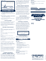
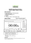
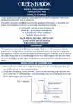
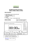
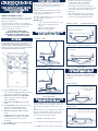
WIRING INSTRUCTIONS
LIGHT SENSITIVE LIGHT SWITCH
INSTALLATION/OPERATING
INSTRUCTIONS
MODEL NUMBER: T41D-C
Thank you for purchasing a quality security timer
from Greenbrook. Please read these instructions
fully prior to initial use.
Before attempting any installation work, turn off
the electrical supply at the main switch, fuse box
or consumer unit and for additional safety
remove the fuse.
ONLY SUITABLE for tungsten filament lamp
loads of 40 to 400 watts maximum, and low
energy (CFL)11W and above.
GreenBrook light switches cannot be used with
any other electronic products.
DO NOT USE •
In two way systems with dimmers or any
Every effort has been made to ensure that the
other switch containing electronic
guidance information on this sheet will enable the
circuitry.
installation of the security light switch to be
•
With fluorescent strip lights.
carried out safely and correctly.
•
With low voltage lighting.
IF IN DOUBT, INSTALLATION
WIRING INSTALLATION IN ONE
SHOULD BE MADE BY A QUALIFIED
WAY SWITCHED CIRCUIT
ELECTRICIAN IN ACCORDANCE WITH
CURRENT WIRING REGULATIONS.
IMPORTANT
4. Study the existing wiring arrangement;
compare to the ‘Before’ illustrations.
- if you find 3 wires at each switch
(excluding the earth wire) see diagram 3.
- if you find 5 wires at one switch and 3 wires
at the other (excluding the earth wire) see
diagram 5.
After establishing the appropriate wiring
method install the Security Light Switch as
per the corresponding ‘After’ illustration.
Diagram 3 - Before
YELLOW AND GREEN
3 Wires in both switches
Diagram 1 - Before
FOR EFFECTIVE OPERATION, THIS UNIT MUST BE
EXPOSED TO DIRECT DAYLIGHT AND SHOULD NOT
BE COVERED BY CURTAINS OR FURNISHINGS.
ALSO, IT SHOULD NOT BE SUBJECTED TO STRONG
STREET LIGHTING, AS THE LIGHT SENSOR CANNOT
DIFFERENTIATE BETWEEN DAY & NIGHT.
Diagram 4 - After
EARTHS MUST
REMAIN CONNECTED TO
Timer installed at live
wire end only
D
A
E
B
C
F
Diagram 2 - After
YELLOW AND GREEN
G
METAL BOX
WIRING INSTALLATION FOR
5 & 3 WIRE ARRANGEMENT
H
Diagrams 5 to 7 show various installations before
and after your Greenbrook security timer has
been fitted.
Diagram 5 - Before
A. FUSE CARRIER Pull out to replace
fuse (a special 3A BS646 20mm x 5mm,
this is not an ordinary 3amp fuse)
B. DARKNESS SENSITIVITY CONTROL
Allows switch to react to different
levels of darkness
C. DARKNESS SENSOR Monitors light
levels
D. PUSH ON/OFF Switch - Allows unit to
operate as ordinary light switch.
Activates even when lid is closed.
E. OVERRIDE SWITCH MAN: Manual
mode
AUTO: Automatic programme mode
F. TIME ON Allows selection of “ON”
periods up to 8 hours (in hourly
intervals)
G. RED NEON Lit when in automatic mode
H. RESET BUTTON
5 & 3 wire arrangement
Yellow & Green earths
must remain connected
to metal box
EARTHS MUST REMAIN CONNECTED TO
METAL BACK BOX
WIRING INSTALLATION IN TWO
WAY SWITCHED CIRCUIT
Before installing your security Light switch in a
two way circuit it is first necessary to determine
which method of wiring has been used in your
home.
The primary reason for doing this is to make sure
that the security switch is wired in such a way
that has a permanent live feed at all times in
order to power the electronic timer.
1. TURN OFF THE MAIN SUPPLY.
2. Loosen the two switch plates from the wall.
3. Do NOT disconnect any wires at this stage.
Diagram 6 - After
Light switch timer at 3 wire end
Yellow & Green earths must
remain connected to metal box
Diagram 7 - After
Light switch timer at 5 wire end
Yellow & Green earths must
remain connected to metal box
to automatic operation i.e. light switch works to
the preset programme), slide override switch
(E) so that AUTO position is showing. Red
neon (G) will be illuminated and the light will
switch on when the pre-set level of
darkness is reached.
PROBLEM 3
Light only operates correctly from one switch in a
two way circuit
SOLUTION
- The wiring is incorrect, consult a qualified
electrician.
MANUAL ON/OFF OPERATION
OPERATING INSTRUCTIONS
SETTING YOUR LIGHT SWITCH
a) Ensure light fitting(s) being controlled
have bulb(s) fitted, otherwise light switch will
not function.
b) After installation is complete, reconnect power
at the mains (remembering to replace the fuse
if removed for safety reasons).
c) Press reset button H with ball point pen and
hold for two seconds.
When all settings have been completed close
the front cover until it clicks into position
concealing the operating controls. The room
light(s) can be turned on and off by simply
pressing the top of the front cover. The position
of the override switch (E) does not affect this
operation.With the front cover closed, the red
neon (G) will be illuminated or in manual
mode when it will be off.To access the controls
again, grip the front cover with forefinger and
thumb either side and ease the cover forward.
PREPARING FOR OPERATION
STEP 1.
Slide the override switch E so that the automatic
position is showing, the red neon G will
illuminate.
STEP 2.
Ensure the room light is off, if necessary use the
push on/off switch (D).
STEP 3.
As darkness approaches monitor when the
light(s) come on.
a. If the light comes on too early i.e. still too light
outside, use a small screwdriver to turn the
darkness sensitivity control B slightly towards D
(anti-clockwise).
b. If the light comes on too late i.e. too dark
outside, use a small screwdriver to turn the
darkness sensitivity control B slightly towards L
(clockwise).Close the front cover until it clicks into
position concealing operation controls.
STEP 4.
For the next few days monitor the when the light
comes on. Fine adjustments to the darkness
sensitivity control B will ensure that the light
comes on when you want it to. To achieve the
desired on time, this may also take a few days of
adjustments.
AUTOMATIC OR MANUAL
CONTROL - OVERRIDE SWITCH
FALSE ACTIVATION
Someone standing against the light switch for
more than 30 seconds or a heavy thunderstorm
may result in early activation. When normal
light level is resumed, press the reset button
(H) for 2 seconds.
PLEASE KEEP THESE
INSTRUCTIONS SAFE FOR FUTURE
REFERENCE
CHANGING A LIGHTBULB
In the event of a lightbulb ‘blowing’ the light
switch will fail to work.Always disconnect the
power before replacing the light bulb by pulling
the fuse carrier (A) forward until the fuse is
fully visible. It may be necessary to replace the
fuse following the replacement of a lightbulb if
the light switch does not operate when the
carrier (A) is pushed back into position.
Replace the old fuse by pushing it upwards
from the slot in the base of the carrier.
Note: After replacing a lightbulb,
replacing a fuse or a mains power
failure, press the reset button (H)
for 2 seconds.
FUSE REPLACEMENT
Always replace the fuse with a BS646 rated
3amp fuse. A normal 3amp fuse will not fit.
TROUBLE SHOOTING
PROBLEM 1
Light will not switch on
SOLUTION
- Press reset button H.
- Check that bulb has not blown.
- Check wiring is correct.
- Check fuse, by withdrawing fuse carrier A,
incorrect wiring can blow the fuse.
- The required level of darkness has not Been
reached previously.
- Wait until dusk then adjust darkness sensor
C as described.
PROBLEM 2
Sufficient light is prevented from being
detected by darkness sensor C
SOLUTION
- Remove any soft furnishings or other
obstructions from proximity.
WEST ROAD . HARLOW
ESSEX . CM20 2BG . UK
[email protected]
WWW.GREENBROOK.CO.UK
Issue no: 701569
During those occasions when you are home early
and you do not want your light switch to operate
as set, slide the override switch E so that MAN
shows for manual operation. The light switch will
only operate via the push on/off switch (D), the
red neon (G) will not be illuminated.To revert back
Rated Voltage: 230V, AC 50Hz
Load:
Max 400W–Min 40W + most
Low Energy (CFL) 11W & above
Tungsten bulbs only
Integral 3 amp fuse
ALWAYS REPLACE WITH A SPECIAL
3AMP BS646 FUSE. (THIS IS NOT AN
ORDINARY 3AMP FUSE)
SETTING TIME ON
This sets the time your light remains on for. The
time on period can be set from a minimum of
1 hour to a maximum of 8 hours in 1 hour
increments. This is set by turning dial F (see first
diagram for reference) to the desired time i.e.
1,2,3,4,5,6,7 or 8 hours.
TECHNICAL DATA