1
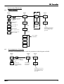
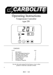
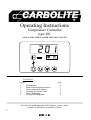
Operating Instructions
Temperature Controller
type 201
(APPLICABLE WHEN ALARM FEATURE IS IN USE)
CONTENTS
section
1
2
3
4
5
6
page
Description
Basic Operating Instructions
Overtemperature Option
Altering the Power Limit
User Calibration
Navigation Diagrams
1
3
5
5
6
7
See also the main manual for the furnace, oven or other
product to which the controller is fitted.
1
MC07 – 1.04
201 Controller
DESCRIPTION
1.1
201 Controller
1.2
The model 201 controller is made especially for Carbolite by Eurotherm, and shares many of the
features of the Eurotherm 2000 range, especially the model 2132. It is a digital instrument with
PID control algorithms. It is supplied as an integrated part of the control section of the oven or
furnace.
The 201 features:
- Easy use as a simple temperature controller, where on setting the required temperature the
controller immediately attempts to reach and maintain it.
- A ramp-to-setpoint feature, which may be used to limit the heating (or cooling).
- An alarm output which may be used in conjunction with a solid state relay for miscellaneous
control purposes.
The controller does not contain a real-time calendar, and is not subject to century-end date
problems.
Model 201 Overtemperature Controller
The 201 is optionally available as a dual unit containing the main controller and an
overtemperature controller. These two components share the same display and buttons, but are
otherwise independent.
The operational features in the overtemperature controller include:
- Easy setting of the overtemperature limit (setpoint);
- A visible alarm on overtemperature condition;
- A latching alarm output used to cut power to the heating elements; this alarm output can
also be used to power an optional audible alarm;
- 2-key alarm acknowledgement.
2
2
MC07
201 Controller
BASIC OPERATING INSTRUCTIONS
2.1
Furnace or Oven Controls
2.2
Most Carbolite products are fitted with an “Instrument Switch” which cuts off power to the
controller and other parts of the control circuit. See the instruction manual for the furnace or
oven for the overall operating instructions.
To operate the 201 there must be power to the furnace or oven, and the Instrument switch must
be on. If a time switch is included in the furnace or oven circuit, this must be in an On period.
The 201 – Operation
Note: on the 201 display
the letters m and w look
like n and u. In these
instructions the letters are
described as m and w.
2.3
When switched on, the controller lights up, goes through a short test routine, and then displays
the measured temperature and starts to control. The output light glows or flashes as heating
occurs.
The Page key allows access to parameter lists within the controller; most lists and parameters
are hidden and cannot be accessed by the operator because they contain factory-set parameters
which should not be changed.
A single press of the page key displays the temperature units, normally set to °C; further
presses reveal the lists indicated in the Navigation Diagram in section 6.
The Scroll key 4 allows access to the parameters within a list. Some parameters are displayonly; others may be altered by the operator. Some parameters only appear in appropriate
circumstances – for example, working setpoint does not appear if setpoint ramp rate is Off.
A single press of the scroll key 4 displays the temperature units; further presses reveal the
parameters in the current list indicated in the Navigation Diagram.
To return to the Home list at any time, press Page and Scroll 4 together, or wait for 45
seconds.
The Down T and Up S keys are used to alter the setpoint or other parameter values.
Basic Operation
2.4
Normally no operator action is required other than entering the setpoint, as the 201 starts to
control on being switched on, as described above.
Altering the Setpoint
With the display at “home”, showing the measured temperature, press Down T or Up S once to
display the setpoint; press again or hold down to adjust it. The display returns to the measured
temperature when no key is pressed for 0.5 seconds.
2.5
MC07
3
201 Controller
Stopping and Starting Control
It is possible to stop and start the controller without altering the setpoint. Press Scroll 4 until the
legend m-A (manual/auto) appears. In the 201, manual means “off” and auto means “on”. Press
Down T or Up S once to show the current on/off state: mAn for off, and Auto for on. Press T or
S to change between manual and auto (off and on) as required.
2.6
Altering the Ramp Rate
It is possible to limit the rate of heating by setting a ramp rate. Press Scroll 4 until the legend
SPrr (SetPoint ramp rate) is displayed. Use Down T or Up S to display and adjust the value.
The ramp rate sets the maximum rate of heating or cooling in degrees per minute. A value of OFF
cancels the ramp rate, allowing heating and cooling at the maximum rate. When this feature is in
use, there is a “working setpoint” which can be viewed at any time by scrolling to w.SP and
pressing T or S.
Fig 1 and fig 2 indicate the possible difference between running without and with a ramp-tosetpoint value (depending on the load and the value used).
3
4
MC07
201 Controller
OVERTEMPERATURE OPTION
This is only fitted when the overtemperature option is ordered. To identify whether it is fitted,
observe the controller panel: if it is fitted the overtemperature key and warning light are present.
The overtemperature key must be held depressed continuously while viewing or adjusting the
overtemperature controller. If the Overtemperature key is released, the display reverts to the
main controller.
With the key pressed the overtemperature setpoint is normally displayed. To alter the value, use
Down and Up. To view the measured temperature, press Scroll until PV (process variable) is
displayed, then press Down or Up. Keep the overtemperature key depressed during these
operations.
When an overtemperature condition is reached, the overtemperature warning light changes from
green to flashing red. To “accept” or “reset” this alarm condition, press the Overtemperature key
and the Page key together; the warning light changes to continuous red. Once the overtemperature condition is cleared (by the temperature falling), the light changes to green and
normal operation resumes.
4
ALTERING THE POWER LIMIT
4.1
Overview
4.2
Depending on the furnace or oven model the power limit parameter OP.Hi (Output High) may be
accessible or hidden.
For silicon carbide heated furnaces the parameter is accessible to allow for compensation for
element ageing (see the appropriate section in the furnace manual). In wire-heated chamber or
tube furnaces, reducing the power limit is a convenient method of improving control at low
temperatures, as outlined below.
The power limit may be set to zero to permit demonstration of the controls without heating.
In many models the power limit setting depends on the supply voltage; usually the furnace or
oven manual contains details: if in doubt, contact Carbolite for advice.
The power limit parameter does not apply to the overtemperature controller, if present.
Altering the value
4.3
Press Page until oP (output list) is displayed. Press Scroll 4 until OP.Hi (Output High) is
displayed. Press Down T or Up S once to display the value of OP.Hi and write down the value.
To alter the value, use Down T or Up S. Note that setting the value to zero prevents the furnace
or oven from heating.
Caution: Do not increase the power limit value to a value above the design level for the oven or
furnace model, or to a value above that correctly calculated for Silicon Carbide elements. The
heating elements could burn out, or other damage could be caused.
Control at Low Temperatures
If a product is to be used at temperatures much lower than its design maximum, control stability
can often be improved by reducing the power limit. Remember to make a record of the original
setting before altering the power limit.
Example: It is desired to run a 1200°C furnace at 300°C. The normal control settings can be
expected to cause excessive overshoot as the furnace reaches temperature. If the power limit
OP.Hi is normally set to 100%, try a setting of 40%. This should greatly reduce the overshoot.
(There is no firm calculation rule to get this example setting of 40% – experiment may be
required to achieve a good result. Avoid power limits below about 30% – control accuracy falls
off at such levels.)
5
MC07
5
201 Controller
USER CALIBRATION
The controller is calibrated for life at manufacture against known reference sources, but there
may be sensor errors or other system errors. User calibration allows compensation for such
errors, and the 201 allows for a user 2-point calibration. This setting is password protected to
avoid accidental alteration.
Page to iP, scroll to CAL.P, and use Up S to alter the password. The password is 3. If the correct
password is entered, the display shows PASS. Scroll to CAL and use T or S to observe the setting
FACt (factory values, as manufactured) or USEr (user values). Change to USEr.
NOTE: before checking the calibration of the controller, or of the complete system, remember to
reset the 201 to factory calibration values by setting the CAL.P parameter to FACt.
To enter a user calibration, scroll to each or the following parameters in turn and set the desired
values.
Pnt.L low temperature for which an offset is to be entered
OFS.L offset value for the low temperature
Pnt.H high temperature for which an offset is to be entered
OFS.H offset value for the high temperature
Example: the controller reads 3°C low at 400°C, and 5°C low at 1000°C. The parameter values
should be Pnt.L=400, OFS.L=3, Pnt.H=1000, OFS.H=5.
Negative or positive values can be entered: if the controller is reading high, negative offsets
would be appropriate.
Fig 4 gives a graphical representation of the 2-point calibration.
6
6
MC07
201 Controller
NAVIGATION DIAGRAMS
6.1
Main Controller
Home
List
Input
List
20.0
4
*C
Output
List
iP
oP
4
4
*C
measured temperature;
use T/S to access
setpoint
OP
output power,
read only
CAL.P
OP.Hi
w.SP
present only if
SPrr in use
m-A
manual/Auto
mAn=off, Auto-on
SPrr
setpoint ramp rate
OFF or value
4
enter
password
Access
List
power limit
setting, if
present
CAL
if user
calibration
Pnt.L
ACCS
4
codE
for factory access to
lists and parameters
not available to the
operator
user 2-point
calibration
OFS.L
Pnt.H
OFS.H
6.2
Overtemperature Controller
Hold the Overtemperature Key to make the parameters in this diagram available.
Home
List
20.0
4
*C
4
PV
*C
overtemperature
setpoint; use T/S to
alter
measured
temperature at
overtemperature
sensor
Input
List
Access
List
iP
ACCS
4
calibration
as for main
controller
4
codE
for factory access to
lists and parameters
not available to the
operator
MC07
7
For preventive maintenance, repair and calibration of all Furnace
and Oven products, please contact:
Thermal Engineering Services
Telephone: UK: 0845 3308035
Int: +44 1433 623335
Fax:
UK: 0845 3308036
Int: +44 1433 623336
Email:
[email protected]
MC07-1.04
1/3/01
201
Carbolite, Parsons Lane, Hope,
Hope Valley, S33 6RB, England.
Telephone: (01433) 620011
Int: +44 1433 620011
Facsimile: (01433) 621198
Int: +44 1433 621198
E-mail: [email protected]