1
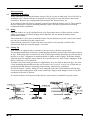
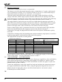
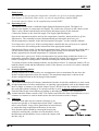
Installation, Operation &
Maintenance Instructions
1200°C Split Tube furnaces
types HST & VST
This manual is for the guidance of operators of the above Carbolite products and
should be read before the furnace is connected to the electricity supply.
CONTENTS
Section
1.0
2.0
3.0
4.0
5.0
6.0
7.0
8.0
9.0
page
Introduction
Installation
Operation
Maintenance
Repairs & Replacements
Fault Analysis
Circuit Diagrams
Fuses & Power Settings
Specifications
1
3
5
7
8
11
12
15
16
Manuals are supplied separately for the furnace controller
(and overtemperature controller when fitted).
Please read the controller manuals before operating the furnace.
1.0
MF13 – 3.31
HST, VST
INTRODUCTION
1.1
VST & HST models
The VST range comprises split tube furnaces designed for use vertically, with several mounting
options: the furnace may be provided with no stand; or with a wall bracket; or it may be fitted to
one of two stand designs – near and far.
The HST range uses the same insulated split case as the VST, fitted inside an outer case designed
for horizontal use – though this may be fitted to an L-stand which allows for both horizontal and
vertical use.
All models have a separate control box connected by electrical conduits or leads.
1.2
Voltage and Power Control
All models in this range, from March 2001, are supplied with heating elements designed for use
over the voltage range 200V-240V or 3-phase equivalents. The Carbolite control system
incorporates a “power limit” which effectively limits the voltage to 208V. It is most important that
any alternative system provided by the customer should be able to limit the power accordingly.
See sections 3.6 and 8.2.
1.3
Switches and Lights
Supply Light: when the furnace is connected to the electrical supply the
light in the adjacent switch glows
Heat Switch: the switch disconnects power to the heating elements; unless
this switch is off there is a danger of electric shock when inserting objects
into the furnace
Heat Light: the adjacent light glows or flashes to indicate that power is
being supplied to the elements
1.4
Warning Symbols
DANGER of electrical shock– read any warning printed by this symbol.
DANGER – hot surface. Read any warning printed by this symbol.
WARNING: all surfaces of a furnace may be hot.
2.0
2
DANGER – read any warning printed by this symbol.
MF13
HST, VST
INSTALLATION
2.1
Unpacking & Handling
When unpacking or moving the furnace always lift it by its case or main body. Never lift it by its
insulation or by a fitted work tube. If possible use two people to carry the furnace and remote
control box. Remove any packing material from inside the furnace before use.
If an optional or special stand is separately supplied, assemble the furnace on to it. These models
may be supplied for customer mounting and may require customer preparation of mounting
components before installation.
2.2
Siting
Place the furnace in a well ventilated room, away from other sources of heat, and on a surface
which is resistant to accidental spillage of hot materials. Do not mount the furnace on an
inflammable surface.
Ensure that there is free space around the furnace. Do not obstruct any of the vents in the control
box: they are needed to keep the controls cool.
Ensure that the control box is placed in such a way that it can be quickly switched off or
disconnected from the electrical supply - see below.
2.3
Setting Up
If the furnace is supplied with a work tube or any accessories fit these into position.
For optimum temperature uniformity, insulating plugs should be placed in the tube ends as shown
in fig.1. With a long inner work tube, the stem of the plug assembly should line up with the end of
the tube as in fig.2. Alignment of radiation shields is similar to that of plugs. With these models,
split end plugs are supplied; unless ordered for a specific tube size, these require shaping to fit the
tube or work piece: use a round file.
If stainless steel seals with gas inlets are supplied they are to be fitted as shown in fig.3; the stem
of any insulating plug should touch the seal. Stainless steel seals for vertical use: a hook and eye
arrangement holds the upper insulating plug assembly; alternatively a gland nut.
Horizontal models: if heavy fittings are to be clamped to the end of an extended work tube they
can increase the bending stress at the centre of the tube. Support such fittings in such a way that
expansion of the tube is allowed.
If a metal work tube is being used in the furnace, ensure that it is earthed for operator safety.
MF13
3
HST, VST
2.4
Electrical Connections
Connection by a qualified electrician is recommended.
The furnaces covered by this manual normally require a single phase A.C. supply, which may be
Live to Neutral non-reversible, Live to Neutral reversible or Live to Live. Some models may be
ordered for 3-phase use (and if so, are “universal” – see section 2.5).
Check the furnace rating label before connection. The supply voltage should agree with the
voltage on the label, and the supply capacity should be sufficient for the amperage on the label.
If the actual supply is not the same as the voltage on the label, then the controller power limit may
need to be adjusted: set the Heater Switch to off, connect the furnace and see section 3.6.
The supply should be fused at the next size equal to or higher than the amperage on the label. A
table of the most common fuse ratings is also given in section 8.1 of this manual. Where a supply
cable is present there are internal supply fuses: customer fusing is preferred but not essential.
Furnace with supply cable: either wire directly to an isolator or fit with a line plug.
Furnace without supply cable: a permanent connection to a fused and isolated supply should be
made to the internal terminals after temporary removal of the furnace back panel.
Connection by line plug: the plug should be within reach of the operator, and should be quickly
removable.
Connection to isolating switch: this should operate on both conductors (single phase) or on all live
conductors (three phase), and should be within reach of the operator.
The supply MUST incorporate an earth (ground).
CONNECTION DETAILS
Supply
Terminal label
L
1-phase
N
PE
supply
Terminal label
L1
2- or 3-phase
L2
L3
N
PE
Cable colour
Brown
Blue
Green/Yellow
Cable colour
Black
Black
Black
Light Blue
Green/Yellow
supply type
Live-Neutral
Reversible or Live-Live
To live
to either power conductor
To neutral
to the other power conductor
To earth (ground) to earth (ground)
to phase 1
to phase 2
to phase 3 except 2-phase
to neutral except delta
to earth (ground)
Do not connect a furnace ordered for three phase use to a single phase supply or to the wrong type
of three phase supply – except as indicated in sections 2.5 and 7.7.
2.5
“Universal Wiring”
(year 2000 onwards)
When (and only when) ordered for 3-phase use these furnaces are supplied in a form in which they
can be easily rewired between 1-phase and 3-phase supplies. This applies to 3-phase+N and 3phase delta in the ranges 380/220V–415/240V and 200-240V, but does not apply to 3-phase star
without neutral (e.g 380V or 440V).
To alter the configuration, remove the control box back panel and alter the connections between
the supply terminal block and the EMC filters, using the appropriate diagram from section 7.7.
Models ordered for single phase only are not affected and cannot be converted to 3-phase.
If in doubt, please consult Carbolite.
3.0
4
MF13
HST, VST
OPERATION
The instructions for operating the temperature controller are given in a separate manual.
If the furnace is fitted with a time switch, see also the supplementary manual MS03.
If cascade control is fitted, see the supplementary manual MS07.
3.1
Operating Cycle
The furnace is fitted with a combined Supply light and Instrument switch. The light is on
whenever the furnace is connected to the supply. The switch cuts off power to the control circuit.
There is also a Heater switch which can be used to disconnect power to the elements.
Connect the furnace to the electrical supply. The Supply light should glow .
Operate the instrument switch to activate the temperature controller; the O position is off, the
I position on. The controller becomes illuminated and goes through a short test cycle.
Set the temperature controller to the desired setpoint or program - see the controller manual.
Overtemperature option only. If the overtemperature controller has not yet been set as required,
set it and activate it according to the instructions in the appropriate manual.
Switch on the Heater switch, located on the instrument panel. Unless a time switch is fitted and is
off, the furnace starts to heat up. The Heat light(s) glow steadily at first and then flash as the
furnace approaches the desired temperature or a program setpoint.
Overtemperature option only. If the overtemperature trip operates then an indicator in the overtemperature controller flashes, and the heating elements are isolated. Find and correct the cause
before resetting the overtemperature controller according the instructions supplied.
To switch off power to the heating elements, use the Heater Switch. To switch the furnace off, use
both the Heater switch and the Instrument switch. If the furnace is to be left off, isolate it from the
electrical supply.
3.2
General Operating Advice
Heating element life is shortened by use at temperatures close to maximum. Do not leave the
furnace at high temperature when not required. The maximum temperature is shown on the
furnace rating label and on the back page of this manual.
3.3
Operator Safety
The ceramic materials used in furnace manufacture become electrically conductive to some extent
at high temperatures. In these models there are partially exposed heating coils in the chamber and
there is danger of contact even with the furnace closed. DO NOT use any conductive tools within
the work tube without isolating it. If a metal work tube is used, it must be earthed (grounded).
Switch off the Heater switch whenever loading or unloading the furnace. The elements are
isolated when the Heater switch is OFF. This switch cuts both sides of the circuit directly or via a
contactor (a contactor is used in models where the rated current exceeds 16 Amps).
3.4
Tube Life
A ceramic work tube may be cracked if workpieces are
inserted too quickly or at temperatures below 900°C (when the
tube is more brittle). Large pieces should also be heated slowly
to ensure that large temperature differences do not arise.
Poor thermal contact should be encouraged between the
workpiece and the tube; crucibles or boats should be of low
thermal mass and should have feet to reduce the contact with
the tube (fig. 4).
MF13
5
HST, VST
Do not set too high a heating rate. Large diameter tubes are more susceptible to thermal shock
than smaller. Tubes which extend beyond the heated part of the furnace are more at risk. A general
rule for maximum heating rate is 400/internal diameter (°C/min); for 75mm i/d tubes this comes to
5°C per minute. The controller can be set to limit the heating rate.
3.5
Pressure
Work tubes are not able to accept high internal pressure. When gas seals or similar fittings are in
use, the gas pressure should be restricted to a maximum of 0.2 bar (3 psi). A pressure of about half
of that should normally be sufficient to achieve the desired flow rate. The customer must ensure
that the exhaust path from the tube is not blocked, so that excess pressure does not occur.
3.6
Power Adjustment
The furnace control system incorporates electronic power limiting. The power limit parameter
OP.Hi is accessible to the operator, and can be used to adjust the furnace to the actual supply
voltage.
The models covered by this manual (March 2001 onwards) are designed for use over the range of
voltages 200V-250V (or, if ordered, 100V-125V), and the power limit parameter is set
accordingly. These models may be relocated to a different voltage within the range: the power
limit should be reset to match the voltage. See section 8.2.
To alter the power limit
Set the Heater Switch to Off to prevent heating while adjusting the power limit.
Press Page until oP (output list) is displayed. Press Scroll 4 until OP.Hi (Output High) is
displayed. Press Down T or Up S once to display the value of OP.Hi (it is good practice to write
down the original value). To alter the parameter to the desired value use Down T or Up S.
A power setting of zero prevents the furnace from heating: useful for demonstrating the controls
without taking power.
Do not increase the power limit simply “to get more power”. The elements could burn out, or a
fuse could blow.
3.7
Running at Low Temperatures
The power limit may be adjusted to a low level to achieve better control when running the furnace
at a low temperature. No hard and fast rules can be given, but, as an example, to run at
temperatures only up to 600°C try a power limit of 50%. Control stability may fall off again if a
setting below about 40% is used.
Before changing the power limit, record its factory setting for possible future use.
4.0
6
MF13
HST, VST
MAINTENANCE
4.1
General Maintenance
No routine maintenance is required. The outer surfaces may be cleaned with a damp cloth. Do not
allow water to enter the case, chamber or control box. Do not clean with organic solvents.
4.2
Calibration
After prolonged use the controller and/or thermocouple could require recalibration. This would be
important for processes which require accurate temperature readings or which use the furnace
close to its maximum temperature. A quick check using an independent thermocouple and
temperature indicator should be made from time to time to determine whether full calibration is
required. These items can be supplied by Carbolite.
Depending on the controller, the controller manual may contain calibration instructions.
4.3
After Sales Service
Carbolite’s service division (Thermal Engineering Services) has a team of Service Engineers
capable of repair, calibration and preventive maintenance of furnace and oven products at our
customers’ premises throughout the world. We also sell spares by mail order. A telephone call or
fax often enables a fault to be diagnosed and the necessary spare part despatched.
Each furnace has its own record card at Carbolite. In all correspondence please quote the serial
number, model type and voltage given on the rating label of the furnace. The serial number and
model type are also given on the front of this booklet when supplied with a furnace.
To contact Thermal Engineering Services or Carbolite see the back page of this manual.
4.4
Recommended Spares Kits
Carbolite can supply individual spares, or a kit of the items most likely to be required. Ordering a
kit in advance can save time in the event of a breakdown. Each kit comprises one thermocouple,
one solid state relay, and two heating elements (models --/900: 2 of each length).
When ordering spares please quote the model details as requested above.
5.0
MF13
7
HST, VST
REPAIRS & REPLACEMENTS
5.1
Safety Warning – Disconnection from Supply
Always ensure that the furnace is disconnected from the supply before repair work is
carried out.
5.2
Safety Warning - Refractory Fibrous Insulation
This furnace contains refractory fibres in its thermal insulation. These materials may
be in the form of fibre blanket or felt, vacuum formed board or shapes, mineral wool
slab or loose fill fibre.
Normal use of the furnace does not result in any significant level of airborne dust from these
materials, but much higher levels may be encountered during maintenance or repair.
Whilst there is no evidence of any long term health hazards, we strongly recommend that safety
precautions are taken whenever the materials are handled.
Exposure to dust from fibre which has been used at high temperatures may cause
respiratory disease.
When handling fibre always use an approved mask, eye protection, gloves and long
sleeved clothing.
Avoid breaking up waste material. Dispose of waste fibre in sealed containers.
After handling rinse exposed skin with water before washing gently with soap (not
detergent). Wash work clothing separately.
Before commencing any major repairs we recommend reference to the European Ceramic Fibre
Industry Association Bulletin No. 11 and the UK Health and Safety Executive Guidance Note
EH46.
We can provide further information on request. Alternatively our service division can quote for
any repairs to be carried out at your premises or ours.
5.3
Temperature Controller Replacement
201. This controller is fitted to the back of the control panel; in many models this can be separated
from the base by removal of two screws.
Before handling the controller: wear an anti-static wrist strap or otherwise avoid any possibility
of damage to the unit by static electricity.
Refer to the detailed instructions supplied with the replacement controller.
2132, 2416, 2408 etc. Ease apart the two lugs at the side; grip the instrument and withdraw it from
its sleeve; push in the replacement.
5.4
Solid-state Relay Replacement
Disconnect the furnace from the supply and remove the furnace back panel from control box.
Make a note of how the wires are connected to the solid state relay, and disconnect them.
Remove the solid state relay from the base panel or aluminium plate.
Replace and reconnect the solid state relay ensuring that the heat-conducting thermal pad is
sandwiched between the relay and the base panel or aluminium plate. Alternatively a thin layer of
white, heat-conducting silicon paste may be applied between the new relay and the plate.
The new solid state relay contains a built-in MOV which protects it from short periods of excess
voltage. If the old relay had a separate disc-shaped "MOV" connected between the high voltage
terminals of the old relay, discard the old MOV.
Replace the removed panel.
8
MF13
HST, VST
5.5
Thermocouple Replacement
The coverings and guards which must be removed to gain access to the thermocouple depend on
the model, and any mounting options or fittings. Study the furnace layout and consult Carbolite if
in doubt.
Disconnect the furnace from the supply, and remove covers and guards as necessary.
Make a note of the thermocouple connections. The negative leg of the thermocouple is marked
blue. Compensating cable colour codings are:
negative
positive (type N)
white
pink
Disconnect the thermocouple from its terminal block.
Withdraw the thermocouple from its sheath (the narrow-bore built-in tube) and remove any
broken bits of thermocouple.
Bend the new thermocouple carefully to match the shape of the original (working from the
terminal end). Should the length differ from that of the original this is usually not important
provided that the thermocouple tip is within a tube diameter's distance from the furnace centre; for
models with an even number of element modules, the tip should be a quarter to a third of one
element’s length from the furnace centre.
Insert the new thermocouple into position, restoring any removed porcelain spacers, and ensuring
correct polarity.
Re-assemble the furnace.
5.6
Fuse Replacement
Fuses are marked on the circuit diagram (section 7.0) with type codes, e.g. F1, F2. A list of the
correct fuses is given in section 8.1. Depending on model and voltage, the different fuse types may
or may not be fitted.
If any fuse has failed, it is advisable for an electrician to check the internal circuits.
Replace any failed fuses with the correct type. For safety reasons do not fit larger capacity fuses
without first consulting Carbolite.
The fuses are near the cable entry point, and access is by removal of the back panel of the base or
control box.
5.7
MF13
9
HST, VST
Element Replacement
Please see safety note 5.2 - please wear a face mask.
HST, and VST with far hinge: Remove the three screws from each end and lift out the half-circular
insulation assembly.
Make a plan of all the cable connections and disconnect the cables.
Remove the thermocouple(s) by withdrawing them from the sheaths built into the elements.
Remove the plates through which the element tails are located. Remove the keep plates from each
side of the insulation assembly.
Lift out the element to be replaced; save any insulation sleeves for possible reuse.
Bend or cut the new element tails as necessary, and fit any insulation sleeves; feed the tails
through and fit the element into place.
Refit the keep plates on each side. Refit the tail termination plates, ensuring that the element tails
do not touch any metal parts. Refit the thermocouple(s).
Connect all the wiring according to the plan previously made, and complete the reassembly of the
furnace.
Check that the furnace is controlling properly to rule out the possibility that the element failed
because of a fault in the control system.
HST & VST 12/--/200
HST & VST 12/--/300
HST & VST 12/--/400
HST & VST 12/--/500
HST & VST 12/--/600
HST & VST 12/--/900
HST & VST Elements
each element is a half-cylinder
200-240V 1 pair of 200mm
100-120V
elements in series
200-240V 2 pairs of 150mm
100-120V
elements in parallel,
each pair in series
200-240V 2 pairs of 200mm
100-120V
elements in parallel,
each pair in series
100-120V
200-240V 2 pairs of 150mm
elements in parallel,
and 1 pair of 200mm
elements in parallel,
each pair in series
200-240V 3 pairs of 200mm
100-120V
elements in parallel,
each pair in series
100-120V
200-240V 2 pairs of 150mm
elements in parallel,
and 3 pairs of 200mm
elements in parallel;
each pair in series
1 pair of 200mm
elements in parallel
2 pairs of 150mm
elements in parallel
2 pairs of 200mm
elements in parallel
2 pairs of 150mm and
1 pair of 200mm
elements in parallel
3 pairs of 200mm
elements in parallel
2 pairs of 150mm and
3 pairs of 200mm
elements in parallel
Wherever two different sizes of elements are fitted, the 150mm elements are at the ends and the
200mm elements in the centre.
6.0
10
MF13
HST, VST
FAULT ANALYSIS
A. Furnace Does Not Heat Up
1. The HEAT light Æ The heating
element has failed
is ON
Æ Check also that the SSR is working
correctly
2.
The controller
shows a very high
temperature or a
code such as S.br
Æ The thermocouple has broken or has a
wiring fault
The controller
shows a low
temperature
Æ The door switch(es) (if fitted) may be
faulty or need adjustment
The HEAT light
is OFF
Æ The contactor (if fitted) may be faulty
Æ The SSR could be failing to switch on due
to internal failure, faulty logic wiring from
the controller, or faulty controller
There are no
lights glowing
on the
controller
B.
1.
Furnace Overheats
The HEAT light Æ
goes OFF with
the instrument
switch
Æ
Æ The SUPPLY
light is ON
Æ The controller may be
faulty or not receiving a
supply due to a faulty
switch or a wiring fault
Æ The SUPPLY
light is OFF
Æ Check the supply fuses and
any fuses in the furnace
control compartment
The controller
shows a very high
temperature
Æ The controller is faulty
The controller
shows a low
temperature
Æ The thermocouple may have been shorted
out or may have been moved out of the
heating chamber
Æ The thermocouple may be mounted the
wrong way round
Æ The controller may be faulty
2.
The HEAT light
does not go off
with the
instrument
switch
Æ The SSR has failed
“ON”
Æ Check for an accidental wiring fault which
could have overloaded the SSR
7.0
MF13
11
HST, VST
CIRCUIT DIAGRAMS
Safety Switches type A: a 2-pole Heater Switch is fitted directly in the element circuit in models
up to 16A rating. Two “door switches” are also fitted in the element circuit up to 25A rating.
Safety Switch type B: a Heater Switch is fitted into the contactor coil circuit in models over 16A.
A door switch is fitted into the contactor coil circuit over 25A rating.
Single Phase
7.1
N
L
PE
F1
Filter
(if fitted)
F3
safety
switches A
contactor
if fitted
F2
Supply light
Instrument Switch
overtemp.
controller
heat
on
coil
safety
switch B
if fitted
thermocouple
e
l
e
m
e
n
t
(s)
F3
SSR
temperature
controller
thermocouple
7.2
2-phase with neutral
As 3-phase, with phase L3 not present, and with two SSRs and element circuits. In models up to
25A safety switches type A are fitted in the L1 and L2 circuits instead of type B in the contactor
coil circuit.
3-phase with neutral
7.3
N
Filter (if fitted)
L3
L2
L1
PE
F1
contactor
F2
Supply light &
Instrument Switch
safety
switch
overtemp.
controller
heat
on
coil
if fitted
thermocouple
temperature
controller
e
l
e
m
e
n
t
(s)
heat
on
e
l
e
m
e
n
t
(s)
heat
on
e
l
e
m
e
n
t
(s)
F3
SSR
F3
SSR
thermocouple
F3
SSR
note on 3-phase: depending on filter(s) fitted, there may be 3
separate neutral wires from the elements to the neutral supply.
12
MF13
HST, VST
7.4
3-phase without neutral (delta)
Filter (if fitted)
L3
L2
L1
F1
contactor
F2
PE
F3
Supply light &
Instrument Switch
heat
on
coil
safety
switch
overtemp.
controller
if fitted
thermocouple
temperature
controller
F3
heat
on
F3
e
l
e
m
e
n
t
(s)
heat
on
e
l
e
m
e
n
t
(s)
F3
SSR
F3
SSR
thermocouple
7.5
e
l
e
m
e
n
t
(s)
F3
SSR
3-phase without neutral (star – e.g. 380 to 415V)
Filter (if fitted)
L3
L2
L1
F1
contactor
F2
PE
transformer
F2
Supply light &
Instrument Switch
heat
on
coil
safety
switch
overtemp.
controller
temperature
controller
47k
if fitted
thermocouple
e
l
e
m
e
n
t
(s)
heat
on
47k
e
l
e
m
e
n
t
(s)
heat
on
e
l
e
m
e
n
t
(s)
47k
F3
SSR
F3
SSR
thermocouple
F3
SSR
Note: in this configuration the fuses F2 on the supply side of the transformer may be
GEC Safeclip, not 32 x 6mm glass as stated in section 8.1.
7.6
Higher Voltages (e.g. 254V; 440V, 480V 3-phase)
The diagram above (7.5) normally applies, with neutral (if present) not being used.
For single phase models of 254V or above, diagram 7.1 applies except that a control circuit
transformer is included as in diagram 7.5.
MF13
13
HST, VST
7.7
3-phase “universal” wiring
Filters (if fitted)
N
L
N
L
N
L
F1
F2
F3
Supply light &
Instrument Switch
safety
switch
overtemp.
controller
temperature
controller
Contactors
(2 or 3)
coil
heat
on
coil
if fitted
thermocouple
e
l
e
m
e
n
t
(s)
F3
heat
on
e
l
e
m
e
n
t
(s)
F3
heat
on
e
l
e
m
e
n
t
(s)
F3
SSR
F3
SSR
thermocouple
F3
SSR
Fuses F1 are always present in this wiring design.
Fuses F2 could be absent in some circumstances, if the circuit does not exceed 10A.
Fuses F3 are present if the circuit exceeds 25A, but otherwise are usually absent.
3-phase delta
3-phase + neutral
Supply
Terminals
L1
Fuses or
EMC filters
Supply
Terminals
N
L
N
L1
Circuit no. 1
L
L2
N
L
N
Circuit no. 2
Not
used
N
L3
L
N
N
PE
L
Circuit no. 3
PE
Circuit no. 1
L2
N
L3
Fuses or
EMC filters
Circuit no. 2
Circuit no. 3
L
1-phase
Supply
Terminals
A model made to this diagram can be
converted by the customer between the
following supply voltages:
between 3-phase + neutral in the range
380/220V – 415/240V
and
3-phase delta in the range
200V – 240V
and
single phase in the range
200V – 240V
8.0
14
L1
Fuses or
EMC filters
N
L
Not
used
Circuit no. 1
L2
N
L3
L
N
N
PE
L
Circuit no. 2
Circuit no. 3
MF13
HST, VST
FUSES & POWER SETTINGS
8.1
Fuses
F1-F3: Refer to the circuit diagrams.
F1
F2
F3
Fitted if supply cable fitted.
Fitted on board to some types of EMC filter.
Internal
supply
fuses
Auxiliary
circuit
fuses
Fitted on board to some types of EMC filter.
May be omitted up to 25Amp/phase supply
rating.
Heat Light
fuses
May be omitted up to 25 Amp/phase supply
rating.
Customer
fuses
Required if no supply cable fitted.
Recommended if cable fitted.
Model
(from March 2001)
phases
Volts
on-board and up to 16 Amps:
32mm x 6mm type F
other: GEC Safeclip
2 Amps glass type F
On board: 20mm x 5mm
Other: 32mm x 6mm
2 Amps glass type F
32mm x 6mm
See rating label for amperage;
see table below for fuse rating.
Supply Fuse
Rating
Volts
Supply Fuse
Rating
HST & VST 12/--/200 1-phase
200-240
5A
110-120
HST & VST 12/--/300 1-phase
200-240
10A
110-120
HST & VST 12/--/400 1-phase
200-240
10A
110-120
HST & VST 12/--/500 1-phase
200-240
12.5A
110-120
HST & VST 12/--/500 3-phase + N 380/220-415/240 5A
HST & VST 12/--/500 3-phase delta 200-240
10A
HST & VST 12/--/600 1-phase
200-240
15-16A **
HST & VST 12/--/600 3-phase + N 380/220-415/240 5A
HST & VST 12/--/600 3-phase delta 200-240
10A
HST & VST 12/--/900 1-phase
200-240
25A
HST & VST 12/--/900 3-phase + N 380/220-415/240 10A
HST & VST 12/--/900 3-phase delta 220-240
15A
Other models or voltages: check the rating label for details of the supply.
Before March 2001 – please check with Carbolite if in doubt
8.2
10A
15-16A
20A
25A
Power Settings
The standard power limit settings (parameter OP.Hi) are as follows:
Volts:
HST or VST 12/-before March 2001 – all models
from March 2001 **
100V
200V
208V
100
100
100
100
110V
220V
380V
100
89
230V
400V
100
82
120V
240V
415V
100
75
127V
254V
440V
89
67
See section 3.6 for further detail.
** if you have specially ordered model --/600 for use in UK on a 13A supply, then the power limit
is 100% and the amps rating is 12.5A; please check your rating label.
MF13
15
9.0
MF13 – 3.31
SPECIFICATIONS
Carbolite reserves the right to change specifications without notice.
9.1
Models Covered by this Manual
Heated Net 1
Work
Work
Length Weight
Tube
Tube
Length
Bore
(°C)
(kW)
(mm)
(mm)
(mm)
(kg)
Split Tube furnaces heated by resistance wire moulded in refractory fibre
Horizontal Models in an opening case
HST 12/--/200
1200°C
1.0
25-100
350200
26
HST 12/--/300
1200°C
1.5
25-100
450400
29
HST 12/--/400
1200°C
2.0
25-100
550400
32
HST 12/--/500
1200°C
2.0
25-100
550400
37
HST 12/--/600
1200°C
3.0
25-100
750600
41
HST 12/--/900
1200°C
4.5
20-100
1050900
60
Vertical Models with a variety of stand and fixing options
VST 12/--/200
1200°C
1.0
25-100
350200
25
VST 12/--/300
1200°C
1.5
25-100
450400
28
VST 12/--/400
1200°C
2.0
25-100
550400
30
VST 12/--/500
1200°C
2.0
25-100
550400
33
VST 12/--/600
1200°C
3.0
25-100
750600
35
VST 12/--/900
1200°C
4.5
20-100
1050900
60
also models based on the above, but of other lengths, supplied to special order
MODEL
note 1:
9.2
Max.
Temp.
Max.
Power
Weights are approximate and do not include fittings or vertical stands.
Environment
The furnaces contain electrical parts and should be stored and used in indoor conditions as
follows:
temperature:
5°C - 40°C
relative humidity:
maximum 80% up to 31°C decreasing linearly to 50% at 40°C
The products covered in this manual are only a small part of the wide range of
ovens, chamber furnaces and tube furnaces manufactured by Carbolite for
laboratory and industrial use. For further details of our standard or custom built
products please contact us at the address below, or ask your nearest stockist.
For preventive maintenance, repair and calibration of all Furnace
and Oven products, please contact:
Keison Products
Telephone: UK: 01245 600560
Fax:
UK: 01245 600030
Email:
[email protected]
MF21-3.03
4/10/00
Int: +44 1245 600560
Int: +44 1245 600030
CR
Keison, P.O. Box 2124,
Chelmsford, CM1 3UP, England.
Telephone: (01245) 600560
Int: +44 1245 600560
Facsimile: (01245) 600030
Int: +44 1245 600030
E-mail: [email protected]