1
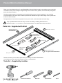
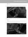
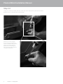
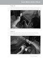
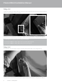
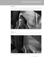
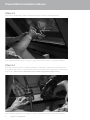
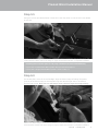
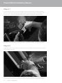
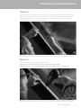
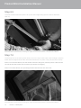
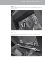
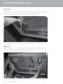
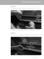
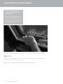
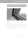
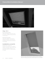
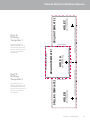
neo™ Steel
Pleated Blind Installation Manual
Issue 01
NSBL-PL-001INST-A
| January 2014
Pleated Blind Installation Manual
Thank you for purchasing the neo™ Steel Pleated Blind, please follow this step-by-step guide to ensure the blind
is installed correctly. If the rooflight’s integral linings have not been factory painted, we recommend painting them
before the blind is installed.
This blind system requires a reasonable level of practical skill to ensure correct installation. If you would like
on-site assistance, we have a team of trained professionals available through our blind fitting service, please call
01993 774 446 for details.
Take precautions to remove dirt and grease from any tools used, as the blind fabric will mark easily.
Parts
list - Supplied with blind
Parts!
Only a qualified electrician should carry out work uninstalling / installing electrical motors
(detailed in steps 1.0, 11.0 and 12.0), ensuring they adhere to any applicable safety precautions.
list - Supplied with blind
H
hand blind channel Parts list -Right
Supplied
with blind
only
supplied with
G
Dual Pleated blinds
Right hand blind channel only supplied with
Dual Pleated blinds
G
A
Right hand blind channel only supplied with
Dual Pleated blinds
G
A
Self tapping screws
B
Self tapping screws
I
Drilling Template 2 supplied on
back cover
B
C
Drilling templateCill
1 -unit clips
supplied on back cover
of installation guide
A C
D
Drilling template 1 Cill unit clips
supplied on back cover
of installation guide
B
C D
Drilling Template 2 Self tapping screws
supplied on
Blind system - Cill unit
back cover
I
Blind system - Cill unit
I
Blind system - Head unit
H
Blind system - Head unit
Head unit clips
Head unit clips
Cill unit clips
E
E
H
Drilling template 1 supplied on back cover
of installation guide
Blind system - Head unit
D
Head unit clips
F
F
Drilling Template 2 supplied on
back cover
E
Left hand blind channel only supplied with Dual Pleated blinds
Left hand blind channel only supplied with Dual Pleated blinds
F
Left hand blind channel only supplied with Dual Pleated blinds
Blind system - Cill unit
Please check that you have all the parts before proceeding to install the Pleated Blind.
If you believe any items are missing please call us on 01993 833108.
Tools list - Supplied by installer
Tools list - Supplied by installer
Tools list - Supplied by installer
Pozi-drive Screwdriver
2
Issue 01 | January 2014
Steel Rule
Tape Measure
Pencil
Pleated Blind Installation Manual
Step 1.0
At the cill of the Rooflight, align the bottom edge of Drilling Template 1 (Hole A) to the bottom
edge of the integral Rooflight lining and abut the left side of the template to the left jamb lining.
Drill through Hole A. Note: Do not drill deeper than 10mm through the integral lining.
Please note: these images do not show a complete roof window installation with painted linings and
internal finishes. Please refer to the image on page 18 which demonstrates a completed installation.
Step 1.1
Align the bottom edge of Drilling Template 1 (Hole A) to the bottom edge of the integral lining
and abut the right side of the template to the right jamb lining. Drill through Hole A. Note: Do
not drill deeper than 10mm through the integral lining.
Please note: these images do not show a complete roof window installation with painted linings and
internal finishes. Please refer to the image on page 18 which demonstrates a completed installation.
Issue 01 | January 2014
3
Pleated Blind Installation Manual
Step 2.0
Using the screws provided (Part B), screw two of the clips (Part C) into the two holes
drilled in step 2. Orientate the clip as shown.
Please note: these images
do not show a complete roof
window installation with painted
linings and internal finishes.
Please refer to the image on
page 18 which demonstrates a
completed installation.
4
Issue 01 | January 2014
Pleated Blind Installation Manual
Step 3.0
At the head of the Rooflight, align the bottom edge of Drilling Template 1 (Hole A) to the bottom
edge of the integral Rooflight lining and abut the right side of the template to the left jamb lining.
Drill through Hole A. Note: Do not drill deeper than 10mm through the integral lining.
Please note: these images do not show a complete roof window installation with painted linings and
internal finishes. Please refer to the image on page 18 which demonstrates a completed installation.
Step 3.1
Align the bottom edge of Drilling Template 1 (Hole A) to the bottom edge of the integral
Rooflight lining and abut the left side of the template to the right jamb lining. Drill through
Hole A. Note: Do not drill deeper than 10mm through the integral lining.
Please note: these images do not show a complete roof window installation with painted linings and
internal finishes. Please refer to the image on page 18 which demonstrates a completed installation.
Issue 01 | January 2014
5
Pleated Blind Installation Manual
Step 4.0
Using the screws provided (Part B), screw two of the clips (Part D) into the two holes drilled in
step 3.0. Orientate the clips as shown.
Please note: these images do not show a complete roof window installation with painted linings and
internal finishes. Please refer to the image on page 18 which demonstrates a completed installation.
Installing extra support clips for larger Rooflights.
If you have a total of 8 clips (Parts C & D) proceed with step 5.0.
If you have a total of 4 clips (Parts C & D) move to step 6.0.
Step 5.0
At the head of the Rooflight, mark a centre line along the width of the integral lining.
Please note: these images do not show a complete roof window installation with painted linings and
internal finishes. Please refer to the image on page 18 which demonstrates a completed installation.
6
Issue 01 | January 2014
Pleated Blind Installation Manual
Step 5.1
Align the centre line shown on drilling template 2 (Hole C & D) with the line marked in step 5.0.
Position the arrows on the template at the bottom edge of the integral lining. Drill through holes
B & C. Note: Do not drill deeper than 10mm through the integral lining.
Please note: these images do not show a complete roof window installation with painted linings and
internal finishes. Please refer to the image on page 18 which demonstrates a completed installation.
Step 5.2
Using the screws provided (Part B), screw two of the clips (Part D) into the two holes drilled
in step 5.1.
Please note: these images do not show a complete roof window installation with painted linings and
internal finishes. Please refer to the image on page 18 which demonstrates a completed installation.
Issue 01 | January 2014
7
Pleated Blind Installation Manual
Step 5.3
At the cill of the Rooflight, mark a centre line along the width of the integral lining.
Please note: these images do not show a complete roof window installation with painted linings and
internal finishes. Please refer to the image on page 18 which demonstrates a completed installation.
Step 5.4
Align the centre line shown on Drilling Template 2 (Hole B & C) with the line marked in step
5.3. Position the arrows on the template at the bottom edge of the integral lining. Drill through
holes B & C. Note: Do not drill deeper than 10mm through the integral lining.
Please note: these images do not show a complete roof window installation with painted linings and
internal finishes. Please refer to the image on page 18 which demonstrates a completed installation.
8
Issue 01 | January 2014
Pleated Blind Installation Manual
Step 5.5
Using the screws provided (Part B), screw two of the clips (Part C) into the two holes drilled
in step 5.4.
Please note: these images do not show a complete roof window installation with painted linings and
internal finishes. Please refer to the image on page 18 which demonstrates a completed installation.
Installing blind channel parts F & G (only available with Dual Pleated Blinds).
If you have a Dual Pleated Blind system then proceed with step 6.0.
If you have a Single Pleated Blind system, move to step 7.0.
Step 6.0
On the left jamb, at the cill of the Rooflight, align the bottom edge of Drilling Template 1
(Hole A) to the bottom edge of the integral lining and abut the right side to the bottom.
Drill through Hole A. Note: Do not drill deeper than 10mm through the integral lining.
Please note: these images do not show a complete roof window installation with painted linings and
internal finishes. Please refer to the image on page 18 which demonstrates a completed installation.
Issue 01 | January 2014
9
Pleated Blind Installation Manual
Step 6.1
On the right jamb, at the cill of the Rooflight, align the bottom edge of Drilling Template 1
(Hole A) to the bottom edge of the integral lining and abut the left side to the bottom. Drill
through Hole A. Note: Do not drill deeper than 10mm through the integral lining.
Please note: these images do not show a complete roof window installation with painted linings and
internal finishes. Please refer to the image on page 18 which demonstrates a completed installation.
Step 6.2
Using one of the screws (Part B), loosely screw in the left blind channel (Part F) through the
hole created in step 6.0.
Please note: these images do not show a complete roof window installation with painted linings and
internal finishes. Please refer to the image on page 18 which demonstrates a completed installation.
10 Issue 01 | January 2014
Pleated Blind Installation Manual
Step 6.3
With the screw holding the channel at the cill end, align the channel (Part F) parallel to the
bottom edge of the integral lining (the steel rule should be used to measure between the
channel and the bottom of the integral lining to ensure accuracy). Mark through all the
pre-drilled holes in the blind channel (Part F).
Please note: these images do not show a complete roof window installation with painted linings and
internal finishes. Please refer to the image on page 18 which demonstrates a completed installation.
Step 6.4
Drill through all the holes marked out in step 6.3.
Note: Do not drill deeper than 10mm through the integral lining.
Repeat steps 6.2 - 6.4 on the opposite side of the integral lining using Part G.
Please note: these images do not show a complete roof window installation with painted linings and
internal finishes. Please refer to the image on page 18 which demonstrates a completed installation.
Issue 01 | January 2014
11
Pleated Blind Installation Manual
Step 6.5
Unscrew the blind channels (Parts F & G) from the integral lining (these will be re-attached
later on).
Please note: these images do not show a complete roof window installation with painted linings and
internal finishes. Please refer to the image on page 18 which demonstrates a completed installation.
Step 7.0
Lift the head unit of the blind system (Part H) up to the clips at the head of the Rooflight. Keep the
elastic bands wrapped around the unit until the head unit is in place. They can then be cut away.
Note: For motorised blinds, the red sticker must face the glass, and the power cable should
run off the left side of the unit as shown (not shown in images).
Note: For manual blinds, the operating handles should face into the room.
Please note: these images do not show a complete roof window installation with painted linings and
internal finishes. Please refer to the image on page 18 which demonstrates a completed installation.
12 Issue 01 | January 2014
Pleated Blind Installation Manual
Step 7.1
Angle the lip of the head unit (Part H) into the clips (Part D) and push firmly until the head unit
‘clicks’ into position.
Please note: these images do not show a complete roof window installation with painted linings and
internal finishes. Please refer to the image on page 18 which demonstrates a completed installation.
Step 8.0
Angle the lip of the cill unit (Part I) into the clips (Part C) and push firmly until the cill unit
‘clicks’ into position.
Please note: these images do not show a complete roof window installation with painted linings and
internal finishes. Please refer to the image on page 18 which demonstrates a completed installation.
Issue 01 | January 2014
13
Pleated Blind Installation Manual
Step 9.0
The black guide wires running between the head and cill unit should be in tension in order for
the blind system to run smoothly. If extra tension is required, turn the screw(s) on the cill unit
(Part I) counter clockwise by approximately 3 turns to release the wire(s).
Please note: these images do not show a complete roof window installation with painted linings and
internal finishes. Please refer to the image on page 18 which demonstrates a completed installation.
Step 9.1
Increase the tension in the system by pulling down on the black guide wire(s) nearest to the
screw(s) on the cill unit (Part I). Pull all wire slack through the system. (this step may not be
necessary – the system may be pre-tensioned already).
Please note: these images do not show a complete roof window installation with painted linings and
internal finishes. Please refer to the image on page 18 which demonstrates a completed installation.
14 Issue 01 | January 2014
Pleated Blind Installation Manual
Step 9.2
To keep the tension in the system, pull the black guide wire(s) running from the back of the
cill unit (Part I) tightly whilst turning the screw(s) clockwise until tight.
Please note: these images do not show a complete roof window installation with painted linings and
internal finishes. Please refer to the image on page 18 which demonstrates a completed installation.
Step 9.3
Tuck the black guide wire underneath the cill unit (Part I) to conceal from view (the wire can
be cut down, but this may limit accessibility in the future if re-tensioning is required).
Please note: these images do not show a complete roof window installation with painted linings and
internal finishes. Please refer to the image on page 18 which demonstrates a completed installation.
Issue 01 | January 2014
15
Pleated Blind Installation Manual
Installing blind channel parts
F & G (only available with Dual
Pleated Blinds).
If you have a Dual Pleated Blind
system then proceed with step 10.0.
If you have a Single Pleated Blind
system, move to step 11.0.
Please note: these images do not show a complete roof window installation with painted linings and
internal finishes. Please refer to the image on page 18 which demonstrates a completed installation.
Step 10.0
Using the screws provided (Part B), fix the blind channel (Part F) onto the integral lining
through the holes drilled in step 6.0 and 6.4.
Repeat on the opposite side of the integral lining using Part G.
16 Issue 01 | January 2014
Pleated Blind Installation Manual
If installing a manual blind system, move to step 12.0.
If installing an electric blind system, proceed with step 11.0.
Please note: these images do not show a complete roof window installation with painted linings and
internal finishes. Please refer to the image on page 18 which demonstrates a completed installation.
Step 11.0
Open the Rooflight fully using your ironmongery / motor.
Route the power cable from the head unit (Part H) to the switch / control unit supplied with
the blind and follow the applicable wiring diagram included. The cable can be concealed
behind the plasterboard lining to reduce the visual impact (shown), or alternatively choose a
suitable path to connect the power cable to the switch / control unit.
Note: Ensure enough slack is left in the power cable to allow the Rooflight to open and
close fully without straining the cable.
Issue 01 | January 2014
17
Pleated Blind Installation Manual
Please note: these images do not show a complete roof window installation with painted linings and
internal finishes. Please refer to the image below which demonstrates a completed installation.
Step 12.0
Electric blind systems
Check the operation of the blind using
the switch / controller to fully open and
close the blind.
Manual blind systems
Check the operation of the blind by
holding the handles on the head unit
and sliding the blind fully up and down
the Rooflight.
Installation complete
Please follow our care and
maintenance instructions for optimum
lifetime of the blind. These can be found
at www.therooflightcompany.co.uk or
alternatively, call us on 01993 833108
for details.
18 Issue 01 | January 2014
Please note: this image represents a finished roof window installation
with painted linings. This image is for illustration purposes only and the
position of the blind system in the reveal may differ from your installation.
Align arrows to the bottom edge of rooflight intergral lining
HOLE C
HOLE B
Centre line
Align arrows to the bottom edge of rooflight intergral lining
HOLE A
Position this edge facing the glass
(7/64” /2.8mm Drill bit)
(7/64” /2.8mm Drill bit)
DRILLING TEMPLATE 2
Carefully push the
drilling template out of
the manual cover and
disconnect from Part A.
Use as instructed in
the manual.
DRILLING TEMPLATE 1
Part F:
Drilling
Template 2
Fit around handle
Fit around handle
Carefully push the
drilling template out of
the manual cover and
disconnect from Part F.
Use as instructed in
the manual.
Align arrows to the bottom edge of rooflight intergral lining
Part A:
Drilling
Template 1
(7/64” /2.8mm Drill bit)
DRILLING TEMPLATE 2
Pleated
Pleated Blind
Blind Installation
Installation Manual
Manual
Issue 01 | January 2014
19
Designed in the U.K
Assembled in the U.K.
Wychwood Business Centre
Milton Road
Shipton-under-Wychwood
OX7 6XU
Tel: 01993 833108
Fax: 01993 831066
Email: [email protected]
www.therooflightcompany.co.uk
BS EN 1279-2
BS EN 1279-3
In the interest of continuous product development, it may be necessary to amend specification without alteration to technical literature.
All drawings and designs are the Copyright and Design right of The Metal Window Company Ltd.