1
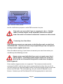
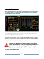
HitecFocus
User Manual
http://www.hitecastro.co.uk
[email protected]
Check us out on Facebook
http://www.facebook.com/hitecastro
Congratulations on your purchase of the ‘Hitecastro’ HitecFocus Stepper
Controller. We hope your device will provide for many years of happy focusing.
HitecFocus is a high quality digital interface between your stepper motor based
focuser and your PC or laptop.
Warranty
Hitecastro warrants that this product will be free from defects for a period of 12
months following purchase. This warranty is in addition to any statutory rights
which may exist in your jurisdiction. This warranty only applies to use as
described in this document and also for use as a telescope focus controller. No
other use is recommended or supported by Hitecastro. Any user repair or
modification attempt other than described in the troubleshooting section of this
document or directed by Hitecastro will invalidate your warranty. Hitecastro and
its affiliates disclaim any responsibility for any consequential damage or injury
which may result from use of this device except as described in this document.
Should your product fail within the first year of ownership we will repair/replace
the unit at no cost to you.
Page 2
Contents
Section
Page
Connecting the Device
Connecting to your focuser.
Connecting your own motor
Installing and Using the HitecFocus Software Suite.
Installing the HitecFocus Application and ASCOM Driver.
Using the HitecFocus application
Temperature Compensation
Using the ASCOM driver
Troubleshooting
Links
4
4
5
6
6
7
11
13
16
17
Page 3
Connecting the device
The device must be powered using a 12VDC center positive supply. Please DO
NOT remove the supplied cigar plug as this contains the fuse to the device. Any
damage occurring while this fuse is not in place is NOT covered by the warranty.
Connecting the device.
Connect a high quality USB cable to the USB port on the device and connect the
other end to a free USB port on your computer. You may use any USB 2.0 port.
HitecFocus is also backwardly compatible with the USB 1.1 standard. No matter
which version of windows you use, the USB guider should be recognised as a ‘HID
device’ without any further input from you. Connect the temperature probe to
the 3.5mm socket provided. Connect the power last (after the motor has been
connected).
Be sure that the 3.5mm plug on the temperature probe is inserted
fully. Failure to do so will result in the temperature probe not
functioning properly. Never plug/unplug the temperature probe
with the unit powered on.
If required connect the manual handset to the controller. It is not essential to do
this if you do not intend to use the handset.
Connecting to your Focuser
Connect the Male end of your focuser cable to the HitecFocus unit and connect
the other end (Female) to your focuser.
If you wish to make your own cable The following diagram shows the correct
pinout. Pins 1 to 5 should be connected as straight through. i.e pin 5 to pin 5.
The following diagram illustrates;
Page 4
Fig.1 Standard cable pinout.
Just for clarification purposes a male DB9 connector has pins.
Only make your own cable if you are competent to do so. Suitable
cables to custom lengths can be supplied by Hitecastro on special
order. Be careful to insulate all connections to ensure no short circuits
occur.
Connecting Your Own Motor
If you choose to connect your own motor to the HitecFocus unit, you do this at
YOUR OWN RISK. Hitecastro will not accept responsibility for any consequence
of using a motor supplied by the user.
Given the above warning, if you choose to connect your own focus motor you
should keep the following in mind.
Stepper motors used with HitecFocus must not require more than 1
amp per phase. Typical high quality stepper motors are .6 amp per
phase we do not recommend using motors rated above .8 amps per
phase in general.
Only unipolar stepper motors are supported. The common wire(s) must be
connected to PIN 5 and the four phases connected to the other four pins (1‐4).
You will need to use a geared stepper motor to provide enough torque to turn the
focuser and lift loads. The actual gearing ratio you need will depend on your
focuser. However you will find about 60:1 will be appropriate in most cases.
Page 5
We highly recommend using a commercially available focuser unit with an inbuilt
stepper motor. This will provide you with the most trouble free operation.
Installing and Using the HitecFocus Software Suite.
This will be the primary means of operating the focuser. Its installation and use
are now described. Before installing any of our software or ASCOM drivers, you
must ensure that your computer has the following installed.
• Dot Net Framework v3.5
• ASCOM Platform v6
See links at the end of this document.
Installing the HitecFocus Application and ASCOM Driver.
Download and run the installer application from the Hitecastro website.
Currently the URL for this is;
http://www.hitecastro.co.uk/support/HitecFocus/ASCOM_HitecFocusSetup.exe
http://www.hitecastro.co.uk/support/HitecFocus/HitecFocus_Setup.exe
However this may change after future updates. Always check our support site for
updates.
We recommend that you install the ASCOM driver first, even if you do
not intend to use it initially.
Run the installer package for the ASCOM driver by double clicking on it. We
recommend accepting the installer defaults. With the ASCOM driver installed,
you should now install the main HitecFocus application. The installer will create a
desktop icon which you can double‐click to run the application.
Page 6
Using the HitecFocus Application
When the application is run you should be presented with a minimised version of
the following screen. To expand to the fully featured version, click the expand
button (Labeled 11 in the screenshot)
For the purposes of explanation, the screenshot above has been divided into
logical groupings and numbered in yellow.
Once you have your power, motor, and USB cable plugged in click the ‘Connect’
(6) Button. If all is well, the text of the button will change to ‘Connected’ and the
focuser will retrieve the current settings from the unit.
The HitecFocus application is the primary means of making settings
changes on your controller. From v1.2 of the application onwards it is
not possible to use the features of the application at the same time
the ASCOM driver is connected. When the ASCOM driver is connected the main
features of the software are disabled. These will automatically re‐enable once
the ascom driver is disconnected.
Page 7
Some older ASCOM compliant software does not properly disconnect
ASCOM drivers on exit. Should this occur, the software features will
remain disabled. If this occurs you can do one of two things 1: restart
the software and re‐connect. The software will ask you if you if the
ASCOM driver is still connected. Answer ‘No’ and the software will
load normally. 2: On the expanded interface there is a button ‘Reset ASCOM’.
Once you are sure the ASCOM driver is not running press this to return the
software to full operation.
Let’s now look at the various areas of the software screen.
1– Focus Control area.
Here you can control how the focuser moves and change some settings including
how fast the focuser moves.
Push the ‘Focus In’ or ‘Focus Out’ to move your focus motor. You should see your
focus motor move in the direction which you clicked. We chose these directions
to suit a motor installed on the left hand side of a typical refractor telescope.
However if your motor is mounted in a different orientation then the directions
the motor moves may be incorrect. Click the ‘Swap Directions’ checkbox to
rectify this. Remember this setting is permanently stored until you change it
again.
Note: When operating in continuous mode, the controller will not
update the step position. This mode is purely designed to enable you to
slew your motor freely. It is not designed for focus operations.
For MUCH finer control over your focuser, choose the ‘Steps’ option. Now when
you press the focus buttons the motor will move only a fixed amount of steps.
The number of steps moved is determined by the number entered in the textbox
to the right of the ‘Steps’ radio button.
The ‘Steps’ option is a very powerful tool. Used correctly with a small
value in the steps field you can move the focus motor an extremely tiny
amount. Very useful for really fine focusing!
Page 8
Focus Speed
This slider changes the speed at which your focuser moves. 10 is the slowest and
1 is the fastest. Choose a setting which works best for you. Consider that at the
fastest speeds and with heavy loads the focuser may not stop immediately due to
inertia. In general choose the fastest speed which works for you!
Some motors will not operate at the fastest speeds. If your motor
does not move or produces excessive jitter, back off the speed until
smooth movement is achieved.
The ‘Step Size’ input box is really here for ASCOM compliance. It has no effect. If
you know the value in microns which your focuser actually moves per single step
you can enter it here. Most users do not need to worry about this.
2 – Positioning Area
The current position textbox displays the absolute position of the focuser. Note
this box is both read/write. To set a new value here, enter an integer between 1
and 65535 and press the set. This is the new absolute position. If you wish to
slew the focuser to a new position enter the new value (1 – 65525) in the ‘New
position’ textbox and press ‘Slew’. The focuser will move to this position and the
‘Current Position’ readout will update.
3 – Presets.
Here you can set up to four preset values which can be slewed to by pressing the
numbers buttons underneath that value. These could be, for example, the focus
position of your favorite eyepieces or CCD cameras.
4 – Step Mode
HitecFocus is capable of driving your focuser in both half step and full step mode.
Half step mode is generally the best choice for most users.
Page 9
5 – Temperature
The primary piece of information here is the current temperature reading from
the temp probe. You can choose between degrees C or F for display purposes
according to your preference. Note if you click the ‘Disable’ button, temperature
display is suppressed. The track button sends the focuser into Temperature
Compensation mode. Note the two track buttons on the right hand side and left
hand side are linked and perform exactly the same function. Two buttons are
provided solely for user convenience.
Do not engage Temperature Compensation mode until you have fully
read the section on temperature compensation later in the document.
It will not do anything until you have calculated the correct ‘Slope’ for
your setup.
Note that when first connected you will get some anomalous
temperature readings for the first few seconds. The correct
temperature will be displayed after the unit has gone through four
cycles of measurement/display
Before we conclude this section of the document we shall look at some
miscellaneous features
Netbook Mode
Click View‐>Netbook mode to enable this view mode. Only the barest minimum
features are displayed. Unfortunately, netbooks have a very limited screen size
and therefore the full app cannot be displayed. This is the best compromise we
could come up with for Netbook users. Click View‐>Netbook mode again to
return to full view mode.
Night Vision Mode
Click View ‐> Night vision to toggle the screen between Red on Black color scheme
and the default color scheme which helps preserve your eyes dark adaption.
Page
10
This concludes the section of this document on general usage of your HitecFocus
unit. In the next section we look at the temperature compensation features of
the unit and explain how to use this feature.
Temperature Compensation
Some users will operate in climates where the difference in temperature over the
course of an observing session can vary quite dramatically. Optics and other parts
of your telescope setup will respond to this. The result is the effective focal
length of your setup changes and the focus position shifts. The result may be out
of focus images even though the focus may well have been perfect at the
beginning of the session.
Note Focus shift may be caused by factors other than temperature. For
example SCT scopes may suffer from mirror shift when the scope points
to different parts of the sky. Temperature compensation does not
correct for these anomalies. Consider mirror locks if this is a significant
problem.
The first question to ask yourself is. Do I need to use temperature compensation?
Only you can answer this question. If the temperature gradient during typical
observing sessions is small or your equipment doesn’t change focus position
during a normal observing run then you don’t need to use this feature. For the
remainder of this discussion we will assume that during a normal observing run
you see significant focus shift during a run even with the scope pointed to the
same part of the sky throughout.
Enabling temperature compensation in theory is quite simple. In practice it is
more involved. You need to quantify how your scope setup responds to these
changes in temperature. Specifically you need to measure exactly how many
steps of your focuser need to be moved to correct for every degree of change in
temperature. This is known as the Slope parameter. We have provided
functionality in the HitecFocus app for you to make this measurement. The
process of collecting this data is admittedly tedious but it is a once off operation
(assuming you don’t dramatically change your equipment) and is a worthwhile
exercise.
Page
11
What we need to do is measure the how the focus position changes over time as
the temperature varies. Let’s assume that its early evening and the temperature
outside is 10C. The forecast says that tonight the temperature will fall sharply
after dark to a low of ‐8C. This is a perfect time to measure your slope parameter.
Begin with the telescope cooled to the current ambient temperature and well
focused. Press the ‘Sample’ button. The current position and the current
temperature are copied to the first available slot in the mapping area (10 in the
screenshot). Now wait until the temperature falls by an appreciable amount. Say
1 degree. Refocus your telescope precisely again and press the sample button
again. Another slot in the mapping area is filled. Continue to repeat this exercise
until you have a significant amount of data collected. 5 samples over 5 degrees C
would be the minimum recommended amount of data for a good slope
calculation. If you have devoted the evening to this purpose then continue to
measure until the temperature reaches the overnight low or at least until it stops
falling dramatically.
You will also note the Sample every X minutes option. If you fill in a value here, a
sample will be taken automatically at the specified period. Let’s give an example
of how you might use this feature in practice. In this example you set the timer to
sample every 15 minutes. You start on the hour so a sample is taken every 15
minutes thereafter. If you have software for autofocus, you set this to autofocus
5 minutes earlier than the sample is due to be taken. i.e. 10 past, 25 past, 20mins
to and 5 minutes to the hour. This way the data is collected automatically and
unattended.
When you have collected enough data, press the ‘Calc Slope’ button (Area 8). A
‘least squares’ fit is calculated from your data and the Slope box is populated with
the result.
Although this value is saved it is a good idea to note this value
elsewhere in case you every need to enter it again. Once you have a
good slope value which works for you. It will always work. You
bypass the measurement process and just enter the slope directly
and press the ‘Set’ button (in area 8)
Page
12
Once you have a good slope value calculated you can then just check one of the
‘Track’ boxes to enable temperature compensation mode.
When temperature compensation mode is enabled, all move commands sent to
the focuser should be rejected. Note the setting (9 in the screen shot) this allows
you to decide if this is to be the case or not. The ascom standard specifies that
this should be set to true. We have decided that for the most flexibility, we will
leave this decision in your hands. If this button is checked it also applied to usage
through the ASCOM driver.
With temperature compensation active, here’s what’s going on inside your
focuser.
Approximately every 10 seconds the temperature is measured internally and
averaged across the last four readings. Any differential between this and the last
measurement is calculated and if this difference exceeds a threshold which is
defined by a combination of factors, the focuser is commanded to move. Note
under even quite dramatic conditions, the focuser will never move more than one
or two steps at most. Therefore unless you’re very patient it is unlikely you will
actually see anything happening. You might just hear the focuser making
corrections very occasionally. This means that even if the focuser makes the
changes while an image is exposing, it will not affect the final image quality.
For best results you need to place the end of the temperature probe somewhere
it will not be affected by local and short lived changes. For example, don’t place if
where it is likely to be influenced by the observer’s body heat. A good place
might by on the outside of the telescope tube farthest from the observer.
As you can see from the above, getting good temperature compensation like
many things is a skill which you learn, like autoguiding it requires practice and
understanding to get best results. HitecFocus provides you with the tools you
need to learn what works well for you. At this point it is worth mentioning again,
if you don’t need to use temperature compensation then don’t.
Another way to get your slope value correct is trial and error. You could start with
a value of say 5 or maybe use a friend’s value who has similar equipment. You
can then adjust this value until you get it just right for you. Note that other
Page
13
people’s measurements might need the sign of the slope inverted to work for
you.
Using the ASCOM driver
VERY IMPORTANT
Before installing our ascom driver ensure that you have already installed the
latest version of the ASCOM platform from http://www.ascom‐standards.org
At the time of writing this is version 6
Also note that installing the ASCOM driver sets the controller values back to
default factory settings. If you wish to avoid this install the ASCOM driver
BEFORE the PC application.
We cannot go into specifics about the nuances of each individual piece of ASCOM
compliant software. However there are some similarities which you will find
across all software.
Whatever software you use, you should go to the ASCOM focuser chooser and
select ‘HitecFocus’
Click Properties to display the setup dialog.
Page
14
Click OK
You are reminded that all settings should be made using our supplied
PC application. You can have this open at the same time as the ASCOM
driver so that setting changes can be made ‘On the fly’.
Depending on the software you are using, you may need to click ‘Connect’ (e.g.
Maxim DL). However some software applications will just connect automatically.
For use of the focuser and general focus operations within your third party
software, consult the documentation supplied with that software.
Page
15
Troubleshooting
Q: I cannot install the software application or ASCOM driver.
A: Ensure that you have dot net framework v3.5 and ASCOM platform v6 (at least)
installed.
Q: My HitecFocus unit does not connect to my computer
A: Ensure that your version of windows has all the latest updates and service
packs. Please note any error message you are given and contact support
([email protected])
Q: My device connects but does not move my focus motor or my focus vibrates
too much.
Ensure that the focus speed is not set too high. Try speed 5 as a general start and
adjust from here to suit. Check all cables are seated correctly and intact.
Q: I cannot autofocus with my focus motor.
A: We cannot support third party software issues. We recommend that you join
some of the many yahoo groups dedicated to these packages. There you will find
many helpful astronomers including some of the Hitecastro staff who will be
more than happy to help you with your autoguiding queries.
If the above does not solve your problem first check our support area on our
website http://www.hitecastro.co.uk We will add knowledge base articles as
they arise. We also have a yahoo support group which we recommend you join.
http://tech.groups.yahoo.com/group/hitecastro/
Failing that please contact us by e‐mailing
[email protected]
or by contacting your retailer.
Page
16
Links
Requirements for using our software
Dot Net Platform Version 3.5
http://www.microsoft.com/downloads/
ASCOM Platform
http://www.ascom‐standards.org/
Some Software which leverages the ASCOM standard for focusers
CCD Auto Pilot
http://www.ccdware.com/
Maxim DL
http://www.cyanogen.com/
CCD Soft
http://www.bisque.com/sc/shops/store/CCDSoftWin2.aspx
Sharp Cap (Free)
http://sites.google.com/site/rwgastro/sharpcap
EQMOD (Free)
http://eq‐mod.sourceforge.net/
FocusMax (Free)
http://users.bsdwebsolutions.com/~larryweber/FocusMaxDownload.htm
Please note that there are many more applications available. Hitecastro has no
connection with any of the above software suppliers. Users should evaluate any
software first to ensure that it meets your needs
Page
17