1
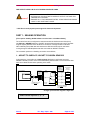
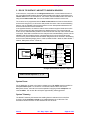
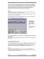
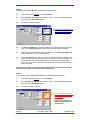
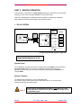
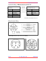
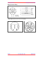
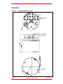
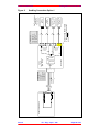
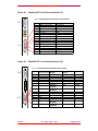
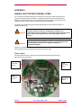
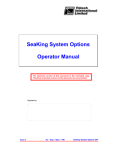
SeaKing Subsea Junction Box Operator & Installation Manual The electronic version of this document is the controlled copy. Therefore all printed versions of this document are uncontrolled. Supplied by: Issue 4 TIL – Eng – Spec – 026 SeaKing Subsea Junction Box OIM COPYRIGHT © Tritech International Ltd The copyright in this document is the property of Tritech International Limited. The document is supplied by Tritech International Limited on the understanding that it may not be copied, used, or disclosed to others except as authorised in writing by Tritech International Limited. Tritech International Limited reserved the right to change, modify and update designs and specifications as part of their ongoing product development programme. F063.1 Tritech International Ltd SeaKing Subsea Junction Box OIM Handling of Electrostatic-Sensitive Devices .........................................................................................5 Safety Statements ...................................................................................................................................7 Technical Support ..................................................................................................................................7 INTRODUCTION ..................................................................................................................................8 KEY FEATURES:................................................................................................................................8 Functionality ....................................................................................................................................8 Telemetry Options ............................................................................................................................9 Power Distribution ...........................................................................................................................9 System Compatibility ........................................................................................................................9 Configuration ...................................................................................................................................9 OPERATIONAL OVERVIEW...........................................................................................................10 SWITCH OPTIONS.................................................................................................................................11 PART 1: SEAKING OPERATION ...................................................................................................12 1. ARCNET TO SURFACE / ARCNET TO SUBSEA SENSORS ............................................................12 System Power .................................................................................................................................13 System Telemetry ............................................................................................................................13 Junction Box Wiring - SeaKing ARCNET In & ARCNET Out .......................................................14 Mating Connector Wiring...............................................................................................................14 2. RS-232 TO SURFACE / ARCNET TO SUBSEA SENSORS ................................................................15 System Power .................................................................................................................................15 System Telemetry ............................................................................................................................15 Junction Box Wiring - SeaKing RS232 In & ARCNET Out...........................................................16 Mating Connector Wiring...............................................................................................................16 Checking Connection in the SETUP program................................................................................17 Changing RS-232 Baud Rate..........................................................................................................18 Establishing RS-232 link using (Recovery) 9600 Baud Speed .......................................................20 PART 2: WINSON OPERATION .....................................................................................................23 1. RS-232 SYSTEM ..........................................................................................................................23 System Power .................................................................................................................................23 System Telemetry ............................................................................................................................23 Junction Box Wiring – Winson RS232 IN & RS232 OUT ..............................................................24 Mating Connector Wiring...............................................................................................................24 2. RS-485 SYSTEM ..........................................................................................................................25 System Power .................................................................................................................................25 System Telemetry ............................................................................................................................25 Junction Box Wiring – Winson RS485 IN & RS485 OUT ..............................................................25 Mating Connector Wiring...............................................................................................................26 APPENDIX 1. .......................................................................................................................................27 Figure 1: Figure 2: Figure 3: Figure 4: Figure 5: Figure 6a: Figure 6b: Junction Box Dimensions .......................................................................................27 SeaKing Connection Option 1 ................................................................................28 SeaKing Connection Option 2 ................................................................................29 WINSON Connection Option 1...............................................................................30 WINSON Connection Option 2...............................................................................31 SeaKing AIF Card Communications Port ..............................................................32 WINSON AIF Card Communications Port.............................................................32 APPENDIX 2. .......................................................................................................................................33 SUBSEA JUNCTION BOX INTERNAL FUSES. ............................................................................33 Fuse Location .................................................................................................................................33 Issue 4 TIL – Eng – Spec – 026 Page 4 of 34 Tritech International Ltd SeaKing Subsea Junction Box OIM Handling of Electrostatic-Sensitive Devices Attention Observe Precautions for handling Electrostatic Devices Caution Handling of Electrostatic-Sensitive Devices Certain semiconductor devices used in the equipment are liable to damage due to static voltages. Observe the following precautions when handling these devices in their unterminated state, or sub-units containing these devices: • Persons removing sub-units from any equipment using electrostatic sensitive devices must be earthed by a wrist strap via a 1MΩ resistor to a suitable discharge reference point within the equipment. • Soldering irons used during any repairs must be low voltage types with earthed tips and isolated from the Mains voltage by a double insulated transformer. Care should be taken soldering any point that may have a charge stored. • Outer clothing worn must be unable to generate static charges. • Printed Circuit Boards (PCBs) fitted with electrostatic sensitive devices must be stored and transported in appropriate anti-static bags/containers. F110.0 Issue 4 TIL – Eng – Spec – 026 Page 5 of 34 Tritech International Ltd SeaKing Subsea Junction Box OIM Warranty Statement Tritech International Limited herein after referred to as TIL TIL warrants that at the time of shipment all products shall be free from defects in material and workmanship and suitable for the purpose specified in the product literature. The unit/system warranty commences immediately from the date of customer acceptance and runs for a period of 365 days. Customer acceptance will always be deemed to have occurred within 72 hours of delivery. Note: Any customer acceptance testing (if applicable) must be performed at either TIL premises or at one of their approved distributors unless mutually agreed in writing prior to despatch. Conditions: These include, but are not limited to, the following: 1 The warranty is only deemed to be valid if the equipment was sold through TIL or one of its approved distributors. 2 The equipment must have been installed and commissioned in strict accordance with approved technical standards and specifications and for the purpose that the system was designed. 3 The warranty is not transferable, except or as applies to Purchaser first then to client. 4 TIL must be notified immediately (in writing) of any suspected defect and if advised by TIL, the equipment subject to the defect shall be returned by the customer to TIL, via a suitable mode of transportation and shall be freight paid. 5 The warranty does not apply to defects that have been caused by failure to follow the recommended installation or maintenance procedures. Or defects resulting from normal wear & tear, incorrect operation, fire, water ingress, lightning damage or fluctuations in vehicles supply voltages, or from any other circumstances that may arise after delivery that is outwith the control of TIL. (Note: The warranty does not apply in the event where a defect has been caused by isolation incompatibilities.) 6 The warranty does not cover the transportation of personnel and per diem allowances relating to any repair or replacement. 7 The warranty does not cover any direct, indirect, punitive, special consequential damages or any damages whatsoever arising out of or connected with misuse of this product. 8 Any equipment or parts returned under warranty provisions will be returned to the customer freight prepaid by TIL 9 The warranty shall become invalid if the customer attempts to repair or modify the equipment without appropriate written authority being first received from TIL. 10 TIL retains the sole right to accept or reject any warranty claim. 11 Each product is carefully examined and checked before it is shipped. It should therefore be visually and operationally checked as soon as it is received. If it is damaged in anyway, a claim should be filed with the courier and TIL notified of the damage. Note: TIL reserve the right to change specifications at any time without notice and without any obligation to incorporate new features in instruments previously sold. Note: If the instrument is not covered by warranty, or if it is determined that the fault is caused by misuse, repair will be billed to the customer, and an estimate submitted for customer approval before the commencement of repairs. F167.1 Issue 4 TIL – Eng – Spec – 026 Page 6 of 34 Tritech International Ltd SeaKing Subsea Junction Box OIM Safety Statements Caution Throughout the manual certain safety or operational related comments and requirements will be highlighted to the operator by indications identified by the adjacent symbol and text. ! Technical Support Contact your local agent or Tritech International Ltd Mail Tritech International Ltd. Peregrine Road, Westhill Business Park, Westhill, Aberdeen, AB32 6JL, UK Telephone ++44 (0)1224 744111 Fax ++44 (0)1224 741771 Email [email protected] Web www.tritech.co.uk An out-of-hours emergency number is available by calling the above telephone number If you have cause to use our Technical Support service, please ensure that you have the following details at hand prior to calling: • • • System Serial Number ( if applicable ) Fault Description Any remedial action implemented Due to the expansion of equipment capabilities and the fact that new sub-modules are continually being introduced, this manual cannot detail every aspect of the operation. Issue 4 TIL – Eng – Spec – 026 Page 7 of 34 Tritech International Ltd SeaKing Subsea Junction Box OIM INTRODUCTION The Tritech Subsea Junction Box provides the connection interface to the Tritech range of networked survey suites. The Junction box provides the main telemetry link to the surface and acts as the splitter for connecting several networked sensors together to be controlled from this single telemetry link to the surface. At the surface, the Tritech Surface Control Unit (SCU) provides the user interface for controlling and displaying the array of sensors connected together on the ROV / deployment vessel. This range of networked sensors includes Imaging Sonars, Profilers and Bathymetry & Oceanographic packages. Tritech have 2 different survey packages and the Junction Box can be connected in each of these. These 2 survey packages are; 1) SEAKING 2) WINSON. The SEAKING and WINSON survey packages include a similar range of sensors which are not directly inter-connectable. The SEAKING range is the more recent package and offers the benefits of more recent technology. Amongst these, a long-line, high-speed telemetry interface (ARCNET) is used which provides the capacity for transferring larger streams of sensor data that is prevalent from the increase in sample data that is a result of the higher resolution of these sensors. The Junction box's telemetry link to the surface can be configured to either (2-wire) ARCNET or (3-wire) RS-232 #. # The J-box can be configured to communicate to the surface using RS-232 or ARCNET, whilst communicating to each of the connected Sensor heads over the ARCNET LAN. The WINSON survey suite is the earlier range of Sonars, Profilers and Bathymetry packages. The telemetry that this system uses is (3-wire) RS-232 or (2-wire) RS-485 at 9600 Baud. For WINSON connection, the J-box does not require to be powered itself but distributes power and telemetry on the inlet port to each of the Sensor connection ports. Further on in this manual, more details can be found for interfacing the Junction Box into both survey packages; i) For operation of the Junction Box as part of a SEAKING survey system, refer to Part 1 of this manual. ii) For operation of the Junction Box as part of a WINSON survey system, refer to Part 2 of this manual. KEY FEATURES: Functionality The J-box is pressure rated to a maximum depth of 4000 metres and can be installed in any suitable location on the ROV. It provides the subsea split to the SeaKing / WINSON sensor suites, with connection for up to a maximum of 4 sensors comprising Sonars, Profilers and Bathy. Issue 4 TIL – Eng – Spec – 026 Page 8 of 34 Tritech International Ltd SeaKing Subsea Junction Box OIM Telemetry Options The J-box communicates with the surface control card (AIF card) over 2-wire ArcNet / RS485 or 3-wire RS-232 telemetry link. ARCNET communications require termination resistors to be installed surface and subsea. The subsea termination resistor is installed in a (yellow) colour coded connector on the J-box. Caution ! This should be removed for RS-232 or RS-485 connections used by WINSON Sensor Heads. Power Distribution The J-box is powered from a DC supply of range +21 to +30VDC. This DC supply is then distributed to the WINSON / SEAKING Sensor heads via each head’s connection port on the J-box. Caution ! Sensor heads will require 24VDC and a 4-head sensor suite would require approx. 2A at this voltage level. Fuse Protection Each of the head connection ports have an internal fuse on the 24 V power rail. These fuses are rated to 3Amps and are included to help protect the head and J box in the event of water ingress to cable or connectors. Details can be found System Compatibility The J-box can be used to connect together sensors from either the WINSON or SEAKING survey suites. Sensors from these two systems however cannot be mixed as they require different, dedicated Surface Control Units (SCUs). • WINSON operates over RS-232 or RS-485 networked communications at 9600 baud. • SEAKING however uses an ARCNET networked communications at 156.2 or 78.1 kbaud. At the 156.2 kbaud rate, the ARCNET will drive over unshielded twisted pair cabling up to 1.5 kilometres in length. Lowering the telemetry rate to 78.1 kbaud will extend this line drive to approximately 2.5 kilometres. Configuration All telemetry and power options on the J-box are configurable via a pressure rated dial switch on the outside face of the J-box. Later models will have a Blue cap fitted over the switch to allow improved immunity to water ingress, see below for detail on how to access andset the switch. Caution Issue 4 ! J-box power supply must be removed before dial switch adjustment. TIL – Eng – Spec – 026 Page 9 of 34 Tritech International Ltd SeaKing Subsea Junction Box OIM OPERATIONAL OVERVIEW The Junction box can be installed at any convenient location on the ROV, preferably central to the SeaKing heads that will be connected. There are 4 mounting holes (M8 x 1.25-6H) located on the base of the box (see Appendix) to assist with installation. The unit should be provided with adequate lengths of interconnect cables in order to connect the SeaKing heads. These interconnect cables (Part No. S1086) are available from Tritech in lengths of 1, 2 and 4 metres, with other lengths available on request. The junction box provides the power and telemetry interface for up to 4 x SeaKing heads. Caution ! Alternatively the box can be used as the connection interface for earlier Tritech survey suites including the WINSON SCU-3 system - details of which are contained near the back of this manual. Junction Box Connection Ports Surface telemetry to and from the Surface Control Unit (SCU) is connected through the central 8-pin Burton connector (Input 'Surface' Port). This telemetry can be either asynchronous RS-232 or ARCNET LAN. The telemetry settings are selectable via an external dial on the façade of the unit, see 'Switch Options' below. The 8-pin Burton connector also doubles as the input port for system power. The Junction box requires to be powered from a 21-30VDC local PSU. This power input is then distributed to all four of the 6-pin Tritech head interface ports (Output 'Head' Ports A, B, C, D). Output Ports A, B, C & D have 5 active pins; i) 2 x pins for providing DC power supply for SeaKing heads. ii) 2 x pins for ARCNET telemetry. iii) 1 x pin used for Profiler Handshaking link. N.B. Full Wiring details can be found in later sections. Issue 4 TIL – Eng – Spec – 026 Page 10 of 34 Tritech International Ltd SeaKing Subsea Junction Box OIM SWITCH OPTIONS The Rotary dial switch on earlier models was exposed and can easily be set. Newer models have a blue pressure cap over this switch. To access the switch, remove the 4ea M4 socket cap bolts which fit the cap to the J-Box lid. The cap can be lifted off and access to the dial obtained. The switch should be adjusted with the key provided or if this is not available then a suitable 1.2 X 6.5mm flat blade screwdriver can be carefully used, see below. Blue cap fitted over Rotary mode select switch Switch adjusted using supplied key On models factory fitted with the blue cap, always ensure that the O-ring and blue cap are refitted prior to immersion. Ensure O-ring is clean and re-fitted around the rotary switch prior to refitting the blue cap. Arrow head indicates mode selected. The external rotary dial located on the face of the Junction Box provides 8 operational modes... Switch Option 1 2 3 4 5 6 7 8 Issue 4 Input ‘Surface’ 21-30VDC SeaKing RS-232 SeaKing RS-232 SeaKing RS-232 SeaKing RS-232 ARC-NET ARC-NET ARC-NET ARC-NET Output ‘A-D’ 21-30VDC Local ARC-NET Local ARC-NET Local ARC-NET Local ARC-NET ARC-NET ARC-NET ARC-NET ARC-NET TIL – Eng – Spec – 026 AUX Port ** 232/485 RS-232 RS-485 RS-232 RS-485 N/A N/A N/A N/A Power O/P 21-30VDC 21-30VDC 12VDC 12VDC 21-30VDC 21-30VDC 12VDC 12VDC Page 11 of 34 Tritech International Ltd SeaKing Subsea Junction Box OIM USE OUTPUT PORTS A-B OR C-D FOR DUAL PROFILER PAIRS Caution ! • ENSURE POWER ISOLATED BEFORE CHANGING OPTION SWITCH. • OPTIONS 5-8, AUX PORT NOT IN USE BUT OUTPUT VOLTAGE STILL PRESENT ON THIS PORT. • ENSURE TO FIT THE PRESSURE RATED, O-RING SEALED BLANKING CAPS TO ANY PORTS NOT IN USE. ** AUX Port is multi-purpose port assigned for future developments PART 1: SEAKING OPERATION [This requires SeaKing SONV3 software version 1.50-> or SeaNet software] The Junction Box can be configured to communicate with the Surface Control Unit (SCU) over RS-232 or ARCNET telemetry. ARCNET should be the preferred option as this provides a higher capacity data link which will allow for connection of a larger number of Sensors without affecting the update rates of these Sensors. RS-232 should only be used when running through a Data Multiplexer that does not include an ARCNET interface. The connection options for a SeaKing connection are as follows; 1. ARCNET TO SURFACE / ARCNET TO SUBSEA SENSORS In this mode, the Junction Box is a dumb terminal distributing Local Power Input and ARCNET Telemetry to each of the connected SeaKing Sensor heads. The Junction Box does NOT have a Node Number when operating in this mode. Tritech 6-Pin Pin1: ARCNET-A Pin2: ARCNET-B Pin3: 24VDC (o/p) Pin4: Gnd (o/p) Pin5: Profiler Handshake SAV4 Junction Box (P/N 3107) 5 4 D Pin1: ARCNET-A Pin2: ARCNET-B Pin3: 24VDC Pin4: Gnd (Profiler Handshake) BURTON 1508 Surface Control Unit J2.1 5 C 4 Any Combination of Sensors. For example... Sonar Node 2 Bathy Node 40 4 Local PSU 5 (Profiler Handshake) B 4 4 5 A No Node Number Install 270 ohm surface termination resistor Master Profiler Node 20 Slave Profiler Node 21 Install Yellow Waterblock (~ has 39 ohm termination resistor fitted) # Larger representation diagram in Appendix. Select Switch Options 5, 6, 7, 8 Issue 4 TIL – Eng – Spec – 026 Page 12 of 34 Tritech International Ltd SeaKing Subsea Junction Box OIM System Power For the distribution of power to the heads, a voltage input of 21- 30VDC must be supplied on the Input 'Surface' port. For connection of a full suite of Dual Profilers, Sonar and Bathymetric Sensor, the local PSU must be capable of supplying at least 2 Amperes at a nominal 24VDC. System Telemetry The ARCNET telemetry link requires termination resistors to be installed at either end of the cable in the same way as a standard ARCNET system; - - The surface 270 ohm resistor can be located within the 15-way 'd' connector shell. This is the connector that mates at the rear end of the SCU. This resistor should be fitted between pins 8 and 15 on this connector. The subsea 39 ohm resistor is fitted in the Yellow Waterblock adapter that is supplied with the Junction box. For SeaKing operation, this adapter MUST be installed at all times and fitted to any of the Output Head ports (A,B,C or D). Issue 4 TIL – Eng – Spec – 026 Page 13 of 34 Tritech International Ltd SeaKing Subsea Junction Box OIM Junction Box Wiring - SeaKing ARCNET In & ARCNET Out Burton 1508 Bulkhead Connector (Input Port I) Pin 1 Pin 2 Pin 3 Pin 4 Pin 5 Pin 6 Pin 7 Pin 8 Tritech 6 Way Bulkhead Connector (Output Ports A, B, C, D) Internal Box Fixed Links Pin 1 Pin 2 Pin 3 Pin 4 Pin 5 Pin 6 ARCNET LAN-A ARCNET LAN-B 24VDC Input 0VDC Input N/A Chassis Ground N/A N/A # ARCNET LAN-A ARCNET LAN-B 24VDC Output 0VDC Output Profiler Sync. # Case Internal Box Links between A-B and C-D. Mating Connector Wiring 1 1 6 2 2 4 5 4 Connector Face View Yellow ArcNet LAN-B Blue +24 VDC 3 3 5 ArcNet LAN-A Red 0 VDC Black Profiler Sync. Green Screen 6 Tritech 6 Way Underwater Cable Connector (Ports A,B,C,D) 7 Aux LAN-A LAN-B 1 2 3 0VDC N/A Chassis Gnd 4 5 8 4 2 5 24VDC 1 3 I D A 6 N/A N/A 7 8 C Burton 5501 U/W Cable Connector (Port I ) Issue 4 6 B Face View of Junction Box TIL – Eng – Spec – 026 Page 14 of 34 Tritech International Ltd SeaKing Subsea Junction Box OIM 2. RS-232 TO SURFACE / ARCNET TO SUBSEA SENSORS In this mode, the Junction Box is an intelligent terminal which communicates with each of the connected ARCNET SeaKing Sensors whilst translating this data for transmission to the surface node via the 3-wire RS-232 link. The surface node is the AIF interface card which is assigned the Node number 255. This card is installed inside the SCU Processor unit. The Junction box is programmed with the Node number 254 and will communicate with the surface node using this I.D. It will receive data packets from each of the connected SeaKing Sensors over the ARCNET LAN and attach these in its own data packets addressed to the surface node and sent over the RS-232 link. In the opposite direction, the surface node will communicate through the Node 254 Junction Box in order to send any data commands to the SeaKing Sensors. The Junction Box will receive its own addressed data packets from the surface node and strip of the contained data commands. These data commands are then relayed to the intended SeaKing Sensor over the ARCNET LAN. Each SeaKing Sensor is programmed with it's own unique Node number which is factory set and follows the Node number assignments which are fixed in the SeaKing surface control software [Imaging Sonar = Node 2, Master Profiler = Node 20, Slave Profiler = Node 21, Bathymetric Sensor = Node 40]. Tritech 6-Pin Pin1: Pin2: Pin3: Pin4: Pin5: ARCNET-A ARCNET-B 24VDC (o/p) Gnd (o/p) Profiler Handshake Any Combination of Sensors. For example... BURTON 1508 SAV4 Junction Box (P/N 3107) 5 5 B 4 (Profiler Handshake) RS-232 J2.1 ArcNet Local PSU Sonar Node 2 D 4 CPU 5 5 4 C Pin3: 24VDC Pin4: Gnd Pin5: RS-232 Gnd Pin7: RS-232 Tx Pin8: RS-232 Rx (Profiler Handshake) Surface Control Unit 5 A 4 Bathy Node 40 Master Profiler Node 20 Slave Profiler Node 21 Node 254 Install Yellow Waterblock (~ has 39 ohm termination resistor fitted) # Larger representation diagram in Appendix. Select Switch Options 1, 2, 3, 4 System Power For the distribution of power to the heads a voltage input of 21- 30VDC must be supplied on the Input 'Surface' port. For connection of a full suite of Dual Profilers, Sonar and Bathymetric Sensor, the local PSU must be capable of supplying at least 2 Amperes at a nominal 24VDC. The Junction Box will require approximately 150mA @ 24VDC. System Telemetry The ARCNET telemetry link between the SeaKing Sensor heads and the Junction Box requires a single termination resistor to be installed between the 2 LAN wires. This termination resistor should be of value between 39 and 100 ohms. Issue 4 TIL – Eng – Spec – 026 Page 15 of 34 Tritech International Ltd SeaKing Subsea Junction Box OIM N.B. For this purpose, a 39 ohm termination resistor is fitted in the Yellow Waterblock adapter that is supplied with the Junction box. For SeaKing operation, this adapter MUST be installed at all times and fitted to any of the Output Head ports (A,B,C or D). Maintain the factory default ARCNET Baud rate of 156.2kBaud. There is no need to lower this rate as only short interconnect cables will be installed between the Junction Box and the connected SeaKing Sensor heads. The RS-232 telemetry link to the surface can be adjusted to suit the Modem / Multiplexer that will be used on the system. It is recommended that the factory default setting of 115.2kBaud be used whenever possible as this will provide enough bandwidth to run multiple SeaKing Sensors at optimum speeds and resolutions. Details on changing the RS-232 Baud rate can be found in the next few pages. Junction Box Wiring - SeaKing RS232 In & ARCNET Out Burton 1508 Bulkhead Connector (Input Port I) Pin 1 Pin 2 Pin 3 Pin 4 Pin 5 Pin 6 Pin 7 Pin 8 Tritech 6 Way Bulkhead Connector (Output Ports A, B, C, D) Internal Box Fixed Links N/A N/A 24VDC Input 0VDC Input RS-232 Ground Chassis Ground RS-232 Tx RS-232 Rx Pin 1 Pin 2 Pin 3 Pin 4 Pin 5 Pin 6 # ARCNET LAN-A ARCNET LAN-B 24VDC Output 0VDC Output # Profiler Sync. Case Internal Box Links between A-B and C-D. Mating Connector Wiring 1 1 6 2 2 ArcNet LAN-B +24 VDC 3 3 5 ArcNet LAN-A 4 5 4 Connector Face View 0 VDC Profiler Sync. 6 Yellow Blue Red Black Green Screen Tritech 6 Way Underwater Cable Connector (Ports A,B,C,D) Issue 4 TIL – Eng – Spec – 026 Page 16 of 34 Tritech International Ltd SeaKing Subsea Junction Box OIM 7 6 Aux N/A N/A 1 2 3 RS-232 Gnd Chassis Gnd 0VDC 1 24VDC 5 4 8 5 4 2 3 I D A 6 RS-232 Tx RS-232 Rx 7 8 C Burton 5501 U/W Cable Connector (Port I ) B Face View of Junction Box Checking Connection in the SETUP program STEP 1: After the above wiring has been followed and Junction box RS-232 telemetry to the surface is connected to the SeaKing SCU Processor, apply power to the J-box. STEP 2: Check the RS-232 telemetry connection between the SeaKing surface control unit (SCU) and the Junction box. On the SeaKing/SeaNet SCU, run the SETUP* utility program and check that the following Node table entries appear; * Depending on what software program is installed (SeaNet or SONV3) there are 2 versions of the Setup program; ‘V3Setup’, ‘SeaNet Setup’ (Never run SONV3 and V3SETUP programs at the same time). Examples for V3Setup will be given with associated SeaNet Setup actions in brackets. ‘SeaNet Setup’ ‘V3Setup’ Node 255 is the surface AIF interface card. (This node should always appear in the table) Node 254 is the Junction box under RS-232 surface telemetry control. If Node 254 does not appear, first check connections and power, then refer to the 'Changing RS-232 Baud Rate' and 'Establishing RS-232 link using (Recovery) 9600 Baud Speed' sections further on. Issue 4 TIL – Eng – Spec – 026 Page 17 of 34 Tritech International Ltd SeaKing Subsea Junction Box OIM All Nodes in the table should appear with Program column status displaying "Upto Date" (“OK” in SeaNet Setup). If "Needs Update" (“Update” in SeaNet Setup) is instead displayed, highlight the row of this Node (as shown with Node 254 in V3SETUP table above) and press the activated 'Program' button on the bottom-centre of display (or click on ‘Action’ -> ‘Program’ in SeaNet Setup). Wait until "Prog Done OK" status appears and then press 'Rebuild' button, confirming Program status now changed to "Upto Date". STEP 3: With Junction box detected in the SETUP table, now connect any SeaKing Sensor head to any of the Head Ports (A, B, C, D) of the Junction box. Ensure that the Yellow Waterblock adapter, which includes the ARCNET termination resistor, is installed on any one of the Head Ports. The SETUP table should immediately display the Node number of the connected SeaKing Sensor (V3SETUP table shown in example below); • For example an Imaging Sonar will appear as Node 2 when connected through the Junction Box. (Ensure 'Program' status is "Upto Date" or “OK” refer to Step 2) Any connected SeaKing Sensor heads must be set to ARCNET with the Full Baud Rate of 156.2kBaud. (Refer to 'System' section of SeaKing Operator's manual for more details on configuring Baud Rate switches) Changing RS-232 Baud Rate On the SeaKing/SeaNet surface control unit (SCU), the SETUP utility program can be used to change the RS-232 telemetry speed between the SCU and the Junction Box. This will normally be left at the factory setting of 115.2kBaud, however there may be cases that this speed has to be lowered to accommodate system Modems and Multiplexers. STEP 1: First establish that the Junction Box appears in the SETUP table as Node 254 and it's 'Program' status displays "Upto Date" (“OK” in SeaNet Setup) - Refer to the previous section 'Checking Connection in the SETUP program,'. Issue 4 TIL – Eng – Spec – 026 Page 18 of 34 Tritech International Ltd SeaKing Subsea Junction Box OIM STEP 2: Configuring the Junction Box with the desired RS-232 Baud rate. i) In the SETUP table, highlight the row of Node 254. ii) Press 'Program User Data' button (click on ‘Action’ – ‘Setup’ in SeaNet Setup) and then click on the 'Baud Rates' button. iii) The following panel will appear… These are the settings for the RS-232 telemetry link to the surface control unit (SCU). iv) The Async 0 (LAN) panel includes the settings for the RS-232 telemetry link to the SCU. It is the Right channel that needs to be set with the desired link speed. v) After changes have been made, press the 'Exit' button and ReProgram Node 254 when prompted (or just ‘OK’ in SeaNet Setup). vi) Press the 'Rebuild' button. Only the surface AIF card (Node 255) will appear in the list and this will confirm that telemetry with the Node 254 Junction box has been lost. The AIF will still try to communicate with the Junction box and will display TMO errors, do not worry as this is because both Nodes are operating at different baud rates at this stage. Now proceed with Step 3 and set the AIF card (Node 255) telemetry to the same baud rate that has just been set for the Node 254 Junction box. STEP 3: Configuring the surface AIF interface card with the desired RS-232 Baud rate. i) In the SETUP table, highlight the row of Node 255. ii) Press 'Program User Data' button (click on ‘Action’ – ‘Setup’ in SeaNet Setup) and then click on the 'Baud Rates' button. iii) The following panel will appear… These are the settings for the RS-232 telemetry link to the Junction Box. Ensure 'Lan' and 'Async 1 (AUX)' settings appears as indicated left. Issue 4 TIL – Eng – Spec – 026 Page 19 of 34 Tritech International Ltd SeaKing Subsea Junction Box OIM iv) The Async 0 (LAN) panel includes the settings for the RS-232 telemetry link to the SCU. It is the Right channel that needs to be set with the desired link speed. v) After changes have been made, press the 'Exit' button and ReProgram Node 255 when prompted (or just ‘OK’ in SeaNet Setup). vi) If the SETUP Node list does not update after 10 seconds, press the 'Rebuild' button. Node 254 should re-appear confirming that the surface AIF card (Node 255) is communicating with the Node 254 Junction box over the new telemetry baud rate. Establishing RS-232 link using (Recovery) 9600 Baud Speed N.B. This requires a switch change to be made inside the Junction Box. This recovery should only be attempted as a last resort measure. STEP 1: Remove the lid of the Junction box using the special spanner provided with the unit. N.B. The lid has no internal hardware connections that will break whilst unscrewing off the lid. STEP 2: There are 2 circular PCBs fixed to the lid. The smaller of these is the CPUCV3 PCB. This is this board that contains the Baud Speed switch ('SW1' Switch 1). i) Set 'SW1' Switch 1 to the On position to set the Junction Box with the Recovery 9600 Baud Speed. 'SW1' Switch 1 is used to select between the 2 pre-set communication rates for ARCNET and RS-232. Since the Junction Box operates ARCNET and RS-232 simultaneously, 'SW1' Switch 2 will change both these telemetry speeds at the same time. Issue 4 TIL – Eng – Spec – 026 Page 20 of 34 Tritech International Ltd SeaKing Subsea Junction Box OIM CPUCV3 'SW1' The switch settings are as follows… ON 1 Switch 1 (RS-232) Switch 1 (ArcNet) Switch 2 2 Off = 115,200 On = 9,600 Off = 156,200 On = 78,100 On = Normal * Off = Boot * Switch 2 = On is factory setting, do not touch. SW2 in Recovery 9600 Baud Position Switch 1 = Off is the Normal Operating setting. N.B. This relates to the Async 0 (LAN) Right channel described in the 'Changing RS-232 Baud Rate' section. Switch 1 = On is the Recovery 9600 Baud Speed position. N.B. This relates to the Async 0 (LAN) Left channel described in the 'Changing RS-232 Baud Rate' section. ii) Leave the Junction Box lid for now. Do not re-screw the lid back into the main housing as the switch will need to be reset after recovery of communications. STEP 3: Configure the surface AIF interface card to the 9600 Baud rate. i) In the SETUP table, highlight the row of Node 255. ii) Press 'Program User Data' button (click on ‘Action’ – ‘Setup’ in SeaNet Setup) and then click on the 'Baud Rates' button. iii) The following panel will appear… These are the settings for the RS-232 telemetry link to the Junction Box. Ensure 'Lan' and 'Async 1 (AUX)' settings appears as indicated left. iv) The Async 0 (LAN) panel includes the settings for the RS-232 telemetry link to the SCU. It is the Right channel that needs to be set with the 9600 Baud speed. v) After changes have been made, press the 'Exit' button and ReProgram Node 255 when prompted (or just ‘OK’ in SeaNet Setup). STEP 4: Re-connect the RS-232 telemetry between the surface control unit (SCU) and the Junction box and apply power to the box. Issue 4 TIL – Eng – Spec – 026 Page 21 of 34 Tritech International Ltd SeaKing Subsea Junction Box OIM STEP 5: In the SETUP Node list, the Node 254 Junction should now appear, press the 'Rebuild' button if this is not the case. The appearance of Node 254 in the list will confirm that the surface AIF card (Node 255) is communicating with the Node 254 Junction box using the 9600 Baud rate. STEP 6: Refer to the 'Changing RS-232 Baud Rate' Section and follow Step 2 (Parts i -> v) in order to set the RS-232 telemetry rate. (Remember that the Junction box is still operating over the Recovery 9600 Baud rate at the moment) STEP 7: Set 'SW1' Switch 1 back to the Off position to set the Junction Box back with the Normal Operating Baud Speed that has just been set in Step 6 above. STEP 8: Refer to the 'Changing RS-232 Baud Rate' Section and follow Step 3 (Parts i -> vi) in order to set the RS-232 telemetry rate for the Node 255 AIF card. This will match the Baud rate that was set in Step 6 above. Issue 4 TIL – Eng – Spec – 026 Page 22 of 34 Tritech International Ltd SeaKing Subsea Junction Box OIM PART 2: WINSON OPERATION In this mode, the Junction Box is a dumb terminal distributing Local Power Input and surface Telemetry to each of the connected WINSON 'ST'/'SD' Sensor heads. Refer to the WINSON SCU-3 Operators manual for details on configuring the WINSON system between the RS-232 and RS-485 communications options. 1. RS-232 SYSTEM Tritech 6-Pin Pin1: RS-232 Tx Pin2: RS-232 Rx Pin3: 24VDC (o/p) Pin4: 0VDC (o/p) / RS-232 Gnd SAV4 Junction Box (P/N 3107) J2.1 D 4 C 4 WINSON AIF Card 4 4 (Profiler Handshake) BURTON 1508 Pin1: RS-232 Tx Pin2: RS-232 Rx Pin3: 24VDC Pin4: 0VDC / RS-232 Gnd Surface Control Unit Any Combination of Sensors. For example... Sonar H1 Bathy H11 4 Local PSU 4 (Profiler Handshake) B 4 4 4 A No Node Number Master Profiler H2 Slave Profiler H3 DO NOT Install Yellow Waterblock (~ has 39 ohm termination resistor fitted) # Larger representation diagram in Appendix. Select Switch Options 5, 6, 7, 8 System Power For the distribution of power to the heads, a voltage input of 21- 30VDC must be supplied on the Input 'Surface' port. For connection of a full suite of Dual Profilers, Sonar and Bathymetric Sensor, the local PSU must be capable of supplying at least 2 Amperes at a nominal 24VDC. System Telemetry The WINSON RS-232 telemetry runs at a fixed 9600 Baud. Four pins are used on the Input and Sensor Head Ports with Pin 4 on each being the common RS-232 Gnd and OVDC supply. Caution Issue 4 ! Ensure that the Yellow Waterblock adapter is not fitted to any of the Sensor Head Ports (A,B,C,D) when operating the Junction Box as part of a WINSON system. TIL – Eng – Spec – 026 Page 23 of 34 Tritech International Ltd SeaKing Subsea Junction Box OIM Junction Box Wiring – Winson RS232 IN & RS232 OUT Burton 1508 Bulkhead Connector (Input Port I) Pin 1 Pin 2 Pin 3 Pin 4 Tritech 6 Way Bulkhead Connector (Output Ports A, B, C, D) Internal Box Fixed Links Pin 1 Pin 2 Pin 3 Pin 4 RS-232 Tx RS-232 Rx 24VDC Input 0VDC Input / RS-232 Gnd N/A Chassis Ground N/A N/A Pin 5 Pin 6 Pin 7 Pin 8 RS-232 Tx RS-232 Rx 24VDC Output 0VDC Output / RS-232 Gnd Profiler Sync. # Case Pin 5 Pin 6 # Internal Box Links between A-B and C-D. Mating Connector Wiring 1 1 6 2 2 4 5 4 Connector Face View Yellow RS-232 Rx Blue +24 VDC 3 3 5 RS-232 Tx Red 0 VDC / RS-232 Gnd Black Profiler Sync. Green Screen 6 Tritech 6 Way Underwater Cable Connector (Ports A,B,C,D) 7 Aux RS-232 Rx RS-232 Tx 1 0VDC / RS-232 Gnd 3 N/A Chassis Gnd 5 4 4 2 1 3 I D A 6 N/A N/A 7 8 C Burton 5501 U/W Cable Connector (Port I ) Issue 4 8 5 24VDC 2 6 B Face View of Junction Box TIL – Eng – Spec – 026 Page 24 of 34 Tritech International Ltd SeaKing Subsea Junction Box OIM 2. RS-485 SYSTEM Tritech 6-Pin Pin1: RS-485 + Pin2: RS-485 Pin3: 24VDC (o/p) Pin4: 0VDC (o/p) SAV4 Junction Box (P/N 3107) J2.1 4 WINSON AIF Card 4 4 D RS-485 + RS-485 24VDC 0VDC 4 C Pin1: Pin2: Pin3: Pin4: (Profiler Handshake) BURTON 1508 Surface Control Unit Any Combination of Sensors. For example... Sonar H1 Bathy H11 4 Local PSU 4 (Profiler Handshake) B 4 4 A 4 No Node Number Master Profiler H2 Slave Profiler H3 DO NOT Install Yellow Waterblock (~ has 39 ohm termination resistor fitted) # For a larger scaled diagram, refer to Appendix. # Larger representation diagram in Appendix. Select Switch Options 5, 6, 7, 8 System Power For the distribution of power to the heads, a voltage input of 21- 30VDC must be supplied on the Input 'Surface' port. For connection of a full suite of Dual Profilers, Sonar and Bathymetric Sensor, the local PSU must be capable of supplying at least 2 Amperes at a nominal 24VDC. System Telemetry The WINSON RS-485 telemetry runs at a fixed 9600 Baud. Four pins are used on the Input and Sensor Head Ports; 2 for telemetry, 2 for power. Caution ! Ensure that the Yellow Waterblock adapter is not fitted to any of the Sensor Head Ports (A,B,C,D) when operating the Junction Box as part of a WINSON system. Junction Box Wiring – Winson RS485 IN & RS485 OUT Burton 1508 Bulkhead Connector (Input Port I) Pin 1 Pin 2 Pin 3 Pin 4 Pin 5 Pin 6 Pin 7 Pin 8 Internal Box Fixed Links Pin 1 Pin 2 Pin 3 Pin 4 Pin 5 Pin 6 RS-485 + RS-485 24VDC Input 0VDC Input N/A Chassis Ground N/A N/A # Issue 4 Tritech 6 Way Bulkhead Connector (Output Ports A, B, C, D) RS-485 + RS-485 24VDC Output 0VDC Output Profiler Sync. # Case Internal Box Links between A-B and C-D. TIL – Eng – Spec – 026 Page 25 of 34 Tritech International Ltd SeaKing Subsea Junction Box OIM Mating Connector Wiring 1 RS-485 + 1 6 2 2 5 4 5 4 Connector Face View Blue +24 VDC 3 3 Yellow RS-485 - Red 0 VDC Black Profiler Sync. Green Screen 6 Tritech 6 Way Underwater Cable Connector (Ports A,B,C,D) 7 6 Aux RS-485 - RS-485 + 24VDC 1 2 3 0VDC N/A Chassis Gnd 4 5 1 4 2 3 I D A 6 N/A N/A 7 8 C Burton 5501 U/W Cable Connector (Port I ) Issue 4 8 5 B Face View of Junction Box TIL – Eng – Spec – 026 Page 26 of 34 Tritech International Ltd SeaKing Subsea Junction Box OIM APPENDIX 1. Figure 1: Issue 4 Junction Box Dimensions TIL – Eng – Spec – 026 Page 27 of 34 Surface Control Unit 13 6 2 Local PSU BURTON 1508 Pin3: 24VDC Pin4: G nd Pin5: RS-232 Gnd Pin7: RS-232 Tx Pin8: RS-232 Rx 4 3 7 8 5 TIL – Eng – Spec – 026 RS-232 Node 254 5 CPU SAV4 Junction Box (P/N 3107) 4 4 4 4 (Profiler Handshake) (Profiler Handshake) D C B Issue 4 A Slave Profiler Node 21 Master Profiler Node 20 Bathy Node 40 Sonar Node 2 Any Com bination of Sensors. For exam ple... Install Yellow W aterblock (~ has 39 ohm termination resistor fitted) 5 5 5 5 ARCNET-A ARCNET-B 24VDC (o/p) G nd (o/p) Profiler Handshake Tritech 6-Pin Figure 2: Pin1: Pin2: Pin3: Pin4: Pin5: Tritech International Ltd SeaKing Subsea Junction Box OIM SeaKing Connection Option 1 ArcNet Page 28 of 34 J2.1 Surface Control Unit TIL – Eng – Spec – 026 Install 270 ohm surface termination resistor 4 3 2 15 Local PSU 1 8 ARCNET-A ARCNET-B 24VDC G nd BURTON 1508 Pin1: Pin2: Pin3: Pin4: No Node Num ber 4 SAV4 Junction Box (P/N 3107) 4 4 4 4 (Profiler Handshake) (Profiler Handshake) D C B Issue 4 A Slave Profiler Node 21 Master Profiler Node 20 Bathy Node 40 Sonar Node 2 Any Com bination of Sensors. For exam ple... Install Yellow W aterblock (~ has 39 ohm termination resistor fitted) 5 5 5 5 ARCNET-A ARCNET-B 24VDC (o/p) Gnd (o/p) Profiler Handshake Tritech 6-Pin Figure 3: Pin1: Pin2: Pin3: Pin4: Pin5: Tritech International Ltd SeaKing Subsea Junction Box OIM SeaKing Connection Option 2 Page 29 of 34 J2.1 W INSON AIF Card Surface Control Unit 15 11 8 # Chan.0 Local PSU BURTON 1508 Pin1: RS-232 Tx Pin2: RS-232 Rx Pin3: 24VDC Pin4: 0VDC / RS-232 Gnd 4 3 2 4 1 No Node Num ber 4 SAV4 Junction Box (P/N 3107) 4 4 4 4 (Profiler Handshake) (Profiler Handshake) D C B Issue 4 A TIL – Eng – Spec – 026 Slave Profiler H3 Master Profiler H2 Bathy H11 Sonar H1 Any Combination of Sensors. For example... DO NOT Install Yellow W aterblock (~ has 39 ohm termination resistor fitted) 4 4 4 4 RS-232 Tx RS-232 Rx 24VDC (o/p) 0VDC (o/p) / RS-232 Gnd Tritech 6-Pin Figure 4: Pin1: Pin2: Pin3: Pin4: Tritech International Ltd SeaKing Subsea Junction Box OIM WINSON Connection Option 1 Page 30 of 34 J2.1 W INSON AIF Card Surface Control Unit 15 8 # Chan.0 Local PSU BURTO N 1508 Pin1: RS-485 + Pin2: RS-485 Pin3: 24VDC Pin4: 0VDC 4 3 2 1 No Node Num ber 4 SAV4 Junction Box (P/N 3107) 4 4 4 4 (Profiler Handshake) (Profiler Handshake) D C B Issue 4 A TIL – Eng – Spec – 026 Slave Profiler H3 Master Profiler H2 Bathy H11 Sonar H1 Any Com bination of Sensors. For exam ple... DO NOT Install Yellow W aterblock (~ has 39 ohm termination resistor fitted) 4 4 4 4 RS-485 + RS-485 24VDC (o/p) 0VDC (o/p) Tritech 6-Pin Figure 5: Pin1: Pin2: Pin3: Pin4: Tritech International Ltd SeaKing Subsea Junction Box OIM WINSON Connection Option 2 Page 31 of 34 J2.1 Tritech International Ltd Figure 6a: SeaKing Subsea Junction Box OIM SeaKing AIF Card Communications Port J2.1 - Communications D15F Rear Panel Socket J2.2 Pin 1 2 3 4 5 6 7 8 9 10 11 12 13 14 15 J2.1 Figure 6b: Signal Name Supply -12V F0.3A Ground SparePort Lan.RxInB Aux.CTS Aux.TX Lan.Pulse2 Lan.A Supply +12V F0.3A Supply +5V F0.3A Lan.Enable Aux.RTS Aux.RX Lan.Pulse1 Lan.B Usage For Options RS-232 Ground For Options N/A N/A RS-232 Tx For Lan Modem ARCNET LAN-A For Options For Options N/A N/A RS-232 Rx For Lan Modem ARCNET LAN-B WINSON AIF Card Communications Port J2.1 - Communications D15F Rear Panel Socket J2.2 PIN No 1 2 3 4 5 6 7 RS232 I/P from TSS control unit J2.1 15 Issue 4 SONAR COMMS RS-232 MISC. -12V Ground Ground ISO 5V CTS TX Channel 1 RS485A.1 Channel 0 RS485A.0 8 9 10 11 12 13 14 SONAR COMMS RS-485 RX1 RS485A.1 RX0 Ground +12V VCC ISO 0V TX1 RS485B.1 RTS RX Channel 1 RS485B.1 Channel 0 RS485B.0 TIL – Eng – Spec – 026 TX0 Page 32 of 34 Tritech International Ltd SeaKing Subsea Junction Box OIM APPENDIX 2. SUBSEA JUNCTION BOX INTERNAL FUSES. The Junction box is fitted internally with a 3Amp fuse on each of the head connection ports. In the event of water ingress to cabling or connectors the fuse will blow and prevent further damage to heads or the Junction box. Subsequently continued operation can resume on the remaining ports if required until such time as the fuse can be replaced. The junction box should be opened using the supplied spanner and holding the base in a suitable soft jawed vice. Caution Caution ! ! As for the opening of any subsea pressure housing precautions should be taken to ensure o-seals are not damaged or fouled prior to reassembly. Keep the equipment in a clean environment during the time that it is open and inspect all seals and sealing surfaces prior to closure. Maintenance of water integrity is the responsibility of the user. Internal damage caused by water ingress is not covered by product warranty unless the cause can clearly be identified as a manufacturing defect. There is no requirement to remove the CPU board from the pcb stack in order to access the fuses, although the pictures below have the pcb removed for clarity. Fuse Location The main output ports are J2 through J5 around the circumference of the main pcb (J6 is the Aux port ) See below Head connection port J4 Head connection port J3 Head connection port J5 Issue 4 Head connection port J2 TIL – Eng – Spec – 026 Page 33 of 34 Tritech International Ltd SeaKing Subsea Junction Box OIM The power fuses are labelled F2 to F5 and are numbered with respect to their relevant port As an example the power fuse F3 for head connection Port J3 is shown below Power Fuse F3 These fuses are not the re-settable type The damaged fuse should be replaced with the same or similar type as below… Fast Acting Case Size 1206 3Amp Fuse rating 63V DC Voltage Rating Or contact Tritech International Limited customer support for replacements. Issue 4 TIL – Eng – Spec – 026 Page 34 of 34