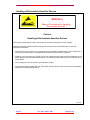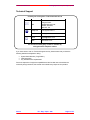
1
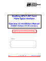
SeaKing SPLIT AIF Card
Fibre Optic Interface
Operator & Installation Manual
(SONV3 Software V1.50 and later)
The electronic version of this document is the controlled copy.
Therefore all printed versions of this document are uncontrolled.
Supplied by:
Issue 3
TIL – Eng – Spec – 025
SeaKing Split AIF Card OIM
COPYRIGHT
© Tritech International Ltd
The copyright in this document is the property of Tritech International
Limited. The document is supplied by Tritech International Limited on
the understanding that it may not be copied, used, or disclosed to
others except as authorised in writing by Tritech International Limited.
Tritech International Limited reserved the right to change, modify and
update designs and specifications as part of their ongoing product
development programme.
F063.1
Tritech International Ltd
SeaKing Split AIF Card (Fibre Optic I/F) OIM
TABLE OF CONTENTS
Handling of Electrostatic-Sensitive Devices ......................................................................................... 5
Technical Support .................................................................................................................................. 7
SEAKING SPLIT AIF CARD INTRODUCTION.............................................................................. 8
OPERATIONAL OVERVIEW ............................................................................................................ 8
SECTION A:........................................................................................................................................... 9
BENCH TEST SETUP FOR SPLIT AIF CARD .................................................................................. 9
SECTION B: ......................................................................................................................................... 11
INSTALLING SPLIT AIF FOR RS-232 COMMUNICATIONS ........................................................... 11
PART 1: SURFACE HARDWARE INSTALLATION.............................................................................. 11
PART 2: SUBSEA HARDWARE INSTALLATION ................................................................................ 12
SECTION C:......................................................................................................................................... 14
SOFTWARE SETUP FOR RS-232 OPERATION............................................................................. 14
SECTION D:......................................................................................................................................... 16
PART 1: USING AIFV4 FOR ARCNET OPERATION ................................................................... 16
PART 2: SOFTWARE SETUP FOR ARCNET OPERATION ......................................................... 17
PART 3: ARCNET BAUD RATE CHANGES ON AIFV4 CARD ................................................... 18
Issue 3
TIL – Eng – Spec – 025
Page 4 of 18
Tritech International Ltd
SeaKing Split AIF Card (Fibre Optic I/F) OIM
Handling of Electrostatic-Sensitive Devices
Attention
Observe Precautions for handling
Electrostatic Devices
Caution
Handling of Electrostatic-Sensitive Devices
Certain semiconductor devices used in the equipment are liable to damage due to static voltages.
Observe the following precautions when handling these devices in their unterminated state, or sub-units
containing these devices:
•
Persons removing sub-units from any equipment using electrostatic sensitive devices must be earthed by a
wrist strap via a 1MΩ resistor to a suitable discharge reference point within the equipment.
•
Soldering irons used during any repairs must be low voltage types with earthed tips and isolated from the
Mains voltage by a double insulated transformer. Care should be taken soldering any point that may have a
charge stored.
•
Outer clothing worn must be unable to generate static charges.
•
Printed Circuit Boards (PCBs) fitted with electrostatic sensitive devices must be stored and transported in
appropriate anti-static bags/containers.
F110.0
Issue 3
TIL – Eng – Spec – 025
Page 5 of 18
Tritech International Ltd
SeaKing Split AIF Card (Fibre Optic I/F) OIM
Warranty Statement
Tritech International Limited herein after referred to as TIL
TIL warrants that at the time of shipment all products shall be free from defects in material and workmanship and suitable
for the purpose specified in the product literature.
The unit/system warranty commences immediately from the date of customer acceptance and runs for a period of 365
days. Customer acceptance will always be deemed to have occurred within 72 hours of delivery.
Note: Any customer acceptance testing (if applicable) must be performed at either TIL premises or at one of their
approved distributors unless mutually agreed in writing prior to despatch.
Conditions:
These include, but are not limited to, the following:
1
The warranty is only deemed to be valid if the equipment was sold through TIL or one of its approved distributors.
2
The equipment must have been installed and commissioned in strict accordance with approved technical
standards and specifications and for the purpose that the system was designed.
3
The warranty is not transferable, except or as applies to Purchaser first then to client.
4
TIL must be notified immediately (in writing) of any suspected defect and if advised by TIL, the equipment subject
to the defect shall be returned by the customer to TIL, via a suitable mode of transportation and shall be freight
paid.
5
The warranty does not apply to defects that have been caused by failure to follow the recommended installation or
maintenance procedures. Or defects resulting from normal wear & tear, incorrect operation, fire, water ingress,
lightning damage or fluctuations in vehicles supply voltages, or from any other circumstances that may arise after
delivery that is outwith the control of TIL.
(Note: The warranty does not apply in the event where a defect has been caused by isolation incompatibilities.)
6
The warranty does not cover the transportation of personnel and per diem allowances relating to any repair or
replacement.
7
The warranty does not cover any direct, indirect, punitive, special consequential damages or any damages
whatsoever arising out of or connected with misuse of this product.
8
Any equipment or parts returned under warranty provisions will be returned to the customer freight prepaid by TIL
9
The warranty shall become invalid if the customer attempts to repair or modify the equipment without appropriate
written authority being first received from TIL.
10
TIL retains the sole right to accept or reject any warranty claim.
11
Each product is carefully examined and checked before it is shipped. It should therefore be visually and
operationally checked as soon as it is received. If it is damaged in anyway, a claim should be filed with the courier
and TIL notified of the damage.
Note: TIL reserve the right to change specifications at any time without notice and without any obligation to
incorporate new features in instruments previously sold.
Note: If the instrument is not covered by warranty, or if it is determined that the fault is caused by misuse, repair
will be billed to the customer, and an estimate submitted for customer approval before the commencement of
repairs.
F167.1
Issue 3
TIL – Eng – Spec – 025
Page 6 of 18
Tritech International Ltd
SeaKing Split AIF Card (Fibre Optic I/F) OIM
Technical Support
Contact your local agent or Tritech International Ltd
Mail
Tritech International Ltd.
Peregrine Road,
Westhill Business Park,
Westhill, Aberdeen,
AB32 6JL, UK
Telephone
++44 (0)1224 744111
Fax
++44 (0)1224 741771
Email
[email protected]
Web
www.tritech.co.uk
An out-of-hours emergency number is available by
calling the above telephone number
If you have cause to use our Technical Support service, please ensure that you have the
following details at hand prior to calling:
•
•
•
System Serial Number ( if applicable )
Fault Description
Any remedial action implemented
Due to the expansion of equipment capabilities and the fact that new sub-modules are
continually being introduced, this manual cannot detail every aspect of the operation.
Issue 3
TIL – Eng – Spec – 025
Page 7 of 18
Tritech International Ltd
SeaKing Split AIF Card (Fibre Optic I/F) OIM
SEAKING SPLIT AIF CARD INTRODUCTION
The Split AIF system is required when it is necessary to use a fibre optic system for
communications between the control unit and the subsea sensors.
This may be because a twisted pair is not available or if the cable length is too long to support
the high speed data link over conventional conductors (typically in excess of 1.5km)
This manual must be used in conjunction with other system manuals supplied with the
system.
The Split AIF Fibre Optic interface consists of two boards’ one inside the SCU (AIFV4) and
one board on the subsea end of the fibre optic system (SA AIF).
Note: The older style AIFBV3 card can be used when upgrading an existing system.
Definitions:
SA AIF
AIFV4
Stand Alone Acoustic Interface – Locates in the dry pod subsea.
Acoustic Interface Version 4 – Locates inside the Surface Control Unit.
(The AIFBV3 card can be used as a direct replacement if Software version
1.50 or above is used)
OPERATIONAL OVERVIEW
The Split AIF Interface can be utilised in two ways.
1. By making use of both AIFV4 and SA AIF cards, the system can be configured for RS232 communications between cards (for interface to an RS232 fibre optic MUX) and then
ARCNET between the subsea card and multiple heads.
SONAR/PROFILER
HEAD
SEAKING SCU
RS-232
FIBRE OPTIC
SA AIF
CARD
AIF V4
CARD
SURFACE
COMMUNICATIONS
CARD
ARCNET
FIBRE-OPTIC
TX/RX
SUBSEA
COMMUNICATIONS
CARD
2.
Diagram 1.01: General Layout for RS232 operation.
Issue 3
TIL – Eng – Spec – 025
Page 8 of 18
Tritech International Ltd
SeaKing Split AIF Card (Fibre Optic I/F) OIM
3. Using only the surface AIFV4 card, the system can be configured for ARCNET and will
run multiple heads through a single copper twisted pair of up to 2500 metres in length.
Diagram 1.02: General Layout for ARCNET operation (Using AIFV4 only)
SEAKING SCU
ARCNET: Useable through
twisted pair up to 2.5km in length
SONAR/PROFILER
HEAD
AIF V4
CARD
SURFACE
COMMUNICATIONS
CARD
SECTION A:
BENCH TEST SETUP FOR SPLIT AIF CARD
In order to set up the Split AIF RS-232 communications it is important that the following
procedure is followed closely as failure to do so may result in permanent communication
loss to the SA AIF.
To initially configure and test the Split AIF system it is advisable to first set the system up on a
bench, connecting the SA AIF PCB directly to the AIFV4 card.
1) For powering the SA AIF PCB, a power supply cable has been included and this will
connect to the +12 V DC supply output (banana plug sockets) situated on the rear of the
SCU.
2) RS-232 I/O on both the AIFV4 and SA AIF cards is on their respective AUX-IDC ports.
For interconnection, wire a short NULL modem RS-232 cable, as follows:
AIFV4 – AUX-IDC
(9-way M ‘D’)
SA AIF – AUX-IDC
(9-way M ‘D’)
2--------------------------------------------------3
3--------------------------------------------------2
5--------------------------------------------------5
1
1
2
2
AIFV4 'J8'
SA AIF 'J4'
RS232 links
• IDC wiring pin-outs
Issue 3
TIL – Eng – Spec – 025
Page 9 of 18
Tritech International Ltd
SeaKing Split AIF Card (Fibre Optic I/F) OIM
The full bench wired configuration is as follows;
SEAKING SCU
68 ohm
termination
i t
ARCNET-A
<Head pin-1>
J8 (AUX-IDC)
ARCNET-B
<Head pin-2>
1
J6
J5
1
1
+12 to 24VDC
4
GND
J4 (AUX-IDC)
1
SA AIF
Card
AIFV4
Card
'J2.3'
9-way
M 'D'
Null Modem
9-way
F 'D'
RS-232
9-way
F 'D'
9-way
M 'D'
ARCNET-A
1
2
ARCNET-B
'J6'
Diagram 1.03: Bench Wiring
Refer to Section C of this manual for software configuration, including selection of
RS-232 Baud rates.
Issue 3
TIL – Eng – Spec – 025
Page 10 of 18
Tritech International Ltd
SeaKing Split AIF Card (Fibre Optic I/F) OIM
SECTION B:
INSTALLING SPLIT AIF FOR RS-232 COMMUNICATIONS
PART 1: SURFACE HARDWARE INSTALLATION
The surface AIFV4 card is fitted inside the SeaKing SCU (Surface Control Unit) or PC in the
case of a PC Kit. The existing AIFV3 card can be used if an upgrade package is supplied.
Inside the SCU, the ribbon cable from the RAT connects to J9 (RAT-IDC). The ribbon cable
from the 10-way COM2 header on the motherboard connects to J11 (RATCOM-PIN) or to J10
(RATCOM-IDC) in unique cases. When fitting to a PC, the J9 header is not used.
Using the RAT Extension lead supplied with the SCU, the RAT can also connect to J5 which
is the 9-way ‘D’ type port on the backplane of the card.
A SCU backplane plate with 9-way ‘D’ male and ribbon connector is supplied with the system.
This fits inside the SCU in an adjacent slot to the AIFV4 card and is J2.3 on the SCU. The
ribbon cable from this plate plugs into J8 (AUX-IDC) on the AIFV4 card*.
RS-232 communications to the Fibre Optic MUX is now made through J2.3.(see diagram
1.04).
Pin-outs are as below:
J2.3 – 9D Male pin allocations
2
----------------------------------- RS-232 Uplink data. (Yellow)
3
----------------------------------- RS-232 Downlink data. (Blue)
5
----------------------------------- RS-232 Ground. (Screen)
ARCNET output Connector
RAT Extension Connector
J2.2
J2.1
Expansion Slots
Slot 7
Sonar AIFV4 Card
J2.3
RS232 output from AIFV4
Card
Slot 6
May be used for PORT 2 & PORT3
Slot 5
Slot 4
J3.1
VGA Card
Slot 3
J1.1
PORT 1
Slot 2
Multi IO Card
Can be used to bench
power SA AIF
Optional 12V for video O/P
Slot 1
J5
J1
J2
SCU3BCK2
Diagram 1.04: Rear view of SCU with AIFV4 Fitted
Issue 3
TIL – Eng – Spec – 025
Page 11 of 18
Tritech International Ltd
SeaKing Split AIF Card (Fibre Optic I/F) OIM
PART 2: SUBSEA HARDWARE INSTALLATION
The subsea SA AIF PCB should be fitted as near as possible to the subsea FO MUX.
This card has one power connector; J5.
A mating connector is supplied and +12 to +24 Volts DC (max) must be applied.
There are three data connectors; J3, J4, J6 (J3 is unused).
Two ribbon connectors are supplied, one 9-way D male and one 15-D female.
The 9-way ribbon connects to J4 (AUX IDC) this is used for RS-232 communications to the
Fibre Optic MUX. See diagrams 1.03 & 1.11 for exact pin-outs.
The 15-way ribbon connects to J6 (LAN-IDC) this is used for ARCNET communications to the
SeaKing sensors. See diagram 1.11.
The 15-way ‘D’ pin-outs are exactly the same as for J3 on the original Tritech AIFBV3 card
(see the main SeaKing system manual). However, ONLY pins 8 and 15 (ARCNET) on the
15-way ‘D’ should be connected on the SA AIF output.
A termination resistor is required and should be a single 68 ohms when the ARCNET circuit
is less than 100metres in length.
SA AIF CARD - 'SW1'
ON
1
2
Switch 1: ON = Normal *
OFF = Boot
Switch 2: OFF= Normal Baud ON = Half Baud
* factory setting - do not touch
Switches
CPU
J3
J3 Not
Connected
9-way ‘D’
J4
J5
Pin 4
J6
Pin8 – ARCNET-A (to Heads Pin 1)
Pin15 – ARCNET-B (to Heads Pin 2)
Fit a single 68ohm resistor anywhere
between ARCNET-A and ARCNET-B. This
will terminate the entire ARCNET circuit.
Gnd
Diagram 1.11: "Split AIF" subsea card (SA AIF) power and data connections
Issue 3
To Subsea
Fibre Optic
Mux
15-way ‘D’
Pin 1
+12 to 24 VDC
Pin3 - RS232 Uplink (Blu)
Pin2 - RS232 Downlink (Yel)
Pin5 - RS232 Ground (Scrn)
TIL – Eng – Spec – 025
Page 12 of 18
Tritech International Ltd
SeaKing Split AIF Card (Fibre Optic I/F) OIM
118mm
6.5mm
3mm Diameter
holes
J3
7mm
105mm
114.6mm
J4
J6
127.5mm
Diagram 1.12: "Split AIF" subsea card (SA AIF) dimensions.
Issue 3
TIL – Eng – Spec – 025
Page 13 of 18
Tritech International Ltd
SeaKing Split AIF Card (Fibre Optic I/F) OIM
SECTION C:
SOFTWARE SETUP FOR RS-232 OPERATION
(Software version 1.50 and above)
Use BENCH TEST SETUP FOR SPLIT AIF CARD described previously
Switch on the power to the SCU and this will also supply +12 VDC to the SA AIF card.
Close the SONV3 software and load V3Setup by clicking on it’s Windows Program Icon.
The following Table will appear:
IF NODE 254 DOES NOT APPEAR
ESTABLISH COMMUNICATIONS USING (RECOVERY) 9600 BAUD SPEED, as below
Press the Program User Data button.
The AIF SETUP panel appears as below:
Uncheck the Aif V4 Hi Speed check box.
Press Exit and Program on request.
Once the program is complete shut down V3setup.
Switch off power to the SA AIF and set it’s ‘SW1’ Switch-2 to ON position.
Switch power to the SA AIF back on.
Restart V3SETUP and press Rebuild.
The SA AIF card should now appear as NODE 254 using the (recovery) RS-232
communications rate of 9600 baud.
Issue 3
TIL – Eng – Spec – 025
Page 14 of 18
Tritech International Ltd
SeaKing Split AIF Card (Fibre Optic I/F) OIM
SETTING FIBRE LINK SPEED Step 1: Subsea Interface – SA AIF
Select Node 254
Press Program User Data button, then Baud rates
The following panel appears:
Locate the settings for Async 0 channel and set right-hand baud rate to desired Fibre
link speed (default speed is 115.2 kBaud*).
* speeds less than 38.4k are unadvisable for imaging sonar applications
Press Exit and Program Node 254 when prompted.
SETTING FIBRE LINK SPEED Step 2: Surface Interface – AIFV4
Select Node 255
Press the Program User data button again, then press Baud rates.
The following panel appears
Locate the settings for Async 0 channel and set right-hand baud rate to desired Fibre
link speed. This should match the SA AIF link speed setting (default speed is 115.2
kBaud*).
* speeds less than 38.4k are unadvisable for imaging sonar applications.
Press Exit and check AIF V4 Hi Speed check box, if unchecked.
Press Exit and Program Node 255 when prompted.
Switch off power to the SA AIF and set it’s ‘SW1’ Switch-2 to OFF.
Switch power back on.
Restart V3SETUP and press Rebuild. NODES 255 & 254 should now appear.
The RS-232 link is now running at the Async 0 right-hand Baud speed (as
shown in the above panel) and the Split AIF system is now ready to be
integrated with the Fibre Optic system as per the Hardware Installation
described previously.
Issue 3
TIL – Eng – Spec – 025
Page 15 of 18
Tritech International Ltd
SeaKing Split AIF Card (Fibre Optic I/F) OIM
SECTION D:
PART 1: USING AIFV4 FOR ARCNET OPERATION
HARDWARE INSTALLATION
The Hardware installation is the same as for the standard AIFBV3 card.
The ARCNET output is now from pins 8 and 15 on the AIFV4 card’s J2.1 connector
(See diagram 1.21 & 1.22)
TERMINATION
ARCNET impedance termination is 270 ohms at the surface and 39ohms subsea (i.e.
Standard SeaKing ARCNET resistor values)
WARNING: The AIF mating connector may be supplied fitted with a lower value resistor
intended for use with the Split AIF RS232 configuration, this must be checked and changed if
incorrect.
Termination:
surface : 270 ohms
subsea : 39 ohms
J2.2
AIF V4 Card
Pin 8 : ARCNET A (To heads pin 1)
J2.1
Pin 15 : ARCNET B (To heads pin 2)
Diagram 1.21: AIFV4 ARCNET Connections.
Issue 3
TIL – Eng – Spec – 025
Page 16 of 18
Tritech International Ltd
SeaKing Split AIF Card (Fibre Optic I/F) OIM
ARCNET output Connector
RAT Extension Connector
J2.2
J2.1
Expansion Slots
Slot 7
Sonar AIFV4 Card
J2.3
RS232 I/O from AIFV4
Card
Slot 6
May be used for PORT 2 & PORT3
Slot 5
Slot 4
J3.1
VGA Card
Slot 3
J1.1
PORT 1
Multi IO Card
Can be used to bench
power SA AIF
Slot 2
Slot 1
Optional 12V for video O/P
J5
J1
J2
SCU3BCK2
Diagram 1.22: Rear view of SCU showing AIFV4 ARCNET connection J2.1
PART 2: SOFTWARE SETUP FOR ARCNET OPERATION
(Software version 1.50 and above)
The AIFV4 card operates under ARCNET exactly the same as the AIFBV3 card, with
an exception that is detailed on Part 3.
The card is capable of communicating through J2.3 to the SA AIF card AND through
J2.1 directly to heads using ARCNET SIMULTANEOUSLY.
Therefore there is no further software settings required to operate a network directly
through twisted pair.
Issue 3
TIL – Eng – Spec – 025
Page 17 of 18
Tritech International Ltd
SeaKing Split AIF Card (Fibre Optic I/F) OIM
PART 3: ARCNET BAUD RATE CHANGES ON AIFV4 CARD
I) On an AIFBV3 card there is a hardware switch to select between half baud (78kb) and Full
baud (156kb).
II) On the AIFV4 card this is done in software as follows.
Run V3SETUP
Press Program V4 AIF
This will bring up the following panel:
The Aif V4 Hi Speed check box replaces the hardware switch.
With the box checked the system will run at 156 kbit/s.
With the box unchecked the comms will be 78 kbit/s.
Issue 3
TIL – Eng – Spec – 025
Page 18 of 18