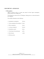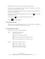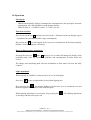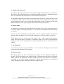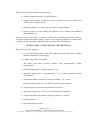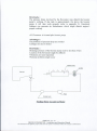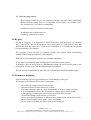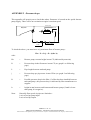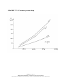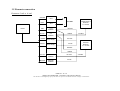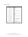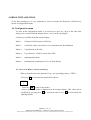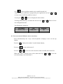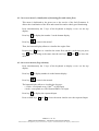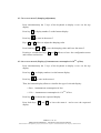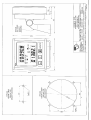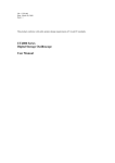
1
OPERATION AND INSTALLATION
MANUAL
00MU013-B
IND.
A
B
Author
IQ
Date
2000
30/03/06
Description
Initial Version
Photo, sensor coefficient, drwg B2369 added, formatting.
00MU013 - B - 2
ORION ECONOMETER – Installation and Operation Manual
This document is I2E Diffusion property and cannot be copied or transmitted without the company’s authorization.
SOMMAIRE
1 DESCRIPTION - OPERATION .................................................................................................................................. 4
1.1 DESCRIPTION ................................................................................................................................................................. 4
1.2 EXTERNAL CONNECTION ................................................................................................................................................ 5
1.3 TECHNICAL CHARACTERISTICS ...................................................................................................................................... 5
1.4 OPERATION .................................................................................................................................................................... 6
2 FUEL FLOWMETERS ................................................................................................................................................ 7
2.1 FUEL CIRCUIT ................................................................................................................................................................ 7
2.2 SPECIFIC CONSUMPTION .............................................................................................................................................. 11
2.3 FLOWMETER LOCATION ............................................................................................................................................... 11
2.3.1 Short return ......................................................................................................................................................... 11
2.3.2 Standard injection with return to day tank .......................................................................................................... 12
2.3.3 Injector pump engine ........................................................................................................................................... 15
2.4 BY-PASS ...................................................................................................................................................................... 15
2.5 FLOWMETERS MOUNTING ............................................................................................................................................ 15
2.6 SENSOR DISMANTLING ................................................................................................................................................. 16
APPENDIX 1 : FUEL SPECIFICATIONS............................................................................................................................... 17
APPENDIX 2 : PRESSURE DROPS...................................................................................................................................... 18
GRAPHIC N°1 : FLOWMETER PRESSURE DROP ................................................................................................................. 19
GRAPHIC N°2 : PRESSURE DROP IN PIPES PER FLOWMETER ............................................................................................. 20
EXAMPLES ......................................................................................................................................................................... 21
3 INSTALLATION......................................................................................................................................................... 23
3.1 CABINET MECHANICAL INSTALLATION ........................................................................................................................ 23
3.2 FUEL FLOWMETER MECHANICAL INSTALLATION .......................................................................................................... 23
3.3 FUEL FLOWMETER SENSITIVITY ................................................................................................................................... 23
3.4 INPUTS/OUTPUTS ADJUSTMENT .................................................................................................................................... 24
3.5 FLOWMETER CONNECTION ........................................................................................................................................... 25
3.6 WIRES DESCRIPTION .................................................................................................................................................... 26
4 ORION INITIALIZATION........................................................................................................................................ 27
4.1 CONFIGURATION MENU................................................................................................................................................ 27
4.1.1 Access to Menu 1 (sensor sensitivity) .................................................................................................................. 27
4.1.2 Access to menu 2 (Return sensor correction) ...................................................................................................... 28
4.1.3 Access to menu 3 (visualization of incoming flow and return flow) .................................................................... 29
4.1.4 Access to menu 4 (Log selection)......................................................................................................................... 29
4.1.5 Access to menu 5 (damping adjustment) ............................................................................................................. 30
4.1.6 Access to menu 6 (Display of instantaneous consumption in 10ème of liter) ........................................................ 30
5 ERROR MESSAGES .................................................................................................................................................. 31
DRAWINGS LIST.......................................................................................................................................................... 32
00MU013 - B - 3
ORION ECONOMETER – Installation and Operation Manual
This document is I2E Diffusion property and cannot be copied or transmitted without the company’s authorization.
1 DESCRIPTION - OPERATION
1.1 Description
ORION econometer allows to measure and control the diesel engine consumption,
onboard commercial or fishing boats.
The information are shown on two LCD displays, allowing the user to chose the function
to be displayed.
The available information are the following :
¾ Instantaneous consumption
(l/hour)
¾ Total consumption from starting up (liters)
¾ Daily consumption
(liters)
¾ Average consumption
(l/hour)
¾ Instantaneous speed
(knot)
¾ Total distance from starting up
(mile)
¾ Daily distance
(mile)
¾ Efficiency factor
00MU013 - B - 4
ORION ECONOMETER – Installation and Operation Manual
This document is I2E Diffusion property and cannot be copied or transmitted without the company’s authorization.
Display function is defined on six leds located between the two displays.
The first 3 leds corresponding to speed functions, instantaneous and adverage
consumption are dedicated to the top display.
The last 3 leds corresponding to distance functions, consumption and efficiency factor are
dedicated to the bottom display.
The display selection is made through the keyboard. The central key Ç allows to change
the top display functions
The key on the left ← allows to change the bottom display functions
The key
allows light adjustment.
1.2 External connection
The feed in of a speed information given by a log or a GPS allows the ORION to
calculate the vessel’s efficiency coefficient (efficiency factor).
1.3 Technical characteristics
Power supply : 12 V to 24 V continue (100mA max).
Inputs :
1 input for power supply sensor
1 input for return sensor
1 log input 1/200ème of mille (dry contact)
or
1 RS422 input format NMEA183 for GPS Speed receipt
or
1 RS232 input format NMEA183 for GPS Speed receipt.
Outputs :
1 output liter counting (dry contact)
or
1 RS422 output - NMEA183 format
or
1 RS232 output – NMEA 183 format
1 output for fuel sensor power supply.
00MU013 - B - 5
ORION ECONOMETER – Installation and Operation Manual
This document is I2E Diffusion property and cannot be copied or transmitted without the company’s authorization.
1.4 Operation
Starting up
− ORION automatically displays instantaneous consumption on the top display and total
consumption since the installation on the bottom display.
− LEDs in front of « CONS l/h » and « T. CONS » are on.
Functions selection
Press by fits on the key ↑ displays successively the 3 functions on the top display (speed
– instantaneous consumption and average consumption).
By pressing key ← you will display by fits successive information on the bottom display
(distance, total consumption, efficiency).
Reset of distance and consumption
Pressing the two keys
and ← during a few seconds will change the display from
totalizing mode since the installation (distance and consumption) to daily mode and
reverse.
The change from totalizing mode since the installation to daily mode will reset the daily
counters.
Light adjustment
When starting up, ORION is on day mode (Led on, no back light).
Press key
to pass in night mode (led on, Back-lighting on).
, the display lighting will decrease up to a minimum level and
Keep pressing key
then start again at maximum level to decrease again.
When lighting adjustment is convenient, stop pressing key
is stored up and kept after power off.
. The lighting adjustment
00MU013 - B - 6
ORION ECONOMETER – Installation and Operation Manual
This document is I2E Diffusion property and cannot be copied or transmitted without the company’s authorization.
2 FUEL FLOWMETERS
Where and how should the flowmeter be installed ?
-
In a location without vibrations,
After a 40µ max. filter,
On pipes as short as possible,
If the day tank is located at 2 meters above the 5cm3 sensor
- Before the booster pump
- If the days tank is located lowest :
- Place sensor after the booster pump (if the pump pressure is less than 5 bars)
- Before the booster pump (if there is an electrical recirclation pump).
- It is strongly recommended to use a manual or automatic bypass.
2.1 Fuel circuit
(REFER TO SCHEMATIC DIAGRAM page 9)
The purpose of this paragraph is to explain the main features of fuel circuits on diesel
engines ; as well as the vocabulary description of the different specific functions.
Generally, a standard fuel circuit as shown at the end of this paragraph, is comprised of
the following elements :
1- Storage tanks
Also called fuel compartments or store-room, or ballast. Generally, they are filled with
enough diesel oil for the trip. Usually, there are at least 2 tanks. Each tank has a level
control device that may be used for econometer calibration.
2- Prefilter
Placed at the input of the feed pump, it prevents the feed pump to be damaged by particles
coming from the storage tank. Smallness is between 200 and 40 microns.
3- Feeding pump
Also called transfer pump. It pumps from storage tank and descharges in settling tank. It
can be driven by the engine or can be part of it. It is a piston or gear pump.
4- Settling filter
It is located at the supply pump delivery, in order that settling tank be filled with clean
fuel (without water). Smallness is about 10 microns. Today modern centrifugal diesel oil
separators are prefered.
00MU013 - B - 7
ORION ECONOMETER – Installation and Operation Manual
This document is I2E Diffusion property and cannot be copied or transmitted without the company’s authorization.
5- Settling tank (Day tank)
It feeds the engine directly and is not necessarily charged. Sometimes, it is a division of
the storage. On small ships it may even replace the tanks. In that case, feed pump and pre
filter are eliminated and settling filter is located behind settling tank.
In standard installations (with tanks), settling tank must always be entirely filled (to avoid
condensation). Day tank allows removing of gas vapors and cooling fuel coming from
return flowmeter. In the case of booster pump defection, when it is charged, the day tank
theoretically ensures the engine supply with clean fuel during many hours.
6- Booster pump
As indicated, it feeds the injection pump body with diesel oil. Its flow is always superior
or equal to engine consumption (usually 1.3 to 4 times the consumption and sometimes up
to 5 times).
It draws up from settling tank and discharges into the injection pump(s). Its pressure
depends on the discharge valve of injection pump (from 1 to 2 bars, and up to 20 bars).
The discharge value is usually part of the engine, and is often coupled with injection
pump. The booster pump is generally a volumetric pump, so its flow is proportional to
engine r.p.m. It can be a gear, piston or membrane pump (in the last two cases, flow is
pulsed).
7- The Main filter
It protects the injection pump. Smallness is a few microns. Nothing must be located
between the filter and the injection pump.
8- Injection pump
This pump injects the fuel consumed by the engine into the cylinders through the
injectors. Its flow depends on the rotation speed of engine and on the position of throttle
which controls the adjustment elements inside the pump. This throttle is sometimes
controlled by a governor which maintains the engine speed rotation at a determined
speed. Discharge pressure depends on injectors rating pressure.
00MU013 - B - 8
ORION ECONOMETER – Installation and Operation Manual
This document is I2E Diffusion property and cannot be copied or transmitted without the company’s authorization.
FUEL CIRCUIT : SCHEMATIC DIAGRAM
00MU013 - B - 9
ORION ECONOMETER – Installation and Operation Manual
This document is I2E Diffusion property and cannot be copied or transmitted without the company’s authorization.
There are four possible injection pump systems :
• Rotative pumps (especially on small engines)
• Pumps in line (usually located between the cylinder-covers and V moters and
the inlet side for linear motors).
• Individual pumps i.e. one pump per cylinder (on large engines)
• Injector pumps, for each cylinder, the cylinder-cover is made up of combined
pump and injector.
Except in some cases, there is always a return flow, generally towards day tank or
sometimes towards the booster pump’s section. This return corresponds to booster pump
overflow VS the consumption which depends on engine load, which means :
SUPPLY FLOW = CONSUMPTION + RETURN FLOW
Return flow has other purposes :
• It cools the injection pump - this means that return fuel temperature is higher
than the temperature of fuel supply.
• It drains off possible air bubbles.
The above first three injection systems, have approximately similar
specifications :
• Booster pump pressure = approximately 1.5 bar
• Maximum supply flow = approximately 1.3 to 4 times maximum engine
consumption.
• Temperature difference between supply and return = 10° to 20°C.
Injector-pump systems have very different working specifications :
• Supply pressure of booster pump is about 5 to 20 bars
• Maximum supply flow = 4 to 5 times of maximum consumption
• Temperature difference between supply and return 30° to 40°C.
• Liquid emulsion.
• Important steam on return.
00MU013 - B - 10
ORION ECONOMETER – Installation and Operation Manual
This document is I2E Diffusion property and cannot be copied or transmitted without the company’s authorization.
2.3.2 Standard injection with return to day tank
Two solutions must be eliminated : a flowmeter located at upside of day tank , and
a flowmeter on the leakage of tank. Because, level variations can not be avoided,
would give errors of the instantaneous flow measurement.
Therefore, two flowmeters are necessary between day tank and injection pump, one
on supply flow and the other one on return.
A/ Supply flowmeter
First make sure that either a 40 microns mesh size filter will protect the flowmeter,
or the day tank will be filled through a centrifugal separator. If not, change the
settling filter’s cartridge or add a 40 microns filter.
Two solutions are possible :
A1/ The flowmeter is located before the booster pump
This avoids installation of the flowmeter on the engine.
Advantages :
No engine vibration
Minimum flow pulses
No problem concerning pressure rating of the flowmeter
There is more place available for flowmeter location.
Day tank
2µ filter
Injection pump
return
Booster pump
Supply meter upstream engine fuel input
00MU013 - B - 12
ORION ECONOMETER – Installation and Operation Manual
This document is I2E Diffusion property and cannot be copied or transmitted without the company’s authorization.
B/ Flowmeter on return to day tank line
In this case too, it is better to avoid flowmeter location on the engine (vibration and
temperature). Make sure that flowmeter installation and its by-pass do not create
problems.
If an emulsion on return appears due to unfavorable conditons (high booster pump
pressure, and high return temperature), it is possible to install a tare valve behind
the return flowmeter. This valve’s pressure is less than the pressure of the injection
pump’s outlet-valve, (in any case less than 5 bars). It will be necessary to check if
existing pipes between added valve and injection pump can resist to adjusting
pressure.
Day tank
Return meter
2µ filter
Supply meter
Injection pump
Booster pump
Return flowmeter location
00MU013 - B - 14
ORION ECONOMETER – Installation and Operation Manual
This document is I2E Diffusion property and cannot be copied or transmitted without the company’s authorization.
2.3.3 Injector pump engine
These engines usually involve very difficult problems. Return is often emulsifying.
Moreover booster pump flow is very important which requires, for example, use a
500 l/h sensor for a 100 l/h fuel consumption.
It will be necessary to install on return either :
an adjusted valve behind sensor or
a degasing system before sensor.
2.4 By-pass
For safety purposes, it is suggested to install flowmeters with by-passes (see drawing
A4737 and A4738), that can be opened in case of emergency, if a solid particle (more that
40 microns) lock the sensor gears. Upon sensor installation, it is recommended to pen the
by-passes during a few minutes.
The complete 3-valve by-pass (see drawing A4738) also permits sensor dismounting
without neither stopping engine nor emptying pipe.
However, by-pass utilization requires two minimum checkings :
If a by-pass is open during usual working, the measurement will be wrong.
If the three valves of the by-pass are simultaneous turned off, and if booster pump is not
protected by a outlet-valve, the installation might be damaged.
We can provide an automatic by-pass that can be manually controlled from the bridge.
2.5 Flowmeters mounting
Sensor mounting requires a great attention to avoid damage on the gears.
We strongly recommend to follow these instructions :
o
o
o
o
o
o
o
o
o
Never blow-in compressed air into the pipes
Flowmeter front face must always be vertical
Flowmeter front face must be easily dismountable in order to reach oval gears
It is recommended to locate the flowmeter by adjacent pipes (do not strain).
Upon tighting of connectors, the flowmeter must be held by its ends
Avoid brass fittings, prefer bronze or inox ones.
Do not use teflon for tightness as teflon particles could spread and lock the sensor
Before final mounting, check pipes, valves and fittings.
Do not forget to open the by-passes upon initial starting up.
00MU013 - B - 15
ORION ECONOMETER – Installation and Operation Manual
This document is I2E Diffusion property and cannot be copied or transmitted without the company’s authorization.
2.6 Sensor dismantling
1- Spot the emplacement of each sensor and its axis positioning (high-low)
2- The gearings are joined to the tank
3- Clean every tooth with a brush
4- Clean with a cotton rag and fuel the socket
5- Do not forget to clean the cap
6- Never blow in the sensor.
00MU013 - B - 16
ORION ECONOMETER – Installation and Operation Manual
This document is I2E Diffusion property and cannot be copied or transmitted without the company’s authorization.
APPENDIX 1 : Fuel specifications
Voluminal mass = 0.83
< 0.89 at 15°C
Viscosity :
< 7 cSt at 40°C
<13 cSt at 40°C
- Gaz oil
- Marine Diesel oil
Types and standards :
COUNTRY
TYPES
STANDARDS
FRANCE
Gazoil
Domestic fuel
Marine diesel oil
NF-M-15007
NF-M-15008
GREAT BRITAIN
A1 and A2 categories
BS2869
GERMANY
Heiz oel el
DIN51603
U.S.A.
1 and 2 fuel
ASTM D 396
00MU013 - B - 17
ORION ECONOMETER – Installation and Operation Manual
This document is I2E Diffusion property and cannot be copied or transmitted without the company’s authorization.
APPENDIX 2 : Pressure drops
This appendix will permit you to check that where flowmeter is located on the upside booster
pump supply. There will be no cavitation at engine’s maxium speed.
Injection pump
Day tank
2 µ filter
h
C
Booster pump
Probe
To check the above, you must have at Q maximum flow of booster pump :
Ha > Pc + Lxj + Pf - (0,8 x h)
with :
Ha
=
Booster pump vacuum height in mm CE (indicated by motorist)
Pc
=
Pressure drop in the flowmeter in mm CE (see graph 1 on following
page)
L
=
Pipe length between tank and pump
j
=
Pressure drop per pipe meter in mm CE/m (see graph 2 on following
page)
Pf
=
Possible pressure drop in the filter, if a filter has been installed between
tank and pump ; this pressure drop is indicated by filter manufacturer or
supplier
h
=
height in mm between tank bottom and booster pump (if tank is lower
than pump, h is negative).
Nota :
Generally flow speeds in pipes are limited to :
1 m/s at feed up pump input
2 m/s at feed up output.
00MU013 - B - 18
ORION ECONOMETER – Installation and Operation Manual
This document is I2E Diffusion property and cannot be copied or transmitted without the company’s authorization.
GRAPHIC N°1 : Flowmeter pressure drop
00MU013 - B - 19
ORION ECONOMETER – Installation and Operation Manual
This document is I2E Diffusion property and cannot be copied or transmitted without the company’s authorization.
GRAPHIC N°2 : Pressure drop in pipes per flowmeter
Cinematic Viscosity : 5 cSt
00MU013 - B - 20
ORION ECONOMETER – Installation and Operation Manual
This document is I2E Diffusion property and cannot be copied or transmitted without the company’s authorization.
B/ Second installation type
Maximum sucking up height : l,3 m CE
Day
Tank
200 l/h
C
Booster pump
sensor
H=0
Pressure drop in filter for 200 l/h
0.5 mm CE
Piping between tank and engine
Piping on engine
diam. 12
diam. 12
Graph number 1 indicates for 200 l/h
Pc = 480 mm CE
Graph number 2 indicates for 200 l/h
diam.12
L = 10 m
L = 3m
j = 60 mm CE
Pc + LxJ + Pf = 480 + 13x60 + 500 = 1760 mm CE
Consequently, flowmeter must be installed at the booster pump discharge as maximum height is
overpassed (1760 mm CE FOR 1.3 CF).
00MU013 - B - 22
ORION ECONOMETER – Installation and Operation Manual
This document is I2E Diffusion property and cannot be copied or transmitted without the company’s authorization.
3 INSTALLATION
3.1 Cabinet mechanical installation
ORION Cabinet can be wall or bracket mouting according to drawing n° F 0236-M
3.2 Fuel flowmeter mechanical installation
ORION econometer can be connected with :
-
Flowmeter 5cm3 ref PVBEN203 with max. flow of 500 l/h see dwg. B 2368
Flowmeter 16cm3 ref PVBEN204 with max flow of 1200 l/h see dwb B 2369
3.3 Fuel flowmeter sensitivity
The sensor sensitivity must be enter in the ORION menu
Description
Sensor 5 cm3
Sensro 16 cm3
Référence
PVBEN203
PVBEN204
Sensitivity
400 T/L
250 T/L
00MU013 - B - 23
ORION ECONOMETER – Installation and Operation Manual
This document is I2E Diffusion property and cannot be copied or transmitted without the company’s authorization.
3.4 Inputs/outputs adjustment
ORION is factory adjusted to deliver the consumption information (dry contact) in output
and to receive 1/200ème of mile contacts from the log.
In case additional input/outputs are requested, it is necessary to open the Orion cabinet
and to change position of the straps on the main Pcb according to the following :
Function
Strap
Output RS 422
Output RS 232
S 1.1 – E3 – E 11
S 1.2 – E1 – E12
Input RS 422
Input RS 232
Input 1/200
S 2.1 – E6 – E8
S 2.2 – E4 – E9
E5 – E7
Counter input
E2 – E10
00MU013 - B - 24
ORION ECONOMETER – Installation and Operation Manual
This document is I2E Diffusion property and cannot be copied or transmitted without the company’s authorization.
3.5 Flowmeter connection
Flowmeter 5 cm3 or 16 cm3
ORANGE
+ BAT
+
BATTERY
GREY
ORION
- BAT
-
RED
+ 12 V
SENSOR
BROWN
BLACK
OV
SENSOR
GREEN
GREEN
PURPLE
POWER SUPPLY
SENSOR
5 or 16CM3
Sensor
Power Supply
YELLOW
Sensor
Power Supply
WHITE
4 WIRES
RETURN
SENSOR
5 or 16 CM3
BROWN
GREEN
YELLOW
RETURN
SENSOR
YELLOW
BROWN
RETURN
SENSOR
WHITE
4 WIRES
00MU013 - B - 25
ORION ECONOMETER – Installation and Operation Manual
This document is I2E Diffusion property and cannot be copied or transmitted without the company’s authorization.
3.6 Wires description
Wires
Description
Orange (Orange)
+ battery
Grey (Gris)
- battery
Red (Rouge)
}
}flowmeter power supply
}
Black (Noir)
Green (Vert)
Purple (Violet)
Yellow (Jaune)
Brown (Marron)
Blue (Bleu)
White (Blanc)
Bc blue (Bc bleu)
Bc Yellow (Bc jaune)
}
}Flowmeter power signal
}(amont)
}
}flowmeter return signal (aval)
}
+}
} input RS422 or RS232
- } or 1/200ème of mile
+}
} Output RS422 or RS232
- }or total (liters)
00MU013 - B - 26
ORION ECONOMETER – Installation and Operation Manual
This document is I2E Diffusion property and cannot be copied or transmitted without the company’s authorization.
4 ORION INITIALIZATION
At the first starting-up, it is very important to enter in memory the flowmeter coefficient by
means of configuration menu.
4.1 Configuration menu
To enter in the configuration menu, it is necessary to press on 3 keys at the same time
during a few seconds until the display shows « test » on the top display.
5 menus are available from the bottom display :
Menu 1 :
Change of the flowmeter coefficient
Menu 2 :
return flow value correction in % to compensate the fuel dilatation
Menu 3 :
Visualization of the flow
Menu 4 :
Log selection : 1/200ème of mile from GPS
Menu 5 :
damping adjustment
Menu 6 :
Instantaneous consumption (10ème of liter) display
4.1.1 Access to Menu 1 (sensor sensitivity)
When you push at the same time the 3 keys , the top display shows « TEST »
- Press key Ï to increment the menu until it shows
TEST
1
- Press key
to enter in the menu 1.
- Sensor coefficient value is displayed on the bottom display. This value can be
modified by pressing key Ï to increment and on key Í to discrement the
lighting number.
00MU013 - B - 27
ORION ECONOMETER – Installation and Operation Manual
This document is I2E Diffusion property and cannot be copied or transmitted without the company’s authorization.
Key
is used to shift the number to be modified to the left.
Once the sensor coeffficient is programed, press together the two keys Í and Ï
to save sensor coefficient and leave menu 1.
Pressing key Í or Ï allows to display the others menus.
Pressing simultaneously a second time the two keys Í and Ï allows to leave
the configuration menu.
Fuel flowmeter sensitivity.
Description
Sensor 5 cm3
Sensor 16 cm3
Code
PVBEN203
PVBEN204
coefficient
400
250
4.1.2 Access to menu 2 (Return sensor correction)
Press simultaneously the 3 keys of the keyboard to display « test » on the top
display.
Press key Ï to display the number 2 on the bottom display.
Press key
to enter in the menu 2.
Press key Í or Ï to write in % the correction value to modify the return flow.
When this value is entered, press at the same time keys Í and Ï to save the
correction and go out of the menu 2.
00MU013 - B - 28
ORION ECONOMETER – Installation and Operation Manual
This document is I2E Diffusion property and cannot be copied or transmitted without the company’s authorization.
4.1.3 Access to menu 3 (visualization of incoming flow and return flow)
This menu is dedicated to the power on or the service of the fuel flowmeter. It
allows the visualization of the flow and return flow and to check good functioning.
Press simultaneously the 3 keys of the keyboard to display « test » on the top
display.
Press key Ï to display the number 3 on the bottom display.
Press key
to enter in the menu 3.
Then, the bottom display allows to visualize the engine flow.
Pressing key Ï allows to visualize the return flow and this, each time you press
key Ï . When pressing at the same time the two keys Í and Ï you leave the
menu 3.
4.1.4 Access to menu 4 (Log selection)
Press simultaneously the 3 keys of the keyboard to display « test » on the top
display.
Press key Ï to display number 4 on the bottom display.
Press key
to enter in the menu 4.
The bottom display allow to visualize the log type :
- « 1/200 » corresponds to an 1/200ème of mile input
- « loch » corresponds to a GPS-format NMEA 183 input
Press key Ï to display the requested input.
Press on both keys Í and Ï to leave the menu 4 and to save the requested input.
00MU013 - B - 29
ORION ECONOMETER – Installation and Operation Manual
This document is I2E Diffusion property and cannot be copied or transmitted without the company’s authorization.
4.1.5 Access to menu 5 (damping adjustment)
Press simultaneously the 3 keys of the keyboard to display « test » on the top
display.
Press key Ï to display number 5 on the bottom display.
Press key
to enter in the menu 5
Keys Í or Ï allows to adjust the damping value.
Press both keys Í and Ï to save the damping value and leave the menu 5.
Pressing a second time keys Í and Ï allows to leave the configuration menu
and return to main menu.
4.1.6 Access to menu 6 (Display of instantaneous consumption in 10ème of liter)
Press simultaneously the 3 keys of the keyboard to display « test » on the top
display.
Press key Ï to display number 6 on the bottom display.
Press key
to enter in the menu 6.
Then, the bottom display allows to visualize the type of selected display :
« litre » : instantaneous consumption in liter
« 1/10 » : instantaneous consumption in 1/10ème of liter.
Press key Ï to choose the requested display.
Press both keys
display.
Í and Ï
to leave the menu 6 and to save the requested
00MU013 - B - 30
ORION ECONOMETER – Installation and Operation Manual
This document is I2E Diffusion property and cannot be copied or transmitted without the company’s authorization.
5 ERROR MESSAGES
Screen displays : FFFF.
This error message indicates that the measured return flow is > than the upstream flow.
Enter in the configuration menu 3 to visualize the various flows and detect what sensor is
defective.
00MU013 - B - 31
ORION ECONOMETER – Installation and Operation Manual
This document is I2E Diffusion property and cannot be copied or transmitted without the company’s authorization.
DRAWINGS LIST
ORION Econometer Outlines and mounting ................................F0236-M
Fuel flowmeter 5 cm3 réf PVBEN203 ............................................B 2368
Fuel flowmeter 16 cm3 réf PVBEN204 ..........................................B 2369
00MU013 - B - 32
ORION ECONOMETER – Installation and Operation Manual
This document is I2E Diffusion property and cannot be copied or transmitted without the company’s authorization.