1
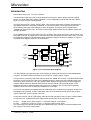
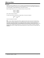
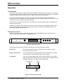
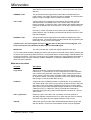
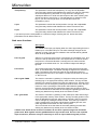
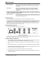
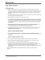
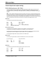
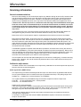
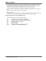
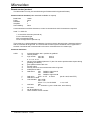
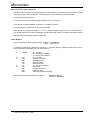
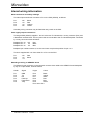
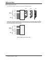
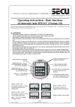
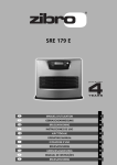
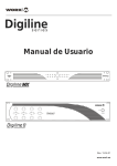
Microvideo
FLGS-1 & 2
SDV Flash logo generator
user manual
Contents
Introduction
..................................................... 3
FLG product specification
.......................................... 5
Inputs - SDV . . . . . . . . . . . . . . . . . . . . . . . . . . . . . . . . . . . . . . . . . . . . . . . . . . .
Inputs - Control . . . . . . . . . . . . . . . . . . . . . . . . . . . . . . . . . . . . . . . . . . . . . . . . .
Outputs - SDV . . . . . . . . . . . . . . . . . . . . . . . . . . . . . . . . . . . . . . . . . . . . . . . . . .
Outputs - Control . . . . . . . . . . . . . . . . . . . . . . . . . . . . . . . . . . . . . . . . . . . . . . . .
Installation
5
5
5
5
...................................................... 6
Unpacking and Inspection . . . . . . . . . . . . . . . . . . . . . . . . . . . . . . . . . . . . . . . . . .
Physical siting requirements . . . . . . . . . . . . . . . . . . . . . . . . . . . . . . . . . . . . . . . .
Environmental . . . . . . . . . . . . . . . . . . . . . . . . . . . . . . . . . . . . . . . . . . . . . . . . . .
Cooling Fans . . . . . . . . . . . . . . . . . . . . . . . . . . . . . . . . . . . . . . . . . . . . . . . . . . .
Electrical . . . . . . . . . . . . . . . . . . . . . . . . . . . . . . . . . . . . . . . . . . . . . . . . . . . . . .
6
6
6
6
7
Operation
....................................................... 8
Unit operation . . . . . . . . . . . . . . . . . . . . . . . . . . . . . . . . . . . . . . . . . . . . . . . . . . 8
Front panel controls . . . . . . . . . . . . . . . . . . . . . . . . . . . . . . . . . . . . . . . . . . . . . . 8
Main menu functions . . . . . . . . . . . . . . . . . . . . . . . . . . . . . . . . . . . . . . . . . . . . . 9
Grab menu functions . . . . . . . . . . . . . . . . . . . . . . . . . . . . . . . . . . . . . . . . . . . . 10
Preview functions . . . . . . . . . . . . . . . . . . . . . . . . . . . . . . . . . . . . . . . . . . . . . . . 11
FLG rear panel connections . . . . . . . . . . . . . . . . . . . . . . . . . . . . . . . . . . . . . . . 11
Troubleshooting FLG operation . . . . . . . . . . . . . . . . . . . . . . . . . . . . . . . . . . . . . 11
Logo “grab” process
. . . . . . . . . . . . . . . . . . . . . . . . . . . . . . . . . . . . . . . . . . . . . 12
How to grab a logo . . . . . . . . . . . . . . . . . . . . . . . . . . . . . . . . . . . . . . . . . . . . . . 12
Control input and output wiring
. . . . . . . . . . . . . . . . . . . . . . . . . . . . . . . . . . . . . 13
. . . . . . . . . . . . . . . . . . . . . . . . . . . . 13
RS232 / RS422 serial ports + GPI / TALLY
Servicing information
. . . . . . . . . . . . . . . . . . . . . . . . . . . . . . . . . . . . . . . . . . . . 14
General recommendations . . . . . . . . . . . . . . . . . . . . . . . . . . . . . . . . . . . . . . . . 14
Calibration adjustments . . . . . . . . . . . . . . . . . . . . . . . . . . . . . . . . . . . . . . . . . . 14
Remote control protocol . . . . . . . . . . . . . . . . . . . . . . . . . . . . . . . . . . . . . . . . . . 16
Internal wiring information
. . . . . . . . . . . . . . . . . . . . . . . . . . . . . . . . . . . . . . . . 18
Doc No:28
Doc Ref:FLGman21a.lwp
FLG user manual
Author:RLH Version:2 14/2/02
Page 1
Microvideo
Illustrations
Figure 1: FLG functional block diagram
................................ 3
........................................... 6
Figure 3: FLG Front panel
........................................... 8
Figure 4: FLG Front panel LCD
....................................... 8
Figure 5: FLG Rear panel
. . . . . . . . . . . . . . . . . . . . . . . . . . . . . . . . . . . . . . . . . . . 11
Figure 6: Mains input selection links
. . . . . . . . . . . . . . . . . . . . . . . . . . . . . . . . . . 19
Figure 2: Airflow diagram
FLG user manual
Author:RLH Version:2 14/2/02
Page 2
Microvideo
Introduction
Microvideo product code – FLGS-1 & FLGS-2.
The Microvideo Flash Logo Gen (FLG) is designed to put logos or station idents onto the outgoing
picture in a serial digital video (SDV) installation. It is an integrated logo generator and down stream
keyer in a single 1U rack mounting frame.
The logos are stored in a “Flash” memory store. This can be programmed 'in-system' and retains the
logo graphic data when the power is switched off. The memory store can be reprogrammed many
times, allowing the logos to be changed as often as required. The logos can be programmed or
“grabbed” through an SDV input. This allows a direct high quality transfer from a graphics system into
the logo generator.
Up to 8 different logos (including matte / key) can be held in each store, the FLGS-1 has one store, and
the FLGS-2 has two. The logos can be full colour and have transparent elements within them. From the
front panel the strage may be allocated to allow a full frame image to be stored in addition to logos. A
functional block diagram of the FLG is shown below:
LOOP
OUTPUT
POWER
FAIL
RELAY
BYPASS
SDV
INPUT
BACKGROUND
CPU
CONTROL
LOGO STORE
1
KEYER
MIXER
+
MATTE/KEY
INPUT
GRABBER
FOREGROUND
INPUT
LOGO STORE
2
PGM
OUTPUT
FADE TO
BLACK
AUX
DRIVER
KEYER
AUX
OUTPUT
(FLGS-2 only)
LOGO
PREVIEW
SWITCH
LOGO
PREVIEW
OUTPUT
GRAB
PREVIEW
OUTPUT
Figure 1: FLG functional block diagram
It is also possible to program the logos via an RS232 (or RS422) serial port from a standard desktop
computer. This feature allows both back-up and access to a large number of logos.
The FLG has two preview (PVW) SDV outputs, these are “GRAB” and “LOGO”. The GRAB PVW output
shows the source logo which is about to be grabbed, and the LOGO PVW output displays logos from
the memory store (or stores). The Logo preview output displays the logo keyed over the background
program feed to show how the final result will look, and the vertical and horizontal position of the
displayed logo can be adjusted before being put on air. In addition, later versions of the operating
software include a function to adjust the transparency of the logo.
The FLG is transparent to embedded audio and VBI data, which is passed to the program output from
the background input feed. A power fail bypass relay connects the background input to the program
output in the event of loss of power to the unit.
Front panel controls, with an LCD display, allow direct local operation of the FLG but it is also possible
to control the unit via RS232/422 from a Microvideo remote panel or an automation system.
FLG-S1
Single store, 8 logos,4 logos + 1 full frame image or 2 full frames
FLG-S2
Dual store, 8 logos or 4 logos + 1 full frame image in each store
The second logo store allows the storage of an additional 8 logos, and they can be downloaded even
with a logo on air (from the other store).
FLG user manual
Author:RLH Version:2 14/2/02
Page 3
Microvideo
FLG product specification
Inputs - SDV
Program SDV (BACKGROUND IN)
Serial SDV to SMPTE 259M, EBU Tech. 3267-E (270Mbit digital component)
Automatic cable equalisation for up to 250M of cable
Grab foreground SDV input (GRAB FGND IN)
Serial SDV to SMPTE 259M, EBU Tech. 3267-E (270Mbit digital component)
Grab matte SDV input (GRAB MATTE IN)
Serial SDV to SMPTE 259M, EBU Tech. 3267-E (270Mbit digital component)
3 X rear panel mounted BNC connectors
Inputs - Control
Logo fade up & logo fade down, held high on card at +5V
Provided on frame mounted (9 way D type socket) connector
Outputs - SDV
Program SDV output (PROGRAM OUTPUT)
(with power fail bypass from input)
Active loop through SDV output (LOOP OUT)
Program auxiliary SDV output (AUX)
Grab preview SDV output (GRAB PVW OUT)
Logo preview SDV output (PVW OUT)
Reclocked to EBU Tech 3267-E SMPTE 259M
5 X rear panel mounted BNC connectors
Outputs - Control
1 X Tally output, open collector, indicates logo on air.
Provided on frame mounted (9 way D type socket) connector
1 X RS232 (or RS422)
1 X RS422
Provided on frame mounted (9 way D type socket) connectors
FLG user manual
Author:RLH Version:2 14/2/02
Page 4
Microvideo
Installation
Unpacking and Inspection
Remove the supplied unit from its packing and examine it carefully, report any transit damage to the
shipping company and your local supplier, or Microvideo directly, as soon as possible.
Physical siting requirements
Mounting:
Standard 483mm (19-inch) rack bay with frame secured by four fixing screws
through the front panel fixing lugs. It is recommended that the rear of the frame is
supported to prevent any damage occurring to the fixing lugs themselves.
Vertical space:
44mm – 1U
No ventilation space is required above or below the frame.
Rear space:
The overall depth of the frame is 420 mm with at least an extra 20mm depth for the
rear panel connectors. Therefore, adequate space should be allowed behind the
frame for connections to be made without imposing strain on either cables or
connectors.
Weight:
7.5Kgs
Environmental
There are no special environmental requirements, but the normal precautions applicable to the siting of
electronic equipment should be observed. In particular, ensure that the ambient temperature is
maintained within the rated limits of 0°C to 25°C at a relative humidity not exceeding 90%
non-condensing.
Cooling Fans
The cooling fan inlet must not be obstructed in any way, as well as any warm air exhaust ports found on
the side of the unit. It is recommended that this unit is installed with equipment that has the same
airflow direction, to help prevent warm air being sucked into the fan inlet.
The airflow direction is illustrated below:
Rear of unit
Air in
Internal fan
Air flow direction
Warm air out
Exhaust vents
Front of unit
Figure 2: Airflow diagram
FLG user manual
Author:RLH Version:2 14/2/02
Page 5
Microvideo
Electrical
Before any power is applied to the unit, it is strongly recommended that the voltage label found on the
rear panel is checked to ensure the unit has been supplied for the correct local voltage. Please advise
your local supplier, or Microvideo directly, if this value is incorrect.
Mains voltage selection is by way of internal wire links, and may be set to:
240V a.c. 50/60Hz
220V a.c. 50/60Hz
110V a.c. 50/60Hz
(See: Internal wiring information)
The IEC mains socket is fitted with an integral 20mm (T) fuse and is rated at :
500mA - 240 / 220V
1A
- 110V
Power consumption is 60 watts.
! In order to obtain the best performance in regard to immunity from mains borne transients and
radio frequency emission interference, it is essential that the unit case is bonded to a protective earth.
The case is connected internally to the incoming mains earth, however it is recommended that an
additional protective earth strap is connected between the earth terminal provided on the rear of the unit
casework and a suitable external earth point. This may be the rack enclosure housing the equipment
itself but only if that too is suitably earth bonded, alternatively an earth strip may be provided within the
installation.
FLG user manual
Author:RLH Version:2 14/2/02
Page 6
Microvideo
Operation
Unit operation
The FLGS-1 stores logos in a flash memory store capable of handling a total of 8 logos, or 4 logos plus
1 full frame image, with the FLGS-2 having a similar capacity second store. Some versions of operating
software include a 2 full frame image mode, in addition to the above configurations.
The logo preview output displays any logo or image from a store unless a logo from that store is
currently on air. With no logo on air, the logo preview output will change as logos are selected, but once
a logo is put on air no further previewing is possible.
However, with an FLGS-2 logo generator, it is possible to continue to preview logos and images from
the off air memory store.
Therefore, if a logo is to be changed, the current on air logo will need to be faded down (taken off air)
prior to the previewing of the next logo. During the preview, the logo can have parameters such as
positioning changed before going on air.
Front panel controls
The FLG front panel is fitted with an alphanumeric Liquid Crystal Display (LCD), several selection
buttons and a rotary shaft encoder, as illustrated below:
Microvideo
Logo select
CAL=fade
INPUT
0
ON AIR
ENABLE CAL
BYPASS
SERIAL DIGITAL LOGO GENERATOR
10 BIT 4:2:2
Figure 3: FLG Front panel
The functions of the controls, indicators and display on the front panel are as follows:
Power LED
This LED indicates that power is applied to the unit, and the +5V rail
from the power supply is valid.
Rotary shaft encoder
A control that allows the variable parameter associated with the currently
selected function to be adjusted through its value range.
LCD display
A two line LCD that displays the currently selected function, the variable
parameter associated with that function, and any status messages such as
“BYPASS & ON AIR”. The display is illustrated below:
Currently selected
function
Logo select
CAL=fade
Variable
parameter
0
ON AIR
Status
indication
Figure 4: FLG Front panel LCD
FLG user manual
Author:RLH Version:2 14/2/02
Page 7
Microvideo
UP and DOWN
Two push buttons that allow access to all the FLG functions. Pressing
either button will move to the next function in the function list in the chosen
direction.
ENABLE + LED
This push button has a toggle action that enables or disables the front
panel controls. The LED is lit when the panel is enabled. The LCD will also
display a status message when this button is activated.
CAL + LED
A push button that if pressed once momentarily will reset the currently
selected function to its default value. The LED is lit each time the CAL
button is pressed, or when the rotary control adjusts the variable parameter
to display the default value for that function, for all other values it remains
unlit.
However, in certain functions the CAL button has a modified action. In
those instances, the LCD display will indicate what function the CAL button
has been assigned.
BYPASS + LED
This push button has a toggle action that enables or disables the active
bypass function. The active bypass provides a simple way of bypassing the
processing circuitry of the unit if required.
!! Please note: The active bypass function is not the same as the power fail relay bypass, as it
doesn't operate the relay between the SDV input and the PGM output.
INPUT LED
This LED indicates that a valid SDV signal is present at the input.
The FLG front panel defaults to display the main menu functions in the order shown below. Pressing the
UP button will cycle through these functions in a sequential fashion, and pressing the DOWN button will
reverse this sequence. The rotary control can then be used to adjust any of the displayed parameters. If
the display shows the status message “PANEL DISABLED”, pressing the ENABLE button once will
allow front panel operation.
Main menu functions
Function
Description
Logo select
Allows the selection of logos and images from the store, logos are
numbered 0 - 7. However if the FLG is configured for full frame operation,
(see: Frame mode) logos are numbered 0 - 3 with 4 being the full frame
image. Pressing the CAL button will initiate a fade of the selected logo to
air. A letter F shown in the lower right hand corner of the display indicates
that the logo is currently faded down (off air).
Fadetime
A logo fade can be initiated by either an external GPI, or by pressing the
CAL button while in this menu (or logo select). A letter F shown in the lower
right hand corner of the display indicates that the logo is currently faded
down (off air), and a status message displays whether the next fade will be
a fade IN (on air), or a fade OUT (off air).The fade time parameter is
adjustable using the rotary shaft encoder between the values of 1 and 99
video frames.
CAL > grab menu
Enters the “grab” menu when CAL is pressed. On some versions of
operating software a fade down will occur when the grab menu is entered
to ensure a logo grab does not happen whilst the store is on air.
625/525
Selects the input and output video standard between 625 line (PAL) and
525 line (NTSC). On this menu the software revision may be displayed.
FLG user manual
Author:RLH Version:2 14/2/02
Page 8
Microvideo
Transparency
This parameter controls the transparency of a logo and is adjustable
using the rotary shaft encoder between the values of 0 and 512 (full scale).
Once the transparency parameter of a logo has been changed, any
subsequent fades on or off air are with respect to this value. Pessing CAL
will set the value to 512 ie fully on. The transparency is stored for each
logo. If you can’t see a logo when it is ON AIR then check the
transparency value.
V pos
This parameter controls the vertical position of a logo and is adjustable
using the rotary shaft encoder between the values of 240 and -600.
H pos
This parameter controls the vertical position of a logo and is adjustable
using the rotary shaft encoder between the values of 240 and -600.
V pos and H pos are not adjustable on a full frame image. Pressing the CAL button sets these
parameters to their default value of 0.
Grab menu functions
Function
Description
Grab pvw
The GRAB PVW output can display either the video signal being fed to the
FGND input, or the MATTE input. The status message changes as the
selection is made. This output is masked to the area that will be grabbed
which is set by GRAB POS.
Posn to grab
Selects 1 of 4 sectors of the picture. The sectors are numbered 0 to 3, and
sector 0 is the top left hand corner. The sequence then continues around
the picture in a clockwise direction. Pressing the CAL button sets this
parameter to its default value of 0. For full frame images this setting is
ignored.
Pvw source
The LOGO PVW output can display either the video signal from the logo
store, or the GRAB input. The status message changes as the selection is
made. This feature overcomes the need for two separate monitors to
display the PVW sources, or the need to re-cable connections on the rear
of the FLG unit.
CAL to grab FGND
This function controls the “grabbing” of foreground video and storing the
resulting logo in an appropriate memory store location. The logo number
(position in the store) is retained from the logo select menu, however if this
is incorrect it can be changed by rotating the shaft encoder. Once the logo
number is correct, pressing the CAL button will initiate the grabbing
process, and foreground logo data will be written into the memory store.
The LCD will then show the status of the foreground grabbing process after
erasing any data that may already be in the chosen location.
CAL - grab matte
This function controls the “grabbing” of the matte input video and storing it
in the appropriate memory store location. The logo number (position in the
store) is retained from the logo select menu, however if this is incorrect it
can be changed by rotating the shaft encoder. Once the logo number is
correct, pressing the CAL button will initiate the grabbing process, and
matte logo data will be written into the memory store.
The LCD will then show the status of the matte grabbing process after
erasing any data that may already be in the chosen location.
!!Please note: Some earlier versions of software do not have separate foreground and matte
grab menus. Both signals must be grabbed before a logo can be used. There are two separate
input connectors, therefore it may be necessary to move an input cable during this process.
FLG user manual
Author:RLH Version:2 14/2/02
Page 9
Microvideo
CAL = erase logo
This function allows the erasure of a selected logo. The process involves
writing black to the appropriate matte memory position. This makes the
logo invisible.
Frame mode
This function configures the FLG memory store for either 8 logos, or 4
logos plus 1 full frame image. However, some versions of operating
software include a 2 full frame image mode, in addition to the above
configurations.
!!Please note: Normally the full frame image doesn't use a matte, as this mode is intended for
images such as apology captions. An additional hardware option is available if a full frame matte
is required, please discuss with Microvideo.
CAL > main menu
Pressing the CAL button will return the FLG to the main menu display. As
the FLG was faded down when the grab menu was entered, a fade up will
be required to put any logo on air.
Preview functions
The FLG is fitted with two preview outputs, and these are controlled by menu options.
The LOGO PVW will switch between the logo store output (via a keyer), and the foreground grab input.
It cannot preview the matte input. Therefore, during the grabbing process it is advisable to use the
GRAB PVW as this can be switched between the foreground and the matte inputs. However, once the
grab process has been completed the monitor can be connected back to the LOGO PVW. This may
involve moving a cable from one connector to another.
FLG rear panel connections
The FLG rear panel SDV connections are shown below:
PVW OUT
BACKGROUND IN
LOOP OUT
PROGRAM OUT
GRAB PVW OUT
AUX OUT
270Mb/s
SERIAL
GRAB MATTE IN
GRAB FGND IN
Microvideo
SERIAL DIGITAL
LOGO GENERATOR
10bit 4:2:2
Figure 5: FLG Rear panel
In addition to the above SDV connection, there are two serial ports (RS232 & RS422) mounted on the
rear of the FLG chassis, adjacent to the IEC mains input connector.
Troubleshooting FLG operation
1. If a logo has been grabbed and doesn't appear on the LOGO PVW, check both the horizontal and
vertical positioning, as well as the transparency parameters (max 512 - full on).
2. If picture appears to be unstable (or unlocked), check the video standard setting is correct, 625 or
525.
3. The LED labelled “INPUT” on the front panel is lit when a valid background SDV signal is applied.
4. Check the transmission path through the FLG by operating the power fail bypass function, i.e. Turn
off the unit and check the SDV signal at the output.
5. A valid logo requires both the foreground and matte sources to be grabbed.
6. The software version is displayed on the LCD after power is applied. It also appears on the video
standard menu display.
FLG user manual
Author:RLH Version:2 14/2/02
Page 10
Microvideo
Logo “grab” process
How to grab a logo
The following is an example procedure of grabbing a logo via the FGND and MATTE SDV inputs:
1. Ensure that the logo source is connected, i.e. the MATTE IN is connected to the matte source of the
logo and that FGND IN is connected to the foreground source of the logo. If the software version
provides for separate foreground and matte grabs then both connections are not required at the
same time.
2. Go into the “Logo Select” menu and select the position the new logo is to be stored in, this will avoid
any existing logos being accidentally erased.
3. Enter the grab menu by using the “CAL > grab menu” function.
4. Connect a monitor to the GRAB PVW output. A partially shaded screen will be seen, with a window
cut out and the source logo should be observed through the window. If not, enter the “Posn to grab”
menu, and by turning the shaft encoder, the window can be moved until the logo is observed. There
are 4 positions to choose from. A grab of a full frame image ignores the position setting and grabs
the whole frame.
5. Ensure that both the video and matte sources are correct. To do this, enter the “Grab pvw'” menu,
and toggle between video and matte using the shaft encoder, both should be observed.
On a non-transparent logo, the matte will appear as a white graphic block.
6. Once satisfied with the new logo, enter the “CAL to grab FGND” menu.On entering this menu, the
shaft encoder can select between logos 0-7, ensure the correct logo number to overwrite is
selected, then press CAL to grab.
The following should be observed on the LCD:
Erasing...... Pic:line (a count from 1 to 256).
7. To now grab the matte, enter the “CAL - grab matte” menu. On entering this menu, the shaft
encoder can select between logos 0 - 7, ensure the correct logo to overwrite is selected, then press
CAL to grab.
The following should be observed on the LCD:
Erasing...... Matte:line (a count from 1 to 256).
8. When this is procedure is finished, the logo will have been saved to the chosen location.
9. Return to the main menu and fade the logo in. To exit the “grab menu” and re-enter the “Main
menu”, go to the “CAL > main menu” function and press CAL.
10. The new logo will now be available for preview from the LOGO PVW output and it may be
necessary to move a cable to connect the monitor to this output. Adjust “H pos” and “V pos” until
the logo can be seen, and is correctly positioned. Any changes that are required to the
transparency can also be made at this time, however if the logo is not satisfactory, repeat the above
grab procedure.
A message ERASE ERROR or PGM ERROR indicates a hardware fault, call Microvideo for
assistance.
FLG user manual
Author:RLH Version:2 14/2/02
Page 11
Microvideo
Control input and output wiring
RS232 / RS422 serial ports + GPI / TALLY
The FLG is fitted with both an RS232 and an RS422 serial port to allow remote control from a PC,
automation system, or a Microvideo remote control panel. In addition, the RS232 port provides
connections for the GPI and Tally control signals. Both of the serial ports are standard 9 way D type
sockets.
! In order to obtain the best performance with regard to immunity from mains transients and radio
frequency interference it is essential that the remote cable is screened and fitted with a shielded hood.
The cable screen should connect to the shielded hood, and therefore to the chassis of the FLG unit,
however the screen should remain unconnected at the controller (PC, etc.) end. Do not connect pins 5
and 9 of the RS232 port unless they are required to avoid false GPI triggering due to noise.
RS232 port
The RS232 port provides the following signals:
Pin 1
Pin 2
Pin 3
Pin 4
Pin 5
RX
Pin 6
TX
Pin 7
GND
Pin 8
GND
Pin 9
Fade Down (GPI input)
Tally out
n/c
GND
Fade Up (GPI input)
GPI and TALLY signals
A Fade Down can be initiated by a taking Pin 5 low (GND), in a momentary action.
A Fade Up can be initiated by a taking Pin 9 low (GND), in a momentary action.
The Tally output is provided on Pin 6, this is an open collector TTL output (unprotected), therefore
damage may occur is the voltage on this pin exceeds +12V or goes below 0V.
The Tally signal is high when a logo is present on the PGM output.
RS232 cable
The wiring for a typical cable to connect the RS232 port to a PC is shown below:
FLG (9 way plug)
Pin 1
Pin 2
Pin 3
RX
TX
GND
PC (9 way socket)
to
to
to
Pin 3
Pin 2
Pin 5
Pin 4 to 6 (link)
Pin 7 to 8 (link)
RS422 port
The RS422 port provides the following signals, and is wired as a VTR:
Pin 1
Pin 2
Pin 3
Pin 4
Pin 5
GND
TXRX+
GND
n/c
FLG user manual
Author:RLH Version:2 14/2/02
Pin 6
Pin 7
Pin 8
Pin 9
GND
TX+
RXGND
Page 12
Microvideo
Servicing information
General recommendations
Due to its robust design, the FLG should not require any attention during its service life, however there
may be occasions where the top cover will need to be removed to gain access, and this will expose
dangerous voltages within the chassis. Therefore, any adjustment or upgrade work should only be
carried out by a qualified technician, as it may have to be carried out with power applied to the FLG.
!! Please note: The FLG top cover is connected to the frame by a short lead attached to the right
hand rear corner, this is connected directly to an internal earth terminal. In addition, the centre
screw fixings at the front (top & bottom), are shorter than all the other fixing screws. Therefore,
ensure these fixings are returned to their correct position, otherwise damage to the LCD panel
may result.
To remove the top cover, undo the mounting screws and lift off, ensuring that the earth lead is not
damaged during this procedure. Remove the earth lead from the top cover, if necessary.
Removal of an FLG circuit board for repair or replacement is from the front of the unit, as follows:
Disconnect the mains supply. At the front of the unit, remove the six screws holding the front panel
assembly to the case. The front panel connects to the GRABCPU board by a 40 way IDC cable. Take
care not to strain the cable when removing the front panel. The boards are fitted with ejectors. The
upper board is the GKEY board and the lower board is the GRABCPU board. Note that for servicing the
boards may be reversed so that there is access to either board when the lid is removed. The BNC
connections are then reversed.
If a Software Upgrade is required, follow the above procedure, and remove the 40 way IDC from the
lower board (GRABCPU). The lower board should now slide out (use the board ejector). Remove U14
using an extractor tool, and replace with new software EPROM. Ensure that it is fitted the correct way
round as indicated on the silk screen. Replace the board in the unit, replace cable and screws,
reconnect the unit and power up to check for correct operation.
The front panel can be removed without taking the FLG unit from the racking bay, or without removing
the top cover. However, the unit will need to be pulled out about 3 cm to allow access to the top and
bottom fixing screws.
Calibration adjustments
The latest versions of the FLG boards do not require any calibration for the serial inputs and outputs, as
Gennum devices are used throughout.
Clock regenerator (GKEY board)
The output timing is locked to the background SDV input. An Internal clock is generated and derived
from a crystal oscillator which is locked to the input by a phase locked loop. The pulling range of the
oscillator is +/- 100kHz from a centre frequency of 27.000MHz.
The crystal oscillator may be disabled using LK13 and the output then uses the input clock.
LK13 INT 1-2 use regenerated clock - normal position
LK13 EXT 2-3 use external clock
Setting up the clock regenerator:
If the clock regenerator is failing to lock properly then this will result in horizontal stripes running down
the picture. First check that the SDV LOOP OUT has no errors. Then move LK13 to position EXT. If
fault goes away then RV2 needs adjustment or input has wide jitter spectrum.
RV2 sets the relative phase of the input and output clocks when they are locked and should not
normally require adjustment.
To set RV2 an oscilloscope with at least 100MHz bandwidth is required. Connect two channels of
scope to TP9 and TP8.
FLG user manual
Author:RLH Version:2 14/2/02
Page 13
Microvideo
TP9 - Input clock TP8 - Internal clock TP7 - Ground.
Lock the scope to the 27MHz clock on TP9 with timebase of 20ns/ div. The two clocks should be
normally be in phase. Adjust RV2 such that the clocks are in phase. Check that there is no phase
difference between the scope probes by putting them both on the same test point.
On earlier version cards there is also adjustment for the oscillator free run frequency.
To set the oscillator centre frequency move link LK14 to position 1-2 and set CV1 for 27.000MHz on
TP9.
Link LK14 should normally be in position 2-3 (towards U21).
Mode control links:
Links LK17 & 18 should normally be 1-2, this enables 8 logo store. Position 2-3 enables 4 logos + full
frame image. These are normally factory set according to firmware and software fitted.
CPU card links and internal wiring (GRABCPU board)
CPU links are set at factory and should not be changed:
LK1
LK2
LK4
LK6
LK8
LK9
LK10
LK12
1-2 (away from 'LK1' on silk screen) for 32kB EPROM
1-2 (towards 'LK2' on silk screen) for 32kB RAM
2-3 (towards 'LK4' on silk screen) to enable battery backup
1-2 (towards R38) for Port 1 RS422
fitted for relay control
fitted for L/R control
2-3 (towards 'LK10' on silk screen) for V flag to VIA
1-2 (towards U21) to disable watchdog timer
FLG user manual
Author:RLH Version:2 14/2/02
Page 14
Microvideo
Remote control protocol
The Microvideo FLG may be controlled using an RS232 serial link (optional RS422).
Communications Standard (other standards available on request)
Baud Rate
Parity
Data Bits
Stop Bits
Hand shaking
19200
None
8
1
None
Communications use ASCII characters, to send a command six ASCII characters are required:
Send ”!” C PPP CR.
”!” is the ASCII character (decimal 33)
C is the Command type.
PPP is hexadecimal data.
CR is Carriage Return (decimal 13)
There must be no spaces between characters (just send 6 bytes), although other characters before or
after a command will be ignored. The FLG will wait for each byte so commands can be typed from a
terminal. Commands will not be echoed but for some commands there is a status reply.
Command definitions
ASCII
H
V
P
G
W
Y
Z
R
X
F
f
S
s
J
T
V
horizontal position 000 = position as grabbed
vertical position
logo number
000..007
store A
008..00F
store B
0..4 = A, 5..9 = B
set logo to be grabbed (same as 'P') but G is used to provide status reports during
grabbing (see below).
grab quadrant select 000..003
preview select
used by remote to set machine state value is ignored.
matte/picture select
fade select
000
BGND to logo store A
001
BGND to black
002
BGND to logo store B
fade value
PPP = 0..7FF 0= down
(but for 100% send FFF)
fade time in fields
Line standard 625 = 0PB
525 = 1PB
where P=0, B= BYPASS
1= on, 0=off
start fade
00P
P = direction e.g. 001= fade down, 000= fade up
Mix value
set all variables to cal
return software version number
FLG user manual
Author:RLH Version:2 14/2/02
Page 15
Microvideo
Reply from FLG - Status Response
The Microvideo FLG does not normally reply to a command but may output status information. A status
output is sent when the local panel is used so that any connected remote panel is updated.
The status packet has the form:
“%” X PPP CR LF, where CR is Carriage Return, and LF is Line Feed.
There will be no spaces between characters, i.e. there are 7 bytes.
Command type X and PPP are as same as commands.
When a fade is in progress a string of ++++ or ---- is issued depending on direction. This is ignored by
any remote panel but is useful for debugging and also flags that a start 's' command has been received.
The fade value is sent at the end of the transition.
Status Reports
The FLG regularly outputs the input status: %I000 = no BGND input
%IFFF = input present
To obtain the status at any time send command: ”?” C 000 CR. Reply is %EFEE if there was an error in
serial command. Command types are case sensitive.
Z
%ZMBA
X
G
00m
010
020
030
110
0xx
010
020
000
EEE
U
E
M = mix state
B = store B logo selected
A = store A logo selected
m = mix state
Erasing in progress
Grabbing picture
Grabbing matte
Grab successful
xx = line being grabbed
Erase error
Programming error
Serial port error
unknown command received
When a GPI input is activated the FLG sends:
FLG user manual
Author:RLH Version:2 14/2/02
%BFBB for fade up
%AFAA for fade down
Page 16
Microvideo
Internal wiring information
Mains transformer secondary windings
The mains input transformer connects to PL1 on the PSU (SPOW), as follows:
Pin 1
Pin 2
Pin 3
Pin 4
12V
0V
0V
12V
Black
Red
Orange
Yellow
Secondary wiring connector may be fitted either way round on the PSU.
Power supply output connections
The integral PSU (SPOW) supplies + and -5V to the two FLG boards via a 10 way connector (PL5) and
a distribution terminal block. The two power rails are connected to the FLG board backplane connectors
by a 3 way connector wired as follows:
Backplane Pin 10
Backplane Pin 11
Backplane Pin 12
+5V
0V
-5V
Red
Black
Blue
Backplane pin numbers start at 4, as the co-ax insert occupies the position for pin 1 to 3.
The fan is supplied with +5V from either PL7 or PL9 on the PSU.
Pin 1
Pin 2
Pin 3
+5V
0V
n/c
Red
Black
RS232 D type wiring to GENCPU board
The RS232 D type connector on the rear panel connects via a cable to the GENCPU board backplane
by way of a 6 pin header, wired as follows:
Header
Signal
D type
Pin 1
Pin 2
Pin 3
Pin 4
Pin 5
Pin 6
GND
TX
RX
Fade Up
Fade Down
Tally
Pin 3
Black
Pin 2
Yellow
Pin 1
White
Pin 5
Red
Pin 9
Blue
Pin 6
Green
Pin 4 link to Pin 3
FLG user manual
Author:RLH Version:2 14/2/02
Colour
Page 17
Microvideo
Mains voltage selection links
The mains input voltage is selected by internal links, as illustrated below:
240V
BLUE - 0
A2
A2
A2
B1
B2
B2
B2
C1
C2
C2
C2
WHITE - B0
D1
D2
D2
D2
PINK - B110
E1
E2
E2
E2
BROWN - B130
MAINS
INPUT
110V
A1
VIOLET - 110
PRIMARY
WINDINGS
220V
F1
F2
F2
F2
NEUTRAL
G1
G2
G2
G2
LIVE
H1
H2
H2
H2
EARTH
I1
I2
I2
I2
!!
Please note: The primary winding colours shown above are for the standard 60VA transformer
only, 90VA transformer primary windings are coloured differently (as shown below), however
the link configurations remain the same.
PRIMARY
WINDINGS
90VA
VIOLET - 0
A1
A2
PINK - 110
B1
B2
C1
C2
BLUE - B0
D1
D2
WHITE - B110
E1
E2
GREY - B130
MAINS
INPUT
F1
F2
NEUTRAL
G1
G2
LIVE
H1
H2
EARTH
I1
I2
Figure 6: Mains input selection links
FLG user manual
Author:RLH Version:2 14/2/02
Page 18