1
PRINTSERVER
Installation Manual
Names of companies and products mentioned in this manual are trademarks or
registered trademarks of their respective owners.
The manufacturer will not accept any liability for any error or omission. The
information in this manual is subject to change without notification.
All rights are reserved. Copying, other reproduction or translation without the
prior written consent from the manufacturer is prohibited.
Installation Manual release 2.0
Contents
Contents
CHAPTER 1
Network Know How............................................... 1-1
1.1 Basic Terminology..........................................................................................................1-2
1.1.1 Hardware address............................................................................................................................... 1-2
1.1.2 Print Server Name.............................................................................................................................. 1-3
1.1.3 Logical Printers .................................................................................................................................. 1-4
1.2 Basic TCP/IP Terminology.............................................................................................1-7
1.2.1 IP Address .......................................................................................................................................... 1-7
1.2.2 Methods of Saving the IP Address in the Print Server ...................................................................... 1-8
1.2.3 Host Name........................................................................................................................................ 1-13
1.2.4 ARP Table........................................................................................................................................ 1-14
1.2.5 TCP/IP Ports .................................................................................................................................... 1-15
1.2.6 Gateway ...........................................................................................................................................1-17
1.2.7 Subnet Mask..................................................................................................................................... 1-17
1.3 DHCP ............................................................................................................................1-19
1.4 Rendezvous / ZeroConf ................................................................................................1-21
1.5 SNMP............................................................................................................................1-23
CHAPTER 2
Installation in WLAN Networks.............................. 2-1
2.1 Basic Principles...............................................................................................................2-2
2.2 Installation for Use in the Ad-Hoc Mode .......................................................................2-4
2.3 Installation for Use with Unencrypted Access Points.....................................................2-5
2.4 Installation for Use with Protected Access Points ..........................................................2-6
2.5 Troubleshooting ..............................................................................................................2-8
2.5.1 Interpreting the Status Page ............................................................................................................... 2-8
2.5.2 Resetting Parameters.......................................................................................................................... 2-9
PRINTSERVER Installation Manual
i
Contents
CHAPTER 3
Installation in Windows Networks .......................... 3-1
3.1 Basic Principles ..............................................................................................................3-2
3.2 Installation in Windows Networks using the Printer Wizard ........................................3-3
3.3 Installing in Windows Networks using the PRINTSERVER Print Monitor (Encrypted
Printing) ................................................................................................................................3-5
3.3.1 Installing the PRINTSERVER Print Monitor.................................................................................... 3-5
3.3.2 Setting up the PRINTSERVER Print Monitor .................................................................................. 3-6
CHAPTER 4
Installation in Novell Networks .............................. 4-1
4.1 Basic Principles ..............................................................................................................4-2
4.2 Installing in NetWare 6/5/4 Networks in Print Server Mode .........................................4-5
4.2.1 Setting up a Print Server, Printer, and Print Queue ........................................................................... 4-5
4.2.2 Setting Up the Printer on the Computer............................................................................................. 4-6
4.3 Installing in NetWare 6/5 Networks in Print Server Mode (Pure IP).............................4-9
4.3.1 Setting up a Print Server, Printer and Print Queue .......................................................................... 4-10
4.3.2 Setting Up the Printer on the Computer........................................................................................... 4-12
4.4 Installing in NetWare 6/5/4 Networks in Remote Printer Mode ..................................4-15
4.4.1 Installing a print server, a printer, and a print queue ....................................................................... 4-16
4.4.2 Configuring the PRINTSERVER .................................................................................................... 4-19
4.4.3 Starting PSERVER on the File Server............................................................................................. 4-21
4.4.4 Setting Up the Printer on the Computer........................................................................................... 4-21
4.5 Installing in NetWare 6/5 Networks with NDPS Gateways.........................................4-23
4.5.1 Novell NDPS Gateway: lpr via IP ................................................................................................... 4-23
4.5.2 Novell NDPS Gateway: Remote Printer.......................................................................................... 4-30
4.5.3 Novell NDPS Gateway: Print Queue-Based.................................................................................... 4-40
4.5.4 Setting up the Printer in the Novell Printer Manager ...................................................................... 4-48
4.6 Tips and Tricks .............................................................................................................4-52
CHAPTER 5
Installation in UNIX Networks ................................ 5-1
5.1 Basic Principles ..............................................................................................................5-2
ii
PRINTSERVER Installation Manual
Contents
5.2 Assigning the IP Address to the Host Name...................................................................5-4
5.3 Saving the IP Address in the Print Server.......................................................................5-6
5.3.1 Saving the IP Address via BOOTP .................................................................................................... 5-6
5.3.2 Saving the IP Address via RARP....................................................................................................... 5-7
5.3.3 Saving the IP Address using the 'arp' and 'ping' Commands ............................................................. 5-8
5.4 Printing via the LPD Protocol.......................................................................................5-10
5.4.1 IBM AIX (Version 4.x).................................................................................................................... 5-11
5.4.2 IBM AIX (Version 3.x).................................................................................................................... 5-13
5.4.3 AIX Without SMIT.......................................................................................................................... 5-14
5.4.4 HP-UX (Version 10.20) ................................................................................................................... 5-16
5.4.5 SunOS .............................................................................................................................................. 5-18
5.4.6 SCO UNIX (Version 3.2)................................................................................................................. 5-19
5.4.7 UNIXWare (Version 4.2 - 1.1.2) .....................................................................................................5-20
5.4.8 System V (General).......................................................................................................................... 5-21
5.5 Printing via TCP/IP Ports..............................................................................................5-23
5.5.1 SINIX SPOOL V4.x/XPrint............................................................................................................. 5-23
5.6 Printing via Shell Scripts ..............................................................................................5-25
5.6.1 Creating the Print Server Directories ............................................................................................... 5-26
5.6.2 Integrating Shell Scripts into System V Systems............................................................................. 5-27
5.6.3 Integrating Shell Scripts into BSD Systems .................................................................................... 5-31
5.6.4 Integrating Shell Scripts into AIX Systems ..................................................................................... 5-35
CHAPTER 6
Installation in Apple Networks ............................... 6-1
6.1 Installation in Mac OS X Networks................................................................................6-2
6.1.1 Basic Principles.................................................................................................................................. 6-2
6.1.2 Installing the Print Server .................................................................................................................. 6-3
6.1.3 Configuring the Print Server .............................................................................................................. 6-6
6.2 Installation in Mac OS 9/8 Networks..............................................................................6-7
6.2.1 Basic Principles.................................................................................................................................. 6-7
6.2.2 Installing the PRINTSERVER........................................................................................................... 6-8
6.2.3 Installing the Virtual Printer .............................................................................................................. 6-9
6.2.4 Configuring the Print Server .............................................................................................................. 6-9
PRINTSERVER Installation Manual
iii
Contents
CHAPTER 7
Installation in AS/400 Networks............................. 7-1
7.1 Basic Principles ..............................................................................................................7-2
7.2 Creating a Remote Output Queue...................................................................................7-4
7.2.1 Saving the IP Address in the Print Server.......................................................................................... 7-4
7.2.2 Checking the IP Connection .............................................................................................................. 7-4
7.2.3 Creating a Remote Output Queue ...................................................................................................... 7-5
7.2.4 Starting the Remote Printer Writer .................................................................................................... 7-8
7.2.5 Troubleshooting ................................................................................................................................. 7-9
7.3 Creating a Device Description......................................................................................7-10
7.3.1 Saving the IP Address in the Print Server........................................................................................ 7-10
7.3.2 Checking the IP Connection ............................................................................................................ 7-10
7.3.3 Creating a Device Description ......................................................................................................... 7-11
7.3.4 Attaching the Device Description.................................................................................................... 7-17
7.3.5 Starting the Printer Writer................................................................................................................ 7-17
7.3.6 Troubleshooting ............................................................................................................................... 7-17
CHAPTER 8
Installation in BS2000 Networks............................ 8-1
8.1 Basic Principles ..............................................................................................................8-2
8.2 Saving the IP Address in the Print Server ......................................................................8-3
8.3 Installing a Print Server for TCP/IP ...............................................................................8-4
8.4 Entering the IP Address ..................................................................................................8-5
8.5 Installing the Print Server in the RSO Spooler...............................................................8-6
8.6 Defining the TCP/IP Port ...............................................................................................8-7
REFERENCE A
Shell Scripts ......................................................... A-1
A.1 Basic Principles ............................................................................................................ A-1
A.2 Function of Shell Scripts .............................................................................................. A-2
A.3 Description of Variables ............................................................................................... A-4
iv
PRINTSERVER Installation Manual
CHAPTER 1
Network Know How
This chapter contains information
concerning the following topics:
Basic Terminology
Basic TCP/IP Terminology
DHCP
Rendezvous / ZeroConf
SNMP
Know How
Print Server Installation Manual
1-1
Basic Terminology
1.1
Basic Terminology
In order to install your print server, you will need various data and
parameters. This information will be explained in this section.
1.1.1
Hardware address
Hardware Address
Structure
A print server is addressable by means of its world-wide unique
hardware address. This address is commonly referred to as the
MAC or Ethernet address. The manufacturer has defined this
address in the hardware of the print server. The address consists of
12 hexadecimal numbers. The first six numbers represent the
manufacturer, while the last six numbers represent the individual
card.
Where Can I Find
the Hardware
Address?
The hardware address of your print server is on a label pasted onto
the actual card or the box or pocket print server housing and can be
read easily.
On the print server, you will find a hardware address of
'00c0eb0001ff.' Here, '00c0eb' identifies the manufacturer, while
'0001ff' is the number of your print server. If your print server has
already been installed, you can find the hardware address using
either the print server homepage, the PRINTSERVER-NetTool,
SNMP, or the status page.
1-2
Print Server Installation Manual
Basic Terminology
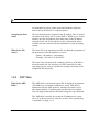
Spelling of the
Hardware Address
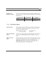
You must enter the hardware address during the installation of the
print server software. This entry varies depending on the operating
system in use:
Operating system
1.1.2
Representation
Example
Windows
Hyphens
00-c0-eb-00-01-ff
UNIX
Colons or periods
00:c0:eb:00:01:ff or
00.c0.eb.00.01.ff
Print Server Name
Name Structure
The print server name is made up of two letters 'IC' and the print
server number. The print server number consists of the last six
numbers of its hardware address.
Example:Hardware address:
Print server name:
00:c0:eb:00:01:ff
IC0001FF
Where Do I Find the
Name?
The print server name can also be found using either the print server
homepage, the PRINTSERVER-NetTool, SNMP, or the status
page.
Apple and Novell
Name
In Novell and Apple networks, the Novell orApple name is used.
Upon delivery, the print server name corresponds to the Novell or
Apple name. By means of the print server homepage, the
PRINTSERVER-NetTool, or parameter transfer via FTP, it is
possible to change the Novell or Apple name.
Print Server Installation Manual
1-3
Basic Terminology
1.1.3
Logical Printers
What Are Logical
Printers?
Logical printers are so-called pre-installed print server filters. Print
data is interpreted according to the set logical printer. The print
server has eight available logical printers. Each logical printer has
a different function.
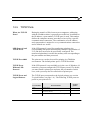
Which Logical
Printers Are
Available?
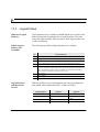
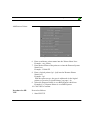
The following pre-defined logical printers are available:
No.
Logical Printers
with Box Print
Servers
Preset function
1
Default setting
2
Changes Line Feed (LF) to Carriage Return with Line Feed (LF+CR)
3
Converts ASCII data into PostScript data
4
Prints a banner page in Novell networks or if the LPD protocol is used
5
Prints all data in hex dump mode. Hex dump mode is mainly used to search for
errors in print data. The data is printed as a byte in hexadecimal form instead of
letters and numbers. Printer control commands are printed as hexadecimal
values and do not influence the printout in any way.
6
Not assigned
7
Not assigned
8
Supports the RSO Spooler (BS2000)
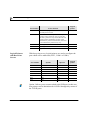
With box print servers, logical printers are used to configure the
port which will be addressed (LPT1, COM1 or USB1):
Logical printer
1-4
Option 1
Option 2
1
LPT1
LPT1
2
LPT2
USB1
3
LPT3
USB2
4
COM1
USB3
Print Server Installation Manual
Basic Terminology
Logical printer
Option 1
Option 2
5
LPT1
USB4
6
LPT1
LPT1
7
LPT1
LPT1
8
LPT1
LPT1
Option 2 allows you to connect a hub to the USB port. In this case,
four printers can be administered via USB 1 through 4 by means of
the logical printers.
Logical Printer
Configuration
You may change the function for every logical printer by changing
the corresponding configuration parameter. These parameters can
be configured using either the print server homepage, the
PRINTSERVER-NetTool, SNMP, or the FTP parameter transfer.
Addressing Logical
Printers
Depending on your system, logical printers may be addressed in
various ways.
Windows
In Windows networks, you may use the corresponding TCP/IP
ports instead of the logical printers. For more information, please
read the section "TCP/IP Ports" on page 1-15.
Novell
In Novell networks, the logical printers are addressed with '#1'
through '#8'.
UNIX
In UNIX networks, the logical printers are addressed with 'lp1'
through 'lp8'.
FTP
In the case of an FTP print data transfer, the logical printers are
addressed with 'lp1' through 'lp8'.
Example: put <file name> lp1
Print Server Installation Manual
1-5
Basic Terminology
Mac OS
1-6
In Mac OS X networks, the logical printers are addressed with lp1
through lp8. No logical printers are available in Mac OS 9/8
networks.
Print Server Installation Manual
Basic TCP/IP Terminology
1.2
Basic TCP/IP Terminology
In Windows and UNIX networks, TCP/IP is used for
communication between the various participants. In order to
install your print server in TCP/IP-based networks, you must enter
certain data and parameters. This information is described in the
following section. If you are already familiar with TCP/IP, please
read the "Installation in Windows Networks" chapter on page 3-1
or the "Installation in UNIX Networks" chapter on page 5-1.
1.2.1
IP Address
What is an IP
Address?
The IP address is the unique address of each node in a network, i.e.
an IP address may occur only once on a local network. The system
administrator usually assigns the IP address. The address must be
saved in the print server to make sure that it can be addressed
within the network. In this Installation Manual, the IP address
'192.168.0.123' is consistently used as an example.
IP Address Structure
IP addresses always consist of four address groups. Each group is
separated from the next group by a period. Every IP address is
divided up into the network ID and the user ID. This division is
primarily determined by the network class.
Print Server Installation Manual
1-7
Basic TCP/IP Terminology
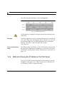
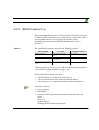
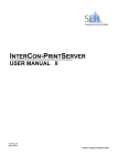
The following network classes can be distinguished:
Fig. 1-1: TCP/IP network classes
All IP addresses assigned in a logical network must belong to the
same class.
Example
You have applied for a class C network ID and receive network ID
'192.168.0.' Due to the fact that user IDs '0' and '255' are reserved
for broadcast addresses, a valid IP address must lie somewhere
between '192.168.0.1' and '192.168.0.254', such as
'192.168.0.123.'
ZeroConf IP address
range
The address range 169.254.0.1 to 169.254.255.254 is reserved for
the automatic assignment of IP addresses via ZeroConf. For more
information, please read the section "Rendezvous / ZeroConf" on
page 1-21.
1.2.2
Methods of Saving the IP Address in the Print Server
If you use TCP/IP as network protocol, you first have to save the
IP address in the print server. This is irrespective of whether you
use Windows, UNIX, or Apple networks.
1-8
Print Server Installation Manual
Basic TCP/IP Terminology
Once the print server is connected to the network and switched on,
the print server checks whether an IP address can be obtained from
a DHCP server or boot protocols. If this is not the case, the print
server assigns itself an IP address via ZeroConf. This IP address is
taken from the address range 169.254.0.1 to 169.254.255.254
which is reserved for ZeroConf.
In many cases, the print server is to be integrated into the actual
network after the automatic configuration via ZeroConf in the
169.254.x.x segment. To this end, a different IP address must be
saved in the print server. In this Installation Manual, the
PRINTSERVER-NetTool is always used for saving the IP address.
The following possibilities for saving the IP address are available:
DHCP
The BOOTP Boot Protocol
The RARP Boot Protocol
The arp and ping Commands
PRINTSERVER-NetTool
1.2.2.1
The BOOTP Boot Protocol
If your network uses the boot protocol BOOTP, the '/etc/bootptab'
file must be added. This file is located on the host running the
BOOTP daemon. The '/etc/bootptab' file contains a permanent
copy of the assignment of the host name and the IP address to the
hardware address.
Make sure that:
Print Server Installation Manual
1-9
Basic TCP/IP Terminology
9
The 'BOOTP' parameter has been activated (see status page).
What Happens
When the Print
Server is Turned on?
Once the print server has been turned on, it asks the BOOTP for
the IP address and the host name. The answer of the BOOTP host
server, which contains the IP address, is sent as a data packet and
saved in the print server.
What Happens
When Printing?
During the installation of the print server, its host name is
displayed on the monitor of the computer intended for printing.
The computer finds the IP address of the print server by means of
either the local 'etc/hosts' file or the DNS host. The print data can
then be sent to this IP address.
You can also enter the IP address instead of the host name during
the print server installation. In this case, you can send print data
directly to the IP address.
1.2.2.2
The RARP Boot Protocol
If your network uses the RARP boot protocol, either the
'/etc/ethers' file or the '/etc/rarpd.cf' file must be added.
The choice of which file to add depends on how the RARP
network service was implemented on your UNIX system. For
more information, please read the section concerning 'rarpd' in
your UNIX documentation.
Both files are located on the host running the RARP daemon. The
files contain a permanent copy of the assignment of the host names
and the IP address to the hardware address.
Make sure that:
9
1-10
The 'RARP' parameter has been activated (see status page).
Print Server Installation Manual
Basic TCP/IP Terminology
What Happens
When the Print
Server is Turned on?
Once the print server has been turned on, it asks the RARP for the
IP address and the host name. The answer of the RARP host
server, which contains the IP address, is sent as a data packet and
saved in the print server.
What Happens
When Printing?
During the installation of the print server, its host name is
displayed on the monitor of the computer intended for printing.
The computer finds the IP address of the print server by means of
either the local 'etc/hosts' file or the DNS host. The print data can
then be sent to this IP address.
You can also enter the IP address instead of the host name during
the print server installation. In this case, you can send print data
directly to the IP address.
1.2.2.3
The arp and ping Commands
By means of the 'arp' and 'ping' commands, you can save the IP
address in the print server.
If the print server already has an IP address, the 'arp' and 'ping'
commands cannot be used to save a new IP address in the print
server. However, an IP address from the address range 169.254.0.1
to 169.254.255.254 which is reserved for ZeroConf can be
overwritten by means of the 'arp' and 'ping' commands.
Use the 'arp' and 'ping' commands to save the IP address if your
network has no superordinate management of IP addresses and
host names, such as a DNS or WINS server.
The 'arp' command is used for editing the ARP table. The 'ping'
command sends a data packet with an IP address to the hardware
address of the print server. If the data packet has been successfully
Print Server Installation Manual
1-11
Basic TCP/IP Terminology
sent and received, the print server permanently saves the IP
address.
The implementation of the 'arp' and 'ping' command depends on
the system used. For more information, please read the relevant
section in the documentation of your operating system.
Make sure that:
9
The 'ARP/PING' parameter has been activated (see status
page).
Proceed as follows:
1. Edit the ARP table:
Syntax: arp -s <IP address>
<hardware address>
Example: arp -s 192.168.0.123 00-c0-eb-00-01-ff
2. Assign a new IP address to the print server:
Syntax: ping <IP address>
Example: ping 192.168.0.123
Trouble Shooting
1.2.2.4
The 'Addition failed' error occurs when you use the 'arp'
command. This error informs you that the ARP table is empty and
that the new entry cannot be added. This problem occurs with
certain operating systems such as all Microsoft Windows versions
with the exception of NT 4.0. The solution to the problem is to
ping a station in the network before using the 'arp' command for
the first time or use the PRINTSERVER-NetTool to enter the IP
address.
PRINTSERVER-NetTool
You can easily enter the IP address and thus save it in the print
server using the PRINTSERVER-NetTool.
1-12
Print Server Installation Manual
Basic TCP/IP Terminology
Saving the IP address using the PRINTSERVER-NetTool in
networks with routers is only possible if the router forwards
multicast requests and the print servers are searched for via
multicast. For more information, please read the section
"Searching for Print Servers" on page 4-5 of the User Manual.
If the print server is connected and the printer is switched on, the
print server is displayed in the print server list under 'ZeroConf'
with an IP address from the address range 169.254.0.1 through
169.254.255.254, which is reserved for ZeroConf. The desired IP
address can be entered via the shortcut menu.
For more information concerning the PRINTSERVER-NetTool ,
please read the "PRINTSERVER-NetTool" chapter on page 4-1 in
the User Manual.
Proceed as follows:
1.
2.
3.
4.
5.
1.2.3
Call the PRINTSERVER-NetTool.
Right-click the 'New Print Server' in the print server list.
Select 'IP Wizard...' from the shortcut menu.
Select 'Manual TCP/IP configuration'.
Follow the instructions of the installation routine.
The IP address is saved in the print server.
Host Name
What Is a Host
Name?
Print Server Installation Manual
The host name is an alias for an IP address. We recommend that
you always use a host name. If the IP address changes, only the
file containing the assignment of the host name to the IP address
must be changed. The host name used to address the print sever in
your local network may be chosen freely. It is, however,
1-13
Basic TCP/IP Terminology
recommended to select a name associated with the respective
board, such as IC0001FF, or with the printer.
Assigning the Host
Name
The host name must be assigned to the IP address. This is carried
out either in the 'hosts' file or on the DNS or WINS server. In this
manual, only the assignment of the host name to the IP address
using the 'hosts' file is described. For more information, please
read the relevant section in the documentation of your operating
system.
What Is the File
'hosts'?
The 'hosts' file is an internal system file in which the assignment of
the host names to the IP addresses is saved.
Syntax: <IP address> <host name>
Example: 192.168.0.123 IC0001FF
The 'hosts' file is located in the 'windows' directory in Windows
networks and in the 'etc' directory in UNIX networks. In other
operating systems, such as AS/400 for example, the name of the
assignment file may differ.
1.2.4
ARP Table
What Is the ARP
Table?
The ARP table is an internal system file in which the assignment
of IP addresses to hardware addresses is saved. This table is
administered by the ARP protocol, whereby the entries expire
after approximately 15 minutes and can therefore be forgotten.
You can display and edit the ARP table using the 'arp' command.
The ARP table is needed for saving the IP addresses in a print
server if no boot protocol is used (see section "The arp and ping
Commands" on page 1-11).
1-14
Print Server Installation Manual
Basic TCP/IP Terminology
1.2.5
TCP/IP Ports
What Are TCP/IP
Ports?
During the transfer of files between two computers, addressing
with the IP address alone is generally not sufficient. In addition to
the IP address, a port number (TCP/IP port) is used. This number
defines the computer memory area that is reserved for a specific
communications connection. The combination of an IP address
and a port number is unique for every communications connection
and is defined as a socket.
LPD Protocol and
TCP/IP Ports
If the LPD protocol is used for transferring print data, the
corresponding data packet automatically contains a port number of
'515' and does not need to be specifically configured. The
transferred print data is saved to the memory area corresponding to
the port number and then processed.
TCP/IP Port 4000
The print server can also be used for printing in a ThinPrint
environment. The default printer port is TCP/IP Port 4000.
TCP/IP Ports
Without LPD
Protocol
If the LPD protocol is not available, as in the case of Windows 98
networks, you must configure the TCP/IP port yourself. To do this,
you must install a printer port and enter the port number. In this
case, such a port may also be called a direct printer port.
TCP/IP Ports and
Logical Printers
The TCP/IP port corresponds to the logical printers (see section
"Logical Printers" on page 1-4 ). The following TCP/IP ports are
preset in your print server:
Port number
Print Server Installation Manual
Logical
printer
Preset function
9100
Default setting
1
9101
Changes Line Feed (LF) to Carriage Return with
Line Feed (CR+LF)
2
9102
Converts all data from ASCII to PostScript
3
1-15
Basic TCP/IP Terminology
Port number
Logical Printers
with Box Print
Servers
Logical
printer
Preset function
9103
Prints a banner page in Novell networks or when
the LPD protocol is used
4
9104
Prints all data in hex dump mode. Hex dump mode 5
is mainly used to search for errors in print data.
The data is printed as a byte in hexadecimal form
instead of letters and numbers. Printer control
commands are printed as hexadecimal values and
do not influence the printout in any way.
9105
Not assigned
6
9106
Not assigned
7
2900
Supports the RSO Spooler (BS2000)
8
With box print servers, logical printers are used to configure the
port which will be addressed (LPT1, COM1 or USB1):
Port number
Option 1
Logical
printer
Option 2
9100
LPT1
LPT1
1
9101
LPT2
USB1
2
9102
LPT3
USB2
3
9103
COM1
USB3
4
9104
LPT1
USB4
5
9105
LPT1
LPT1
6
9106
LPT1
LPT1
7
2900
LPT1
LPT1
8
Option 2 allows you to connect a hub to the USB port. In this case,
four printers can be administered via USB 1 through 4 by means of
the TCP/IP ports.
1-16
Print Server Installation Manual
Basic TCP/IP Terminology
1.2.6
Gateway
Using a gateway, you can address IP addresses from external
networks. Your print server is configured not to use gateways by
default. If your network is not split into subnetworks, you do not
need to take any further steps. If, however, you are using a
gateway in your network, you should ask your system
administrator for the IP address of the gateway. These parameters
can be configured using either the print server homepage, the
PRINTSERVER-NetTool, SNMP, or the FTP parameter transfer.
If the parameter 'Multicast router as gateway' has been enabled,
the print server searches for a gateway independently. If the print
server finds a gateway, the IP address of that gateway is entered
automatically. If the gateway is not the right one, disable the
parameter and enter the IP address of the right gateway manually.
For more information, please read the section "Configuring
TCP/IP" on page 4-20 of the User Manual.
1.2.7
Subnet Mask
What Is the Subnet
Mask?
By means of the subnet mask, large networks can be split up into
subnetworks. In this case, the user IDs of the IP addresses are
assigned to the various subnetworks.
Example
If no subnetwork is used, the subnet mask of a class C network is
set to '255.255.255.0'. If two subnetworks are used, the subnet
mask may be set to '255.255.255.128', for example. Valid IP
addresses in this example are '192.168.0.1' to '192.168.0.127' in
the first subnetwork and '192.168.0.129' to '192.168.0.254' in the
second subnetwork.
Print Server Installation Manual
1-17
Basic TCP/IP Terminology
Subnet Mask
Configuration
1-18
Your print server is configured not to use subnetworks by default.
If your network is not split into subnetworks, you do not need to
take any further steps. If, however, you are using a subnetwork,
you should ask your system administrator for the subnet mask.
These parameters can be configured using either the print server
homepage, the PRINTSERVER-NetTool, SNMP, or the FTP
parameter transfer.
Print Server Installation Manual
DHCP
1.3
DHCP
The print server supports DHCP, according to the RFC 1542, so
that the print server's IP address can be assigned easily and
conveniently via a DHCP server.
Dynamic name
registration
In networks with DHCP servers, the dynamic name registration is
done by DNS servers, which can be dynamically configured by the
DHCP server. Most systems additionally use a WINS server,
which answers name enquires that the DNS server cannot handle.
Requirements
Make sure that:
9
9
9
The parameter 'DHCP' has been activated (see print server
homepage).
The parameter 'WINS registration' has been activated.
The parameter 'WINS via DHCP' has been activated.
What Happens
When the Print
Server is Turned on?
Once the print server has been turned on, it asks for an IP address
by means of a broadcast query. The DHCP server identifies the
print server on the basis of its hardware address and sends a data
packet to the print server. This data packet contains the print
server's IP address, the default gateway and the IP address of the
DNS server. The data packet is saved in the print server. The print
server now transmits a name registration request to the WINS
server, along with the IP address and host name assignment. The
answer from the WINS server contains the period of validity of the
name entry in the WINS database. Once this period has expired,
the print server renews its registration with the WINS server so
that its IP address and host name remain constantly valid.
What Happens
When Printing?
During the installation of the print server, its host name is
displayed on the monitor of the computer intended for printing. In
order for you to be able to assign the host name to the IP address,
Print Server Installation Manual
1-19
DHCP
the computer asks the DNS server for the IP address of the print
server. If the DNS server cannot answer this request, it forwards
the request to the WINS server. Once the computer receives the
answer, it sends the print data to the IP address of the print server.
You can also enter the IP address instead of the host name during
the print server installation. In this case, you can send print data
directly to the IP address.
If you wish to configure your print server on a DHCP server,
please read the documentation for your operating system.
WINS Without
DHCP
1-20
You can also set up the print server in a network only with WINS
and without DHCP. In this case, the print server registers with the
WINS server directly. In this process, you must configure the IP
address of the WINS server manually in the print server. You must
first disable the 'DHCP' and 'WINS via DHCP' parameters. These
parameters can be configured using either the print server
homepage, the PRINTSERVER-NetTool, SNMP, or the FTP
parameter transfer.
Print Server Installation Manual
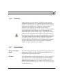
Rendezvous / ZeroConf
1.4
Rendezvous / ZeroConf
What Is
Rendezvous?
Rendezvous allows the automatic configuration of computers,
software services and peripheral devices in TCP/IP-based
networks. Rendezvous is meant for smaller networks (max. 1000
clients) which are to be set up quickly and where the use of a
DHCP server is not profitable. Rendezvous was initially
developed by Apple and is an inherent part of the Mac OS X
operating system.
Rendezvous mainly consists of three aspects:
•
•
•
Advertising of services
Discovery of services
Resolution of service names to IP addresses and TCP/IP ports
Automatic IP
address via
ZeroConf
Via ZeroConf, a print server that is connected to the network
automatically obtains an IP address. This IP address is taken from
the address range 169.254.0.1 to 169.254.255.254 which is
reserved for ZeroConf.
Services
The domain name service is used for additional Rendezvous
features in Apple networks. Since there is no central DNS server
in Rendezvous networks, each device and application has its own
small DNS server. This integrated DNS server (mDNS) collects
and administers the information of all participants in the net. In
addition to the features of a classical DNS server, the mDNS
server also saves the IP address, the service name and the offered
services of each participant.
What Happens
When the Print
Server is Turned on?
Once the print server is connected to the network and switched on,
the print server checks whether an IP address can be obtained from
a DHCP server or boot protocols. If this is not the case, the print
server assigns itself an IP address via ZeroConf. For this purpose,
Print Server Installation Manual
1-21
Rendezvous / ZeroConf
the print server picks an IP address at random from the address
range reserved for ZeroConf and sends a query to the network. If
this IP address has already been assigned elsewhere in the
network, the print server will receive a message. The print server
then sends another query with a different IP address. If the IP
address is available, it is saved in the print server.
What Happens next
in Apple Networks?
The print server repeats the same procedure for the service name.
The service name consists of the default print server name and the
name of the connected printer. After that, the print server starts its
printing and HTTP service and advertises both services in the
network. Now the print server is visible in the network and
printing can begin.
Integration of the
printer server in
other networks
In many cases, the print server is to be integrated into the actual
network after the automatic configuration in the 169.254.x.x
segment. In Apple networks you can use a browser to call the print
server homepage via Rendezvous and configure the print server
accordingly. In other networks you can do this using the
PRINTSERVER-NetTool. In the print server list of the
PRINTSERVER-NetTool the print server is displayed with its
ZeroConf IP address. For more information, please read the
"PRINTSERVER-NetTool" chapter on page 4-1 of the User
Manual.
You can also print a status page, check the print server's IP address
and then call the print server homepage. For more information,
please read the section "Printing the Status Page Using the Status
Button" on page 2-31 and the "Print Server Homepage" chapter on
page 3-1 of the User Manual.
1-22
Print Server Installation Manual
SNMP
1.5
SNMP
The SNMP protocol is used for providing and transferring
management information within the network. The SNMP
architecture is based on one or more management stations and
several network elements with one or more implemented network
management agents. The SNMP protocol is used for
communication between the management stations and the agents.
The management information is saved in so-called management
information bases (MIB).
Private MIB of the
Print Server
As an agent, the print server provides the standard 'MIB-II' and a
'private MIB'. All print server parameters and status information
are saved in the 'private MIB'. For more information, please read
the section "Parameter Description" on page B-2 of the User
Manual. The 'private MIB' is saved in the print server on delivery
and can be installed immediately. On the CD-ROM, you will find
a formal description of the 'private MIB' objects. If there is no
CD-ROM included in the delivery, please consult your retailer or
printer manufacturer.
Basic Functions
The system administrator can query and configure the print server
parameters from a management tool, such as OpenView or
TransView, by means of the SNMP protocol. In case of an error,
such as 'Paper empty', the print server automatically sends an error
message, the so-called trap, to pre-defined IP or IPX addresses. To
this end, the IP and IPX addresses must be configured and the
traps must be activated using the print server homepage, the
PRINTSERVER-NetTool, or FTP parameter transfer.
When using SNMP, make sure that:
9
Print Server Installation Manual
The TCP/IP protocol or the IPX protocol is installed on any
computer intended for printing.
1-23
SNMP
9
9
1-24
The print server is connected and the printer is turned on.
The IP address is saved in the print server.
Print Server Installation Manual
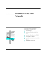
CHAPTER 2
Installation in WLAN
Networks
This chapter contains information
concerning the following topics:
Basic Principles
Installation for Use in the Ad-Hoc
Mode
Installation for Use with Unencrypted
Access Points
WLAN
Installation for Use with Protected
Access Points
Troubleshooting
Print Server Installation Manual
2-1
Basic Principles
2.1
Basic Principles
A WLAN print server can be operated in three different modes:
Ad-Hoc mode
•
Ad-Hoc mode (default setting)
•
Infrastructure mode
•
Auto mode
In the Ad-Hoc mode, the print server communicates directly with
another WLAN client (peer-to-peer). The Ad-hoc mode is set by
default on the print server via a jumper/switch.
Infrastructure
mode
The infrastructure mode is suitable for setting up large wireless
networks with several devices in different rooms. Communication
between the devices is done via an access point which is connected
to the network. The access point can be encrypted or unencrypted.
The infrastructure mode can be set via a jumper/switch on the print
server.
Auto mode
In the auto mode, the print server searches for an access point
which is connected to the network and which has the strongest
radio signal. The print server then tries to log into this access
point. If the access point is encrypted and the print server cannot
log in, the print server will search for an access point with a
weaker radio signal. If the print server finds an unencrypted access
point, it logs into this access point. If the print server does not find
any access point, it switches to the Ad-Hoc mode. The auto mode
can be set via a jumper/switch on the print server.
The IC155-WLANPOCKET is an exception. After the
IC155-WLANPOCKET is switched on, it searches for an access
point in the auto mode. If the print server finds an encrypted
access point, it does not search any further.
2-2
Print Server Installation Manual
Basic Principles
Procedure
Select one of the following options:
Installation for Use in the Ad-Hoc Mode
Installation for Use with Unencrypted Access Points
Installation for Use with Protected Access Points
Print Server Installation Manual
2-3
Installation for Use in the Ad-Hoc Mode
2.2
Installation for Use in the Ad-Hoc Mode
Requirements
Make sure that:
9
The PRINTSERVER-NetTool has been installed.
For more information, please read the section "Installing the
PRINTSERVER-NetTool" on page 4-3 of the User Manual.
9
The PC/Mac is in the Ad-Hoc mode.
9
The PC/Mac has the SSID 'wlsetup'.
Proceed as follows:
1. Start the PRINTSERVER-NetTool.
For more information, please read the section "Starting the
PRINTSERVER-NetTool" on page 4-4 of the User Manual.
2. Select the desired print server from the print server list.
3. Select the WLAN Wizard from the shortcut menu of the print
server.
4. Follow the instructions of the Wizard.
Enter 'wlsetup' or an arbitrary name as SSID.
5. Click 'Finish'.
6. If you have entered an arbitrary SSID into the WLAN Wizard,
re-enter this SSID on your PC/Mac.
7. Install the print server on the PC/Mac.
In order to do this, read the respective section for your
operating system in the Installation Manual.
2-4
Print Server Installation Manual
Installation for Use with Unencrypted Access Points
2.3
Installation for Use with Unencrypted
Access Points
Requirements
Make sure that:
9
The PRINTSERVER-NetTool has been installed.
For more information, please read the section "Installing the
PRINTSERVER-NetTool" on page 4-3 of the User Manual.
9
The PC/Mac is in the infrastructure mode.
9
The print server is set to the infrastruture mode via the
switch/jumper.
Proceed as follows:
1. Start the PRINTSERVER-NetTool.
For more information, please read the section "Starting the
PRINTSERVER-NetTool" on page 4-4 of the User Manual.
2. Select the desired print server from the print server list.
3. Select the WLAN Wizard from the shortcut menu of the print
server.
4. Follow the instructions of the Wizard.
If the print server is to be operated on a specific access point,
enter the SSID of the access point. If the print server is to be
operated on an arbitrary access point, do not enter an SSID.
5. Click 'Finish'.
6. Install the print server on the PC/Mac.
In order to do this, read the respective section for your
operating system in the Installation Manual.
Print Server Installation Manual
2-5
Installation for Use with Protected Access Points
2.4
Installation for Use with Protected Access
Points
The print server cannot automatically recognize the access point in
the network, if:
•
•
•
the access point is encrypted
an authentication is used
the access point does not disclose its SSID
In these cases, the print server has to be prepared for
communication with the access point.
As for encrypted access points, the same WEP key must be used
for the access point and the print server. Some access points
convert WEP keys that are entered as ASCII text into arbitrary
hexadecimal values. In this case, the WEP keys for the access
point and the print server do not match. It is therefore
recommended to use hexadecimal WEP keys.
Requirements
Make sure that:
9
The PRINTSERVER-NetTool has been installed.
For more information, please read the section "Installing the
PRINTSERVER-NetTool" on page 4-3 of the User Manual.
Proceed as follows:
1. Write down the WEP keys of the access point.
2. Temporarily switch your PC/Mac to the Ad-hoc mode.
3. Temporarily change your PC/Mac to the SSID 'wlsetup'.
2-6
Print Server Installation Manual
Installation for Use with Protected Access Points
4. Start the PRINTSERVER-NetTool.
For more information, please read the section "Starting the
PRINTSERVER-NetTool" on page 4-4 of the User Manual.
5. Select the WLAN Wizard from the shortcut menu of the print
server.
6. Follow the instructions of the Wizard.
Enter the SSID of the access point.
7. Click 'Finish'.
8. Switch the print server to the infrastruture mode using the
switch/jumper.
9. Switch your PC/Mac to the infrastructure mode.
10. Restore the default WLAN settings on the PC/Mac.
11. Install the print server on the PC/Mac.
In order to do this, read the respective section for your
operating system in the Installation Manual.
Print Server Installation Manual
2-7
Troubleshooting
2.5
Troubleshooting
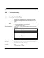
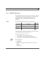
2.5.1
Interpreting the Status Page
In order to find out the print server's connection status in the
network, it is required to interpret the status page of the print
server.
Proceed as follows:
WLAN Parameter
1. Press the status button of the print server.
The status page is printed.
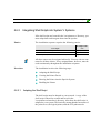
Under 'WLAN' you can obtain information about the following
parameters:
Parameter
Information
Mode
Mode which is set via the switch/jumper on the print server
Connection status
Determined WLAN status of the print server in the network
Network name
SSID:
- not configured in the infrastructure mode
- in the Ad-Hoc mode 'wlsetup' (factory default setting)
Current network name
SSID used
Channel
Radio channel
Encryption
Print server encryption
Speed
Transfer rate
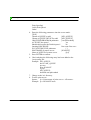
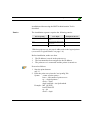
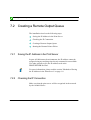
Examples
The following section gives some examples which will help you to
interpret the entries on the status page:
Example 1
Mode:
Auto
Connection status: Ad-Hoc
2-8
Print Server Installation Manual
Troubleshooting
Network name:
wlsetup
Encryption:
off
The print server is set to the auto mode via the switch/jumper.
Since the print server did not find any unencrypted access point, it
switches to the Ad-Hoc mode.
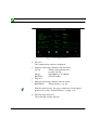
Example 2
Mode:
Auto
Connection status: Infrastructure
Network name:
SSID of an access point (example: Tsunami)
Encryption:
off
The print server is set to the auto mode via the switch/jumper. The
print server has found an unencrypted access point and therefore
switches to the infrastructure mode
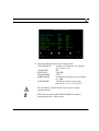
Example 3
Mode:
Infrastructure
Connection status: Infrastructure
Network name:
SSID of an access point (example: Tsunami)
Encryption:
on
The print server is set to the infrastruture mode via the
switch/jumper. The print server communicates with an encrypted
access point named 'Tsunami'.
2.5.2
Resetting Parameters
If the print server is not displayed in the print server list after the
installation of the PRINTSERVER-NetTool, the print server
parameters must be reset because you might have made a typing
error while entering the SSID or the WEP key.
For more information, please read the section "Resetting the
Parameters using the Status Button" on page 2-34 of the User
Manual.
Print Server Installation Manual
2-9
Troubleshooting
After the print server parameters have been reset, the WLAN print
server must be reinstalled.
2-10
Print Server Installation Manual
CHAPTER 3
Installation in Windows
Networks
This chapter contains information
concerning the following topics:
Basic Principles
Installation in Windows Networks
using the Printer Wizard
Installing in Windows Networks using
the PRINTSERVER Print Monitor
(Encrypted Printing)
Windows
Print Server Installation Manual
3-1
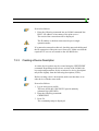
Basic Principles
3.1
Basic Principles
Print Server
Function
In a network, the print server acts as network connection for a
printer which is independent of the computer. The print data is
transferred from the individual computer to the network using the
PRINTSERVER Print Monitor. The print server receives the print
data and routes it to the printer.
What is the
PRINTSERVER
Print Monitor?
The PRINTSERVER Print Monitor constitutes the connecting
piece between the computer and the print server. It ensures the
transfer of print data from the computer to the print server by
means of direct TCP/IP ports. The PRINTSERVER Print Monitor
must be installed on every computer intended for printing. It is not
possible to share the printer.
Printer Wizard
The Printer Wizard is available for installing the print server.
The Printer Wizard is available in two versions:
•
Socket printing
printerwizardxp.exe for Windows XP, Windows 2000, and
Windows NT4.0
•
printerwizard9x.exe for Windows 98, Windows 95, and
Windows Me
With the assistance of the wizard, the print server is set up for
printing via TCP/IP ports (socket printing). In the process, the
PRINTSERVER Print Monitor and, under Windows XP and
Windows 2000, the required printer driver are automatically
installed.
Before installing the print server in Windows 98, Windows 95,
Windows Me, and Windows NT4.0, you must install the required
printer driver manually.
3-2
Print Server Installation Manual
Installation in Windows Networks using the Printer Wizard
3.2
Installation in Windows Networks using the
Printer Wizard
In this section, the installation of your PRINTSERVER with the
aid of the Printer Wizard is described.
Starting the Wizard
The wizard can either be started directly from the CD-ROM or can
be copied to a computer from where it can be started.
Before beginning the actual installation, you should have basic
knowledge of TCP/IP. For more information, please read the
section "Basic TCP/IP Terminology" on page 1-7.
Requirements
Before installation, make sure that:
9
9
9
The print server is connected and the printer is turned on.
The TCP/IP protocol is installed on every computer intended
for printing.
The printer driver is installed for Windows 98, Windows 95,
Windows Me, and Windows NT4.0.
Proceed as follows:
1. Start the Printer Wizard:
for Windows XP/2000/NT4.0
printerwizardxp.exe
for Windows 98/95/Me
printerwizard9x.exe
2. Follow the instructions of the wizard.
After the completion of the wizard, the print server and the
printer are installed.
Depending on the printer type, box and pocket print servers that
are connected to the printer's Centronics interface may have
printing problems. In this case, disable the 'bidirectionality' of the
Print Server Installation Manual
3-3
Installation in Windows Networks using the Printer Wizard
Windows driver under 'Properties'. This applies to the MINOLTA
QMS PagePro 1200W printer, for example.
3-4
Print Server Installation Manual
Installing in Windows Networks using the PRINTSERVER Print Monitor (Encrypted Printing)
3.3
Installing in Windows Networks using the
PRINTSERVER Print Monitor (Encrypted
Printing)
In this section, the installation of your PRINTSERVER in
Windows networks is described if printing is done via an
encrypted HTTP port.
The use of an http port comprises the following benefits:
•
•
Procedure
encryption of print data (optional)
using a proxy server, print jobs can be sent to a print server
via the Internet
The installation involves the following steps:
Installing the PRINTSERVER Print Monitor
Setting up the PRINTSERVER Print Monitor
3.3.1
Installing the PRINTSERVER Print Monitor
The PRINTSERVER Print Monitor can be found on the CD-ROM
enclosed in the product packaging of your print server. If there is
no CD-ROM included in the delivery, please consult your retailer
or printer manufacturer.
Print Server Installation Manual
3-5
Installing in Windows Networks using the PRINTSERVER Print Monitor (Encrypted Printing)
Proceed as follows:
1. Insert theCD-ROM into your CD-ROM drive.
The CD-ROM will start automatically.
2. Install the PRINTSERVER Print Monitor.
3.3.2
Setting up the PRINTSERVER Print Monitor
The PRINTSERVER Print Monitor is set up by adding and
configuring an HTTP port.
The following description refers to Windows XP. The handling
and outer appearance may slightly differ in other Windows
networks.
Proceed as follows:
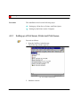
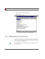
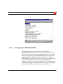
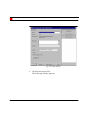
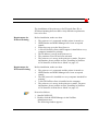
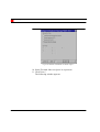
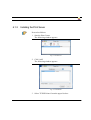
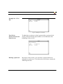
1. Select 'Properties' from the printer shortcut menu.
2. Select the 'Ports' tab.
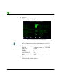
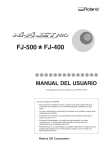
3. Click 'Add...'.
The following window appears:
Fig. 3-1: 'Printer Ports' window
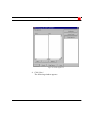
4. Select 'PRINTSERVER Print Monitor'.
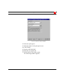
5. Click 'New Port...'.
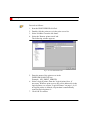
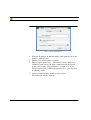
The following window appears:
3-6
Print Server Installation Manual
Installing in Windows Networks using the PRINTSERVER Print Monitor (Encrypted Printing)
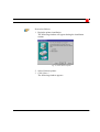
Fig. 3-2: 'HTTP printing' window
6. Activate 'HTTP printing'.
7. Confirm by clicking 'Next'.
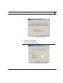
The following window appears:
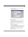
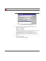
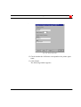
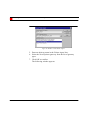
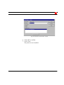
Fig. 3-3: 'HTTP Port Configuration' window
Print Server Installation Manual
3-7
Installing in Windows Networks using the PRINTSERVER Print Monitor (Encrypted Printing)
Data encryption
8. Enter the IP address or the host name of the print server.
9. Select the desired logical printer from the list. The default
setting is logical printer lp1. With box print servers, the port is
addressed via the logical printer. For more information, please
read the section "TCP/IP Ports" on page 1-15.
10. Select 'Encrypted printing' if you wish to encrypt print data.
Data encryption reduces the data transfer rate of you print
server. So maybe you would like to set up a second port
without data encryption.
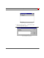
11. Confirm by clicking Next.
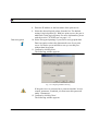
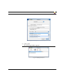
The following window appears:
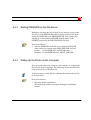
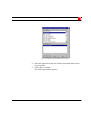
Fig. 3-4: Configuring SNMP monitoring
If the print server is protected by a password and the 'Access
control' parameter is enabled, you must enter this password
under 'Community'.
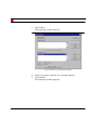
12. Confirm by clicking 'Next'.
The following window appears:
3-8
Print Server Installation Manual
Installing in Windows Networks using the PRINTSERVER Print Monitor (Encrypted Printing)
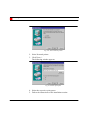
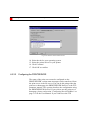
Fig. 3-5: Configuring the proxy server
13. Enable 'Use proxy', if you want to print using a proxy server.
14. Enter the IP address or the name of the proxy server, if
necessary.
15. Enter the port number of the proxy server, if necessary.
16. Confirm by clicking 'Next'.
17. Check your settings.
18. Click 'Finish'.
Print Server Installation Manual
3-9
Installing in Windows Networks using the PRINTSERVER Print Monitor (Encrypted Printing)
3-10
Print Server Installation Manual
CHAPTER 4
Installation in Novell
Networks
This chapter contains information
concerning the following topics:
Basic Principles
Installing in NetWare 6/5/4 Networks
in Print Server Mode
Installing in NetWare 6/5 Networks in
Print Server Mode (Pure IP)
Novell
Installing in NetWare 6/5/4 Networks
in Remote Printer Mode
Installing in NetWare 6/5 Networks
with NDPS Gateways
Tips and Tricks
Print Server Installation Manual
4-1
Basic Principles
4.1
Basic Principles
What Happens
When Printing in
Novell Networks?
The printing sequence in Novell networks has three steps:
•
•
•
Print data rerouting
Intermediate print data storage in a print queue
Printout
Print data that is transferred from an application to a printer
interface, such as LPT1, is rerouted to the NetWare file server. The
incoming print job is added to a print queue on the file server. The
print job is then routed either to a print server connected to the
printer or to a remote printer, where it is then printed out.
Which Protocols are
Used?
The IPX protocol is used as a network protocol in all Novell
networks. The IPX protocol must be installed on every
workstation which is to provide printing services. If remote
printing is selected, the SPX protocol is then used as the network
protocol between the file server and the PRINTSERVER.
Print Server,
Network Printer, or
Remote Printer?
Your print server can be installed in Novell networks in various
modes. Print server mode is available in all Novell NetWare
networks. In Novell NetWare 6/5/4 networks, the print server can
also be installed as network printer (NPRINTER). In Novell
NetWare 6/5 networks, print data can also be sent via NDPS
gateways. Each mode has certain advantages and disadvantages
that will be described below.
Print Server Mode
In the print server mode, the PRINTSERVER carries out an
automatic recognition of the network structure. After activation,
the PRINTSERVER transfers broadcast data packets having the
IEEE_802.2, IEEE_802.3, ETHERNET_II and SNAP Novell
frame types to the net. This gives the print server a general
overview of the existing bindery and NDS servers as well as the
4-2
Print Server Installation Manual
Basic Principles
installed print queues. The print server logs itself on and
automatically recognizes changes in the network structure by
searching the network for new servers every two minutes. This time
period for the new recognition of the network structure, the
so-called refresh time, and the used Novell protocol headers can be
configured using either the print server homepage, the
PRINTSERVER-NetTool, or parameter transfer via FTP.
In the print server mode, the PRINTSERVER queries at regular
intervals whether any file servers have print jobs in their
respective print queues. If any print job exists, the
PRINTSERVER collects the print data and sends it to the printer
for processing. This time period of polling the print queue, the
so-called poll time, can be configured using either the print server
homepage or the PRINTSERVER-NetTool.
Every print server in the print server mode requires a Novell
NetWare user license. The data throughput during print server
mode is comparatively high. The PRINTSERVER can service 16
bindery servers and 8 NDS servers (24 NDS servers when bindery
is turned off). You can install and assign up to a total of 16 print
queues to a print server.
Remote printer mode
In remote printer mode, a Novell print server must be started on
the Novell file server. This Novell print server is the module
PSERVER.NLM.
In the remote printer mode the print jobs are routed from the
PSERVER to the PRINTSERVER. The PRINTSERVER adopts
the function of the NPRINTER in NetWare 6/5/4 networks. The
print server routes status information, such as 'Ready to Print' or
'Paper empty' to the PSERVER. If the PSERVER receives print
jobs from the computer, these jobs are routed to the
PRINTSERVER.
Print Server Installation Manual
4-3
Basic Principles
In remote printer mode, the print server does not need a Novell
NetWare user license. The PRINTSERVER requires
comparatively fewer resources in the remote printer mode and
does not overload the network. PSERVER can administer a
maximum of 256 print servers in Novell NetWare 4 networks
while in remote printer mode.
NDPS Gateways
The NDPS Gateway functions as an interface between the print
server and the Novell client and administers the printer agent. The
advantages of using NDPS Gateways are the automatic installation
of drivers and the improved monitoring of the various printer
states.
For more information, please read the documentation issued by
Novell regarding the NDPS.
What is the Novell
Name?
The Novell name can be used instead of the default print server
name. You can use the Novell name whenever a print server needs
a meaningful name, such as ICxxxxxx. The Novell name can be
assigned using either the print server homepage, the
PRINTSERVER-NetTool or the FTP parameter transfer.
Procedure
Which procedures can be selected?
Installing in NetWare 6/5/4 Networks in Print Server Mode
Installing in NetWare 6/5 Networks in Print Server Mode
(Pure IP)
Installing in NetWare 6/5/4 Networks in Remote Printer
Mode
Installing in NetWare 6/5 Networks with NDPS Gateways
4-4
Print Server Installation Manual
Installing in NetWare 6/5/4 Networks in Print Server Mode
4.2
Installing in NetWare 6/5/4 Networks in Print
Server Mode
In this section, the installation of your PRINTSERVER in Novell
NetWare 6/5/4 networks for the NDS printout in print server mode
is described. A wizard guides you through an easy and safe
installation in the PRINTSERVER-NetTool. In a single step, you
can install a print server, a printer, and a print queue.
Before beginning the actual installation, you should have basic
knowledge of Novell networks. For more information, please read
the section "Basic Principles" on page 4-2.
Before installation, make sure that:
9
9
9
Procedure
The print server is connected and the printer is turned on.
The IPX protocol is installed on every computer intended for
printing.
A Novell NetWare client is installed on the computer.
The installation involves the following steps:
Setting up a Print Server, Printer, and Print Queue
Setting Up the Printer on the Computer
4.2.1
Setting up a Print Server, Printer, and Print Queue
Proceed as follows:
1. Start the PRINTSERVER-NetTool.
Print Server Installation Manual
4-5
Installing in NetWare 6/5/4 Networks in Print Server Mode
2. Click the print server in the print server list.
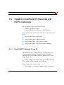
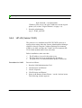
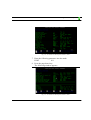
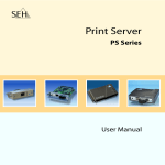
3. Select 'NetWare Wizard' from the 'Installation' menu.
The following window appears:
Fig. 4-1: NetWare Wizard
4. Select 'NDS Installation'.
5. Follow the instructions of the installation routine.
4.2.2
Setting Up the Printer on the Computer
Now the printer has to be set up on each computer or workstation
that is to be used for printing. The following section describes the
setup of the printer in Windows 98.
If desired, please see the Windows Manual for instructions on how
to set up printers.
4-6
Print Server Installation Manual
Installing in NetWare 6/5/4 Networks in Print Server Mode
Proceed as follows:
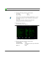
1. Begin the printer installation.
The following window will appear during the installation
routine:
Fig. 4-2: Select Network printer
2. Select Network printer.
3. Click 'Next >'.
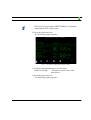
The following window appears:
Print Server Installation Manual
4-7
Installing in NetWare 6/5/4 Networks in Print Server Mode
Fig. 4-3: Select print queue
4. Select the respective print queue.
5. Follow the instructions of the installation routine.
4-8
Print Server Installation Manual
Installing in NetWare 6/5 Networks in Print Server Mode (Pure IP)
4.3
Installing in NetWare 6/5 Networks in Print
Server Mode (Pure IP)
In this section, the installation of your PRINTSERVER in
IP-based (Pure IP) Novell NetWare 6/5 networks for the NDS
printout in print server mode is described. Quick Setup in the
NetWare Administrator enables easy, safe installation. In a single
step, you can install a print server, a printer, and a print queue.
Before beginning the actual installation, you should have basic
knowledge of Novell networks. For more information, please read
the section "Basic Principles" on page 4-2.
Entries
The installation sequence requires the following entries:
NetWare Administrator
User input
Example in the text
Print Server Name
<name of the
PRINTSERVER> or
Novell name
Printer Name
<Printer Name> + #1 to #8 MY_PRINTER#1
for the logical printer
Print Queue Name
<arbitrary name>
IC0001FF
MY_QUEUE
Before installation, make sure that:
9
9
9
9
9
Print Server Installation Manual
The print server is connected and the printer is turned on.
IP has been set up on the Novell server.
A Novell NetWare client with IP support is installed on every
computer intended for printing.
The IP address is saved in the print server.
The parameter 'Pure IP' has been activated.
4-9
Installing in NetWare 6/5 Networks in Print Server Mode (Pure IP)
Procedure
The installation involves the following steps:
Setting up a Print Server, Printer, and Print Queue
Setting Up the Printer on the Computer
4.3.1
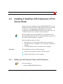
Setting up a Print Server, Printer and Print Queue
Proceed as follows:
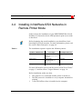
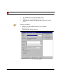
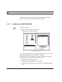
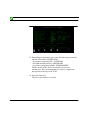
1. Start the NetWare Administrator.
The following window appears:
Fig. 4-4: NetWare Administrator
2. Mark the context.
4-10
Print Server Installation Manual
Installing in NetWare 6/5 Networks in Print Server Mode (Pure IP)
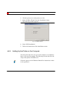
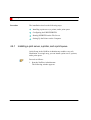
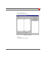
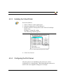
3. Select the 'Print Services Quick Setup (Non-NDPS)' menu
item in the 'Tools' menu.
The following window appears:
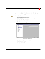
Fig. 4-5: 'Print Services Quick Setup (Non-NDPS)' window
4. Enter the print server name in the 'Print Server name' box.
Syntax: ICxxxxxx
Example: IC0001FF
Here you may also use the Novell name of the print server if
you assign this name using the print server homepage, the
PRINTSERVER-NetTool, or FTP parameter transfer.
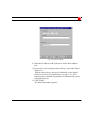
5. Enter an arbitrary name and a logical printer in the 'Printer
Name' box.
Syntax: <Printer Name>#1 - #8
Example: MY_PRINTER#1
The logical printers are defined using extensions #1 - #8. With
box print servers, the port is addressed via the logical printer
(see section "Logical Printers" on page 1-4). If no logical
printer is defined, all print data is automatically routed to
logical printer #1.
6. Enter an arbitrary name in the 'Print Queue Name' box.
Example: MY_QUEUE
Print Server Installation Manual
4-11
Installing in NetWare 6/5 Networks in Print Server Mode (Pure IP)
7. If necessary, select the correct volume.
8. Click 'Create'.
The tree looks as follows:
Fig. 4-6: Installed print server in print server mode
4.3.2
Setting Up the Printer on the Computer
Now the printer has to be set up on each computer or workstation
that is to be used for printing. The following section describes the
setup of the printer in Windows 98.
If desired, please see the Windows Manual for instructions on how
to set up printers.
4-12
Print Server Installation Manual
Installing in NetWare 6/5 Networks in Print Server Mode (Pure IP)
Proceed as follows:
1. Begin the printer installation.
The following window will appear during the installation
routine:
Fig. 4-7: Select Network printer
2. Select Network printer.
3. Click 'Next >'.
The following window appears:
Print Server Installation Manual
4-13
Installing in NetWare 6/5 Networks in Print Server Mode (Pure IP)
Fig. 4-8: Select print queue
4. Select the respective print queue.
5. Follow the instructions of the installation routine.
4-14
Print Server Installation Manual
Installing in NetWare 6/5/4 Networks in Remote Printer Mode
4.4
Installing in NetWare 6/5/4 Networks in
Remote Printer Mode
In this section, the installation of your PRINTSERVER in Novell
NetWare 6/5/4 networks for the NDS printout in print server mode
is described.
Before beginning the actual installation, you should have basic
knowledge of Novell networks. For more information, please read
the section "Basic Principles" on page 4-2.
Entries
The installation sequence requires the following entries:
NetWare Administrator
User input
Example in the text
Print Server Name
<name of
PSERVER.NLM> on the
file server
MY_PRINT_SERVER
Printer Name
<name of the
PRINTSERVER> or
Novell name
IC0001FF
Print Queue Name
<arbitrary name>
MY_QUEUE
For more information, please read the section "Print Server Name"
on page 1-3 and the section "Logical Printers" on page 1-4.
Before installation, make sure that:
9
9
9
Print Server Installation Manual
The print server is connected and the printer is turned on.
The IPX protocol is installed on every computer intended for
printing.
A Novell NetWare client is installed on the computer.
4-15
Installing in NetWare 6/5/4 Networks in Remote Printer Mode
Procedure
The installation involves the following steps:
Installing a print server, a printer, and a print queue
Configuring the PRINTSERVER
Starting PSERVER on the File Server
Setting Up the Printer on the Computer
4.4.1
Installing a print server, a printer, and a print queue
Quick Setup in the NetWare Administrator enables easy, safe
installation. In a single step, you can install a print server, a printer,
and a print queue.
Proceed as follows:
1. Start the NetWare Administrator.
The following window appears:
4-16
Print Server Installation Manual
Installing in NetWare 6/5/4 Networks in Remote Printer Mode
Fig. 4-9: NetWare Administrator
2. Mark the context.
3. Select the 'Print Services Quick Setup (Non-NDPS)' menu
item in the 'Tools' menu.
The following window appears:
Print Server Installation Manual
4-17
Installing in NetWare 6/5/4 Networks in Remote Printer Mode
Fig. 4-10: 'Print Services Quick Setup (Non-NDPS)' window
4. Enter an arbitrary name for the print server in the 'Print Server
name' box.
MY_PRINT_SERVER
5. Enter the name of the print server in the 'Printer Name' box.
Syntax: ICxxxxxx
Example: IC0001FF
6. Enter an arbitrary name in the 'Print Queue Name' box.
MY_QUEUE
7. If necessary, select the correct volume.
8. Click 'Create'.
The tree looks as follows:
4-18
Print Server Installation Manual
Installing in NetWare 6/5/4 Networks in Remote Printer Mode
Fig. 4-11: Installed Print Server in Remote Printer Mode
4.4.2
Configuring the PRINTSERVER
The name of the print server must be configured on the
PRINTSERVER, so that status messages can be transferred from
the print server to the file server. You can do this using either the
print server homepage, the PRINTSERVER-NetTool, or the FTP
parameter transfer. In this section, the configuration using the
PRINTSERVER-NetTool is described. If you wish to use the print
server homepage, please read section "Configuring Novell
NetWare" on page 3-16 in the User Manual. If you wish to use the
FTP parameter transfer function, please read section "Configuring
Parameters via FTP" on page B-14 in the User Manual.
Print Server Installation Manual
4-19
Installing in NetWare 6/5/4 Networks in Remote Printer Mode
Proceed as follows:
1.
2.
3.
4.
Start the PRINTSERVER-NetTool.
Double-click the print server in the print server list.
Select 'NetWare' from the left frame.
Select the 'Remote printer mode' tab.
The following window appears:
Fig. 4-12: Enter PSERVER Name
5. Enter the name of the print server in the
'PSERVER.NLM/.EXE' box.
Example: MY_PRINT_SERVER
6. Select a logical printer from the 'Logical printer' box, if
necessary. With box print servers, the port is addressed via the
logical printer (see section "Logical Printers" on page 1-4). If
no logical printer is defined, all print data is automatically
routed to logical printer #1.
7. Click 'OK' to confirm.
4-20
Print Server Installation Manual
Installing in NetWare 6/5/4 Networks in Remote Printer Mode
4.4.3
Starting PSERVER on the File Server
During the last step, the Novell print server must be set up on the
file server in the PSERVER module in order to transfer the print
data from PSERVER to the PRINTSERVER. This requires the
starting up of the module PSERVER with the name of the
PSERVER entered in the PRINTSERVER-NetTool.
Proceed as follows:
1. Start the PSERVER on the file server with the PSERVER
name which you entered in the PRINTSERVER-NetTool.
Syntax: LOAD PSERVER <PSERVER name>
Example: LOAD PSERVER MY_PRINT_SERVER
4.4.4
Setting Up the Printer on the Computer
Now the printer has to be set up on each computer or workstation
that is to be used for printing. The following section describes the
setup of the printer in Windows 98.
If desired, please see the Windows Manual for instructions on how
to set up printers.
Proceed as follows:
1. Begin the printer installation.
The following window will appear during the installation
routine:
Print Server Installation Manual
4-21
Installing in NetWare 6/5/4 Networks in Remote Printer Mode
Fig. 4-13: Select Network printer
2. Select Network printer.
3. Click 'Next >'.
The following window appears:
Fig. 4-14: Select print queue
4. Select the respective print queue.
5. Follow the instructions of the installation routine.
4-22
Print Server Installation Manual
Installing in NetWare 6/5 Networks with NDPS Gateways
4.5
Installing in NetWare 6/5 Networks with
NDPS Gateways
The installation involves the following steps:
•
•
Setting up the Printer Agent
Setting up the Printer in the Novell Print Manager
There are different options involved in the set up of the printer
agent:
Novell NDPS Gateway: lpr via IP
Novell NDPS Gateway: Remote Printer
Novell NDPS Gateway: Print Queue-Based
Setting up the Printer in the Novell Printer Manager
4.5.1
Novell NDPS Gateway: lpr via IP
This installation uses TCP/IP (Pure IP) as print protocol. All
IPX-based communication is disabled. Status information
regarding the Novell NetWare status of the print server is no
longer displayed.
If you are printing via IP, Novell can be turned off on the print
server. In this case the network load is reduced.
Before installation, make sure that:
9
Print Server Installation Manual
The print server is connected and the printer is turned on.
4-23
Installing in NetWare 6/5 Networks with NDPS Gateways
9
9
9
The IP address is saved in the print server.
IP has been set up on the Novell file server.
NDPS Broker and NDPS Manager have been set up and
started.
Proceed as follows:
1. Double-click the NDPS Manager in the NetWare
Administrator tree.
The following window appears:
Fig. 4-15: NDPS Manager
4-24
Print Server Installation Manual
Installing in NetWare 6/5 Networks with NDPS Gateways
2. Click 'Printer Agent List'.
The following window appears:
Fig. 4-16: Printer Agent List
3. Click 'New...'
The following window appears:
Print Server Installation Manual
4-25
Installing in NetWare 6/5 Networks with NDPS Gateways
Fig. 4-17: Window 'Create Printer Agent'
4. Enter an arbitrary name in the 'Printer Agent' box.
5. Select the Novell printer gateway from the list of gateway
types.
6. Click 'OK' to confirm.
The following window appears:
4-26
Print Server Installation Manual
Installing in NetWare 6/5 Networks with NDPS Gateways
Fig. 4-18: Window 'Novell PDS for Printer Agent ...'
7. Select the printer from the list which corresponds most closely
to your model.
8. Click 'OK' to confirm.
The following window appears:
Print Server Installation Manual
4-27
Installing in NetWare 6/5 Networks with NDPS Gateways
Fig. 4-19: Window 'Port Handler for Printer Agent ...'
9. Select 'Remote (LPR on IP)' as your protocol.
10. Click 'Next >'.
The following window appears:
4-28
Print Server Installation Manual
Installing in NetWare 6/5 Networks with NDPS Gateways
Fig. 4-20: Enter IP Address
11. Enter the IP address of the print server in the 'Host Address'
box.
12. If necessary, enter a logical printer with lp1 - lp8 in the 'Printer
Name' box.
With box print servers, the port is addressed via the logical
printer (see section "Logical Printers" on page 1-4). If no
logical printer is defined, all print data is automatically routed
to logical printer #1.
13. Click 'Finish'.
The following window appears:
Print Server Installation Manual
4-29
Installing in NetWare 6/5 Networks with NDPS Gateways
Fig. 4-21: Window 'Select Printer Drivers'
14. Select the tab for your operating system.
15. Select the printer driver for your printer.
16. Click 'Continue'.
17. Click 'OK' to confirm.
4.5.2
Novell NDPS Gateway: Remote Printer
Note that the Novell name, the remote printer name (name of the
PSERVER.NLM), the printer agent name, and the SAP name must
correspond!
Before installation, make sure that:
9
4-30
The print server is connected and the printer is turned on.
Print Server Installation Manual
Installing in NetWare 6/5 Networks with NDPS Gateways
9
9
9
Procedure
NDPS Broker and NDPS Manager have been set up and
started.
The IPX protocol is installed on every computer intended for
printing.
A Novell NetWare client is installed on the computer.
The installation involves the following steps:
Setting up the Printer Agent
Configuring the PRINTSERVER
Starting PSERVER on the File Server
4.5.2.1
Setting up the Printer Agent
Proceed as follows:
1. Double-click the NDPS Manager in the NetWare
Administrator tree.
The following window appears:
Print Server Installation Manual
4-31
Installing in NetWare 6/5 Networks with NDPS Gateways
Fig. 4-22: NDPS Manager
2. Click 'Printer Agent List'.
The following window appears:
4-32
Print Server Installation Manual
Installing in NetWare 6/5 Networks with NDPS Gateways
Fig. 4-23: Printer Agent List
3. Click 'New...'
The following window appears:
Print Server Installation Manual
4-33
Installing in NetWare 6/5 Networks with NDPS Gateways
Fig. 4-24: Window 'Create Printer Agent'
4. Enter the print server name in the 'Printer Agent Name
(PA-Printer Agent)' box.
Syntax: ICxxxxxx
Example: IC0001FF
Here, you may also use the Novell name of the print server if
you assign it using the print server homepage, the
PRINTSERVER-NetTool, or the FTP parameter transfer.
5. Select the Novell printer gateway from the list of gateway
types.
6. Click 'OK' to confirm.
The following window appears:
4-34
Print Server Installation Manual
Installing in NetWare 6/5 Networks with NDPS Gateways
Fig. 4-25: Window 'Novell PDS for Printer Agent ...'
7. Select the printer from the list which corresponds most closely
to your model.
8. Click 'OK' to confirm.
The following window appears:
Print Server Installation Manual
4-35
Installing in NetWare 6/5 Networks with NDPS Gateways
Fig. 4-26: Window 'Port Handler for Printer Agent ...'
9. Select 'Remote (rprinter on IPX)' as your protocol.
10. Select 'Other' as port type.
11. Click 'Next >'.
The following window appears:
4-36
Print Server Installation Manual
Installing in NetWare 6/5 Networks with NDPS Gateways
Fig. 4-27: Check SAP name
12. Check whether the SAP name corresponds to the printer agent
name.
13. Click 'Finish'.
The following window appears:
Print Server Installation Manual
4-37
Installing in NetWare 6/5 Networks with NDPS Gateways
Fig. 4-28: Window 'Select Printer Drivers'
14. Select the tab for your operating system.
15. Select the printer driver for your printer.
16. Click 'Continue'.
17. Click 'OK' to confirm.
4.5.2.2
Configuring the PRINTSERVER
The name of the print server must be configured on the
PRINTSERVER, so that status messages can be transferred from
the print server to the file server. You can do this using either the
print server homepage, the PRINTSERVER-NetTool, or the FTP
parameter transfer. This section describes the configuration using
the PRINTSERVER-NetTool. If you wish to use the print server
homepage, please read section "Configuring Novell NetWare" on
page 3-16 in the User Manual. If you wish to use the FTP
4-38
Print Server Installation Manual
Installing in NetWare 6/5 Networks with NDPS Gateways
parameter transfer function, please read section "Configuring
Parameters via FTP" on page B-14 in the User Manual.
Proceed as follows:
1.
2.
3.
4.
Start thePRINTSERVER-NetTool.
Double-click the print server in the print server list.
Select 'NetWare' from the left frame.
Select the 'Remote Printer Mode' tab.
The following window appears:
Fig. 4-29: Enter PSERVER Name
5. Enter the name of the print server in the
'PSERVER.NLM/.EXE' box.
Example: IC0001FF
Print Server Installation Manual
4-39
Installing in NetWare 6/5 Networks with NDPS Gateways
6. Select a logical printer from the 'Logical printer' box, if
necessary. With box print servers, the port is addressed via the
logical printer (see section "Logical Printers" on page 1-4). If
no logical printer is defined, all print data is automatically
routed to logical printer #1.
7. Click 'OK' to confirm.
4.5.2.3
Starting the PSERVER on the File Server
In the last step, the Novell print server must be set up on the file
server in the PSERVER module in order to transfer the print data
from PSERVER to the PRINTSERVER. This requires the starting
up of the module PSERVER with the name of the PSERVER
entered in the PRINTSERVER-NetTool.
Proceed as follows:
1. Start the PSERVER on the file server with the PSERVER
name which you entered in the PRINTSERVER-NetTool.
Syntax: LOAD PSERVER <PSERVER name>
Example: LOAD PSERVER IC0001FF
4.5.3
Novell NDPS Gateway: Print Queue-Based
If the print server is password-protected, this password will be
demanded during the installation routine. The following
description includes this password demand. If no password has
been assigned, you can skip the respective passages.
4-40
Print Server Installation Manual
Installing in NetWare 6/5 Networks with NDPS Gateways
The installation of the print server for IP-based (Pure IP) or
IPX-based printing does not differ. Only different requirements
have to be met.
Requirements for
IP-based Printing
Before installation, make sure that:
9
9
9
9
9
9
9
Requirements for
IPX-based Printing
The print server is connected and the printer is turned on.
NDPS Broker and NDPS Manager have been set up and
started.
IP has been set up on the Novell server.
A Novell NetWare client with IP support is installed on every
computer intended for printing.
The IP address is saved in the print server.
The parameter 'Pure IP' has been activated.
The print server is set up in the print server mode. For more
information, please read the section "Installing in NetWare
6/5/4 Networks in Print Server Mode" on page 4-5.
Before installation, make sure that:
9
9
9
9
9
The print server is connected and the printer is turned on.
NDPS Broker and NDPS Manager have been set up and
started.
The IPX protocol is installed on every computer intended for
printing.
A Novell NetWare client is installed on the computer.
The print server is set up in the print server mode. For more
information, please read the section "Installing in NetWare
6/5/4 Networks in Print Server Mode" on page 4-5.
Proceed as follows:
1. Start RCONSOLE.
2. Double-click the NDPS Manager in the NetWare
Administrator tree.
The following window appears:
Print Server Installation Manual
4-41
Installing in NetWare 6/5 Networks with NDPS Gateways
Fig. 4-30: NDPS Manager
3. Click 'Printer Agent List'.
The following window appears:
4-42
Print Server Installation Manual
Installing in NetWare 6/5 Networks with NDPS Gateways
Fig. 4-31: Printer Agent List
4. Click 'New...'
The following window appears:
Print Server Installation Manual
4-43
Installing in NetWare 6/5 Networks with NDPS Gateways
Fig. 4-32: Window 'Create Printer Agent'
5. Enter an arbitrary name in the 'Printer Agent' box.
6. Select the Novell printer gateway from the list of gateway
types.
7. Click 'OK' to confirm.
The following window appears:
4-44
Print Server Installation Manual
Installing in NetWare 6/5 Networks with NDPS Gateways
Fig. 4-33: Window 'Novell PDS for Printer Agent ...'
8. Select the printer from the list which corresponds most closely
to your model.
9. Click 'OK' to confirm.
The following window appears:
Print Server Installation Manual
4-45
Installing in NetWare 6/5 Networks with NDPS Gateways
Fig. 4-34: Window 'Port Handler for Printer Agent ...'
10. Select 'Forward Jobs to a Queue' as a protocol.
11. Click 'Next >'.
The following window appears:
4-46
Print Server Installation Manual
Installing in NetWare 6/5 Networks with NDPS Gateways
Fig. 4-35: Entries for the port handler
12. Select the print queue.
13. Select the name of the print queue user.
14. Click 'Finish'.
15. Switch to RCONSOLE.
16. Enter the user password.
17. Switch back to the printer agent.
The following window appears:
Print Server Installation Manual
4-47
Installing in NetWare 6/5 Networks with NDPS Gateways
Fig. 4-36: Window 'Select Printer Drivers'
18. Select the tab for your operating system.
19. Select the printer driver for your printer.
20. Click 'Continue'.
21. Click 'OK' to confirm.
22. Select the tab for your operating system.
4.5.4
Setting up the Printer in the Novell Printer Manager
Proceed as follows:
1. Start the Novell Printer Manager.
The following window appears:
4-48
Print Server Installation Manual
Installing in NetWare 6/5 Networks with NDPS Gateways
Fig. 4-37: Window 'Novell Printer Manager'
2. Select the menu item 'New…' in the 'Printer' menu.
The following window appears:
Fig. 4-38: Window 'Novell Printers'
Print Server Installation Manual
4-49
Installing in NetWare 6/5 Networks with NDPS Gateways
3. Click 'Add>>'.
The following window appears:
Fig. 4-39: Window 'Novell Printers' expanded
4. Select your printer from the list 'Available Printers'.
5. Click 'Install...'
The following window appears:
4-50
Print Server Installation Manual
Installing in NetWare 6/5 Networks with NDPS Gateways
Fig. 4-40: Window 'Novell Printers - Install'
6. Click 'OK' to confirm.
7. Click 'Close'.
The printer is now installed.
Print Server Installation Manual
4-51
Tips and Tricks
4.6
Tips and Tricks
The print server services up to a total of 16 print queues. For every
extra print queue, the steps listed above must be repeated.
If the print server in Novell NetWare 4.x networks also services
print queues installed on other volumes in the network,
PCONSOLE can be used to select a different volume, and the
installation can be repeated accordingly.
4-52
Print Server Installation Manual
CHAPTER 5
Installation in UNIX
Networks
This chapter contains information
concerning the following topics:
Basic Principles
Assigning the IP Address to the Host
Name
Saving the IP Address in the Print
Server
Printing via the LPD Protocol
UNIX
Printing via TCP/IP Ports
Printing via Shell Scripts
Print Server Installation Manual
5-1
Basic Principles
5.1
Basic Principles
Printing in UNIX networks varies depending on the UNIX system
version used. The two most commonly used printing methods are
remote printing via the LPD protocol and direct printing via
TCP/IP ports. If both methods are not available, you can then print
via shell scripts.
Printing via the LPD
Protocol
Several UNIX systems support the linkage of network printers via
the LPD protocol. With this method, the PRINTSERVER is
integrated into the spooler as a remote printer. The user host
transfers the print data to the printer by means of the print server.
Printing via TCP/IP
Ports
Several UNIX systems support the linkage of network printers by
means of direct TCP/IP connection. Print data can be transferred
from the spooler to the print server via TCP/IP ports.
Printing via Shell
Scripts
When printing via shell scripts, a printer, which the UNIX spooler
considers to be local, is installed. The printer is then entered into
the UNIX spooler system. The shell scripts route the print data to
the print server by means of FTP. The *.sh shell scripts are sample
scripts for the default printer interfaces of the 'lpsched,' 'lpd,' and
'qdaemon' spoolers supported by the print server.
The following shell scripts are available:
•
•
•
Printing Without a
Spooler
5-2
aix.sh (for AIX systems)
bsd.sh (for BSD systems)
sys5.sh (for System V)
You can also send print data directly to the print server by means
of FTP while bypassing the spooler. This method of network
printing is mainly used for testing the print server after
installation.
Print Server Installation Manual
Basic Principles
Supported Spoolers
The print server supports the 'lpsched' (System V), 'lpd' (BSD),
and 'qdaemon' (AIX) spoolers. Please consult your system
administrator or your system manual to find out which UNIX
version or spooler is installed on your computer. If your system
has the '/usr/lib/lpsched' file, you most probably have System V; if
your system has the '/usr/lib/lpd' and '/etc/printcap' files, you have
BSD.
Procedure
The installation involves the following steps:
Assigning the IP Address to the Host Name
Saving the IP Address in the Print Server
Printing via the LPD Protocol
Printing via TCP/IP Ports
Printing via Shell Scripts
Print Server Installation Manual
5-3
Assigning the IP Address to the Host Name
5.2
Assigning the IP Address to the Host Name
As a rule, hosts can be addressed at the user command level
('ping,' 'ftp,' and 'tftp,' for example), with their host names, or
directly with their IP addresses. The host name is most commonly
used.
In this case, the host name must be assigned to the IP address. This
is carried out either in the local 'etc/hosts' file or on a DNS server.
The following section will describe the assignment of the host
name to the IP address using the 'hosts' file. For more information,
please read the relevant section in the documentation of your
operating system.
Assignment Files
The assignment of the host names to the IP addresses and the IP
addresses to the hardware addresses is saved in the following files:
File
Assignment
/etc/hosts
Assignment of host names to IP addresses
/etc/bootptab
Assignment of IP addresses to hardware addresses if the BOOTP boot protocol
is used
/etc/rarpd.cf
Assignment of IP addresses to hardware addresses if the BOOTP boot protocol
is used
/etc/ethers
Assignment of IP addresses to hardware addresses if the RARP boot protocol
is used
The '/etc/hosts' file exists on every computer in the network,
whereas the other files usually only exist if the listed network
services are implemented. Depending on the UNIX system used,
the files may also be located in different directories.
The computer from which this installation is carried out must be in
the same (sub)network as the print server. Later, the printer may be
located anywhere in the network.
5-4
Print Server Installation Manual
Assigning the IP Address to the Host Name
Proceed as follows:
1. Log on as root.
2. Add the following entry into the '/etc/hosts' file:
Syntax: <IP address> <host name>
Example: 192.168.0.123 IC0001FF
Print Server Installation Manual
5-5
Saving the IP Address in the Print Server
5.3
Saving the IP Address in the Print Server
There are several methods available for saving the IP address in
the print server.
For more information, please read the section "Methods of Saving
the IP Address in the Print Server" on page 1-8.
Select one of the following methods:
Saving the IP Address via BOOTP
Saving the IP Address via RARP
Saving the IP Address using the 'arp' and 'ping' Commands
5.3.1
Saving the IP Address via BOOTP
If the BOOTP boot protocol has been installed in your network,
you must edit the '/etc/bootptab' file. The procedure is somewhat
different for ULTRIX systems. If you use an ULTRIX system,
please read the section "Procedure for ULTRIX" on page 5-7.
Please note that (optional) periods separate the address groups of
the hardware addresses in this file, whereas colons separate fields
from each other in an individual entry. In ULTRIX and some other
UNIX systems, the individual fields of an entry are separated from
each other using the tab character.
5-6
Print Server Installation Manual
Saving the IP Address in the Print Server
Proceed as follows:
1. Add the following entry to the '/etc/bootptab' file:
Syntax for Ethernet:<host name>:ht=ether:ha=<hardware
address>:ip=<IP address>
Example for Ethernet:
IC0001FF:ht=ether:ha=00.c0.eb.00.01.ff:ip=192.168.0.123
Syntax for Token Ring: <host name>:ht=tr:ha=<hardware
address>:ip=<IP address>
Example for Token Ring:
IC0001FF:ht=tr:ha=00.c0.eb.00.01.ff:ip=192.168.0.123
2. Please make sure that the 'bootp' print daemon rereads the
configuration file.
Procedure for
ULTRIX
5.3.2
Proceed as follows:
1. Add the following entry to the '/etc/bootptab' file:
Syntax for Ethernet:
<host name> 1 <hardware address> <IP address>
Example for Ethernet:
IC0001FF 1 00:c0:eb:00:01:ff 192.168.0.123
Syntax for Token Ring:
<host name> 6 <hardware address> <IP address>
Example for Token Ring:
IC0001FF 6 00:c0:eb:00:01:ff 192.168.0.123
2. Please make sure that the 'bootp' print daemon rereads the
configuration file.
Saving the IP Address via RARP
If the RARP boot protocol has been installed in your network, you
must edit either the '/etc/ethers' file or the '/etc/rarpd.cf' file.
Print Server Installation Manual
5-7
Saving the IP Address in the Print Server
The choice of which file to add depends on how the RARP
network service was implemented on your UNIX system. For
more information, please read the section concerning 'rarpd' in
your UNIX documentation.
Procedure for
'rarpd.cf'
Proceed as follows:
Procedure for
'ethers'
Proceed as follows:
5.3.3
1. Add the following entry to the '/etc/rarpd.cf' file:
Syntax: <IP address> <hardware address>
Example: 192.168.0.123 00:c0:eb:00:01:ff
1. Add the following entry to the '/etc/ethers' file:
Syntax: <hardware address> <host name>
Example: 00:c0:eb:00:01:ff IC0001FF
Saving the IP Address using the 'arp' and 'ping' Commands
If the DHCP, BOOTP, and RARP boot protocols are not
implemented in your system, you can use the 'arp' and 'ping'
commands to save the IP address. The 'arp' command is used for
editing the ARP table. The 'ping' command sends a data packet
with an IP address to the hardware address of the print server. If
the data packet has been successfully sent and received, the print
server permanently saves the IP address.
Proceed as follows:
1. Edit the ARP table:
Ethernet: arp -s <host name> <hardware address>
Token Ring:arp -s 802.5 <host name><hardware address>
AIX:
arp -s ether <host name> <hardware address>
Example: arp -s IC0001FF 00:c0:eb:00:01:ff
5-8
Print Server Installation Manual
Saving the IP Address in the Print Server
This permanently saves the entry in the ARP table; in other
words, the entry does not expire and remains valid until the
next time you turn on the UNIX computer.
2. Turn the printer off and back on. As for box and pocket print
servers, disconnect and reconnect the power socket on the print
server or turn the print server off and back on.
3. Check whether the print server is available by means of
TCP/IP:
Syntax: ping <host name>
Example: ping IC0001FF
Print Server Installation Manual
5-9
Printing via the LPD Protocol
5.4
Printing via the LPD Protocol
Most UNIX systems use the LPD protocol to print in networks. In
this case, the print server must be installed as a remote printer.
Print options, such as a banner page, may be implemented only
when printing is carried out by a logical printer. With box print
servers, the port is addressed via the logical printer. For more
information, please read the section "Logical Printers" on page
1-4.
The installation to your system may differ from the descriptions
below. For more information, please read the description in your
UNIX documentation.
Select your system from the following list:
IBM AIX (Version 4.x)
IBM AIX (Version 3.x)
AIX Without SMIT
HP-UX (Version 10.20)
SunOS
SCO UNIX (Version 3.2)
UNIXWare (Version 4.2 - 1.1.2)
System V (General)
5-10
Print Server Installation Manual
Printing via the LPD Protocol
5.4.1
IBM AIX (Version 4.x)
When installing the print server in the spooler of an AIX system as
a remote printer, you must enter a print queue, a host name, and a
logical printer into the '/etc/qconfig' file. In this section,
installation by means of the SMIT Administration Tool is
described.
Entries
The installation sequence requires the following entries:
Box in SMIT
User input
Example
in the text
Name of QUEUE to
add
<arbitrary name> for print queue
MY_QUEUE
HOSTNAME of
remote server
<host name or IP address of the print server>
IC0001FF
Name of QUEUE of
remote server
lp1to lp8 for the logical printer
lp1
With box print servers, the port is addressed via the logical printer
(see section "Logical Printers" on page 1-4).
Before installation, make sure that:
9
9
9
The IP address is saved in the print server.
The host name has been assigned to the IP address.
The print server is connected and the printer is turned on.
Proceed as follows:
1. Log on as root.
2. Start SMIT.
3. Select the following menu commands in the order shown
below:
'Devices'
'Printer/Plotter'
Print Server Installation Manual
5-11
Printing via the LPD Protocol
4.
5.
6.
7.
8.
5-12
'Print Spooling'
'Add a Print Queue'
'Other'
Enter the following parameters into the screen mask:
[TOP]
*Name of QUEUE to add
[MY_QUEUE]
*Name of QUEUE DEVICE to add
[MY_QUEUE]
*BACKEND PROGRAM pathname
[/usr/lpd/rembak]
ACTIVATE the queue?
yes
Should this become the Default queue?
no
Queuing DISCIPLINE
first come first serve
ACCOUNTING FILE pathname
[]
HOSTNAME of remote server
[IC0001FF]
Name of QUEUE of remote server
[lp1]
Press ENTER to confirm.
Check whether the following entry has been added to the
'/etc/qconfig' file:
Example: MY_QUEUE:
device=MY_QUEUE
up=true
host=IC0001FF
rq=lp1
MY_QUEUE:
backend=usr/lpd/rembak
Change to the 'etc' directory.
Test the print server:
Syntax: lp -d <host name of print server> <file name>
Example: lp -d IC0001FF hosts
Print Server Installation Manual
Printing via the LPD Protocol
5.4.2
IBM AIX (Version 3.x)
When installing the print server in the spooler of an AIX system as
a remote printer, you must enter a print queue, a host name, and a
logical printer into the '/etc/qconfig' file. In this section,
installation by means of the SMIT Administration Tool is
described.
Entries
The installation sequence requires the following entries:
Box in SMIT
User input
Example in the text
Name of QUEUE
<arbitrary name> for print
queue
MY_QUEUE
Destination HOST
<host name or IP address of the IC0001FF
print server>
Name of QUEUE for remote
printer
lp1to lp8 for the logical printer lp1
With box print servers, the port is addressed via the logical printer
(see section "Logical Printers" on page 1-4).
Before installation, make sure that:
9
9
9
The IP address is saved in the print server.
The host name has been assigned to the IP address.
The print server is connected and the printer is turned on.
Proceed as follows:
1. Log on as root.
2. Start SMIT.
3. Select the following menu commands in the order shown
below:
'Devices'
'Printer/Plotter'
'Manage Remote Printer Subsystem'
Print Server Installation Manual
5-13
Printing via the LPD Protocol
4.
5.
6.
7.
5.4.3
'Client Services'
'Remote Printer Queues'
'Add Remote Queue'
Enter the following parameters into the screen mask:
Example: Name of QUEUE
[MY_QUEUE]
Queuing DISCIPLINE
[first come first serve]
ACTIVATE the queue?
[yes]
Destination HOST
[IC0001FF]
Pathname SHORT FILTER
[]
Pathname LONG FILTER
[]
Name of QUEUE for remote printer [lp1]
Compare the entries in the queue:
'Remote Printer Queue Devices'
In some cases, the queue must be restarted:
'Manage Local Printer Subsystem'
'Local Printer Queues'
Check whether the '/etc/qconfig' file contains the following
entry:
Example: MY_QUEUE:
device=drp0
up=true
host=IC0001FF
rq=lp1
drp0:
backend=usr/lpd/rembak
AIX Without SMIT
When installing the print server in the spooler of an AIX system as
a remote printer, you must enter a print queue, a host name, and a
logical printer into the '/etc/qconfig' file. In this section, manual
5-14
Print Server Installation Manual
Printing via the LPD Protocol
installation without using the SMIT Administration Tool is
described.
Entries
The installation sequence requires the following entries:
Box in qconfig
User input
Example in the text
-
<arbitrary name> for print
queue
MY_QUEUE
host
<host name or IP address of the IC0001FF
print server>
rq
lp1to lp8 for the logical printer lp1
With box print servers, the port is addressed via the logical printer
(see section "Logical Printers" on page 1-4).
Before installation, make sure that:
9
9
9
The IP address is saved in the print server.
The host name has been assigned to the IP address.
The print server is connected and the printer is turned on.
Proceed as follows:
1. Stop the print daemon:
enq -G
2. Enter the print server into the '/etc/qconfig' file:
Syntax: <name of print queue>:
host = <host name of print server>
rq = <logical printer>
device = drp0
drp0: backend = /usr/lpd/rembak
Example: MY_QUEUE:
host=IC0001FF
rq = lp1
device = drp0
Print Server Installation Manual
5-15
Printing via the LPD Protocol
drp0: backend = /usr/lpd/rembak
With box print servers, the port is addressed via the logical
printer (see section "Logical Printers" on page 1-4).
3. Start the print daemon:
enq -U -P MY_QUEUE
5.4.4
HP-UX (Version 10.20)
The print server is installed in an HP-UX UNIX system as a
remote printer using either the System Administration Manager
(SAM) or directly using the Common Desktop Environment
(CDE) or, in older versions, the Visual User Environment (HP
VUE). Both methods differ from each other.
Before installation, make sure that:
9
9
9
Procedure for SAM
Proceed as follows:
1.
2.
3.
4.
5.
5-16
The IP address is saved in the print server.
The host name has been assigned to the IP address.
The print server is connected and the printer is turned on.
Start the SAM Administration Tool.
Click 'Printers and Plotters.'
Click 'LP Spooler.'
Click 'Printers and Plotters.'
Select 'Add Remote Printer/Plotter...' on the 'Actions' menu.
The following window appears:
Print Server Installation Manual
Printing via the LPD Protocol
Add Remote Printer
Fig. 5-1: 'Add Remote Printer/Plotter' window
6. Enter an arbitrary printer name into the 'Printer Name' box:
Example: my_printer
7. Enter the host name of the print server into the 'Remote System
Name' box:
Example: IC0001FF
8. Enter a logical printer (lp1 - lp8) into the 'Remote Printer
Name' box:
Example: lp1
With box print servers, the port is addressed via the logical
printer (see section "Logical Printers" on page 1-4).
9. Select the 'Remote Printer is on a BSD System' check box:
Examplel: [9] Remote Printer is on a BSD System.
10. Click 'OK' to confirm.
Procedure for HP
VUE
Print Server Installation Manual
Proceed as follows:
1. Start HP VUE.
5-17
Printing via the LPD Protocol
2.
3.
4.
5.
Start the Printer/Plotter Manager.
Select 'Printers/Plotters' on the 'List' menu.
Select 'Add Remote Printer/Plotter...' on the 'Actions' menu.
Enter an arbitrary printer name into the 'Printer Name' box:
Example: my_printer
6. Enter the host name of the print server into the 'Remote System
Name' box:
Example: IC0001FF
7. Enter a logical printer (lp1 - lp8) into the 'Remote Printer
Name' box:
Example: lp1
With box print servers, the port is addressed via the logical
printer (see )
8. Select the 'Remote Printer is on a BSD System' check box:
Examplel: [9] Remote Printer is on a BSD System.
The print server status can be viewed using the Printer/Plotter
Manager or the 'lpstat' shell program.
5.4.5
SunOS
When installing the print server in SunOS systems, you must enter
the print server into the '/etc/printcap' file.
Before installation, make sure that:
9
9
9
5-18
The IP address is saved in the print server.
The host name has been assigned to the IP address.
The print server is connected and the printer is turned on.
Print Server Installation Manual
Printing via the LPD Protocol
Proceed as follows:
1. Add the following entry to the '/etc/printcap' file:
Syntax: <printer name>:\
:lp=:rm=<host name>:rp<logical printer>:
Example: my_printer:\
:lp=:rm=IC0001FF:rp=lp1:
With box print servers, the port is addressed via the logical
printer (see section "Logical Printers" on page 1-4).
2. Enable the printer:
Syntax: lpc
lpc> enable <printer name>
lpc> start <printer name>
lpc> quit
Example: lpc
lpc> enable my_printer
lpc> start my_printer
lpc> quit
5.4.6
SCO UNIX (Version 3.2)
In SCO 3.2 systems, remote line printing (RLP) is used. When
installing the print server, you must first install RLP in the SCO
server and then install the print server as a remote printer.
Before installation, make sure that:
9
9
9
The IP address is saved in the print server.
The host name has been assigned to the IP address.
The print server is connected and the printer is turned on.
Proceed as follows:
1. Log on as root.
Print Server Installation Manual
5-19
Printing via the LPD Protocol
2. Install RLP:
mkdev rlp
Do you want to install or remove remote printing? (i/r/q)i
Do you wish to change the printer description file
/etc/printcap? (y/n)y
3. Enter the following parameters:
Please enter the printer name (q to quit):
myprinter
Is myprinter a remote printer or local printer (r/l)? r
Please enter name of the remote host that myprinter is attached
to:
IC0001FF
Printer myprinter is connected to host IC0001FF
Is this correct? (y/n)
y
Do you want to start remote daemon now? (y/n)
y
4. Change the 'rp' entry in the '/etc/printcap' file:
Starting line in /etc/printcap:
:lp=:rm=IC0001FF:rp=myprinter:sd=/usr/spool/lpd/myprinter
Change in:
:lp=:rm=IC0001FF:rp=lp1:sd=/usr/spool/lpd/myprinter
5. Restart your system.
6. Test the new printer:
lpstat -t myprinter
5.4.7
UNIXWare (Version 4.2 - 1.1.2)
When installing the print server in UNIXWare systems, you must
install the print server as a remote printer and then enable it.
Before installation, make sure that:
9
9
9
5-20
The IP address is saved in the print server.
The host name has been assigned to the IP address.
The print server is connected and the printer is turned on.
Print Server Installation Manual
Printing via the LPD Protocol
Proceed as follows:
1. Enter the print server into the spooler as a remote printer:
Syntax: lpsystem -t bsd <host name>
Example: lpsystem -t bsd IC0001FF
2. Install a remote printer:
Syntax: lpadmin -p <printer name> -s <host
name>!<logical printer>
Example: lpadmin -p my_printer -s IC0001FF!lp1 -I pcl
With box print servers, the port is addressed via the logical
printer (see section "Logical Printers" on page 1-4).
The -I pcl parameter indicates that LF (Line Feed) is converted
into CR+LF (Carriage Return + Line Feed). The -I '' '' parameter
indicates that binary data is not changed.
3. Enable the printer:
Syntax: accept <printer name>
enable <printer name>
Example: accept my_printer
enable my_printer
5.4.8
System V (General)
When installing the print server in System V systems, you must
install the print server as a remote printer and then enable it.
Before installation, make sure that:
9
9
9
Print Server Installation Manual
The IP address is saved in the print server.
The host name has been assigned to the IP address.
The print server is connected and the printer is turned on.
5-21
Printing via the LPD Protocol
Proceed as follows:
1. Log on as root.
2. Enter the print server into the spooler as a remote printer:
Syntax: lpsystem -t bsd <host name>
Example: lpsystem -t bsd IC0001FF
3. Install a remote printer:
Syntax: lpadmin -p <printer name> -s <host
name>!<logical printer>
Example: lpadmin -p my_printer -s IC0001FF!lp1
With box print servers, the port is addressed via the logical
printer (see section "Logical Printers" on page 1-4).
4. Enable the printer:
Syntax: accept <printer name>
enable <printer name>
Example: accept my_printer
enable my_printer
5-22
Print Server Installation Manual
Printing via TCP/IP Ports
5.5
Printing via TCP/IP Ports
If the LPD protocol is not available, such as in SINIX SPOOL
networks, you can use direct TCP/IP ports for printing. If this is
the case, you must configure the port number. To do this, you must
install a printer port and enter the port number.
For more information, please read the section "TCP/IP Ports" on
page 1-15.
5.5.1
SINIX SPOOL V4.x/XPrint
When installing the print server in SINIX SPOOL V4.x or XPrint
systems, you must install a server, a supervisor, and a printer.
Before installation, make sure that:
9
9
9
The IP address is saved in the print server.
The host name has been assigned to the IP address.
The print server is connected and the printer is turned on.
Proceed as follows:
1. Install a new server in the spooler:
Syntax: xpadd -srv <server name> -sp <time control>
Example: xpadd -srv server1 -sp PRIORITY
2. Install a new supervisor in the spooler:
Syntax: xpadd -spv <supervisor> -se <server name>
Example: xpadd -spv admin -se server1
Print Server Installation Manual
5-23
Printing via TCP/IP Ports
3. Add a new printer:
Syntax: xpadd -dev <printer name>
-da <host name> <TCP/IP port>
-su <supervisor> -co <connection>
-aa -pc <printer control language>
Example: xpadd -dev my_printer
-da IC0001FF 9100
-su admin -co LAN
-aa -pc HP-LASERJET
4. Activate the printer:
Syntax: xpchange -dev <printer name> -st <status>
-si <job acceptance> -so <job processing>
Example: xpchange -dev my_printer -st ACTIVE
-si ON -so ON
5. Test the printer:
Syntax: xpadd -job -dr <file name> -de <printer name>
Example: xpadd -job -dr /etc/hosts -de my_printer
5-24
Print Server Installation Manual
Printing via Shell Scripts
5.6
Printing via Shell Scripts
You should only print via shell scripts if you are not able to print
by means of LPD protocols or direct TCP/IP ports.
The following shell scripts are available:
•
•
•
aix.sh (for AIX systems with 'qdaemon' spooler)
bsd.sh (for BSD systems with 'lpd' spooler)
sys5.sh (for System V with 'lpsched' spooler)
If you wish to print via shell scripts, they must first be transferred
from the print server and then adapted to the respective UNIX
network.
Log Files in Case of
Error
The operating sequence of the print job will be recorded in a log
file having the name of the printer and the extension '.last' in the
'/tmp' directory. This file contains, among other things, the start
time of the print job, the parameters with which the printer
interface was called, and the output of the FTP command. In case
of an error, this data provides information concerning the causes of
the error.
The following instructions describe only the most fundamental
procedures for the corresponding shell scripts. Depending on your
UNIX system, the individual commands may differ from the
description. For more information, please read the description in
your UNIX documentation.
Before installation, make sure that:
9
9
9
Print Server Installation Manual
The IP address is saved in the print server.
The host name has been assigned to the IP address.
The print server is connected and the printer is turned on.
5-25
Printing via Shell Scripts
Procedure
The installation involves the following steps:
Creating the Print Server Directories
Integrating Shell Scripts into System V Systems
Integrating Shell Scripts into BSD Systems
Integrating Shell Scripts into AIX Systems
5.6.1
Creating the Print Server Directories
All files that the print server specifically requires should be placed
in the '/etc/printserver' directory. In order to print via shell scripts,
the shell scripts must be transferred from the print server to the
'/etc/printserver' directory via FTP.
Proceed as follows:
1. Log on as root.
2. Create the '/etc/printserver/interfaces' directory:
cd /etc
mkdir printserver
cd printserver
mkdir interfaces
3. Open an FTP connection to the print server:
Syntax: ftp <IP Address>
Example: ftp 192.168.0.123
4. Download the shell scripts from the print server to the
'/etc/printserver' directory:
Example: mget *.sh
5-26
Print Server Installation Manual
Printing via Shell Scripts
5.6.2
Integrating Shell Scripts into System V Systems
If the shell scripts are located in the '/etc/printserver' directory, you
must adapt them and integrate them into the spooler.
Entries
The installation sequence requires the following entries:
User input
Example in the
text
Name of the adapted shell script
my_script
Name of the zero device
my_device
Name of the printer (visible to the user after installation)
my_printer
All three names may be assigned arbitrarily. You may also use one
name for all three entries. Every assigned name, however, must be
used continuously throughout the installation sequence.
Procedure
The installation involves the following steps:
Adapting the Shell Script
Creating the Printer Device
Entering the Printer into the Spooler System
Enabling the Printer
5.6.2.1
Adapting the Shell Script
The shell script must be adapted to your network. A copy of the
shell script is therefore created and saved in the
'/etc/printserver/interfaces' directory. After that, the shell script is
adapted to your system. This basically means that the host name of
the print server, the logical printer, and the FTP path must be
Print Server Installation Manual
5-27
Printing via Shell Scripts
edited. With box print servers, the port is addressed via the logical
printer (see section "Logical Printers" on page 1-4).
For more information, please read the section "Description of
Variables" on page A-4.
Proceed as follows:
1. Copy the '/etc/printserver/sys5.sh' file into the
'/etc/printserver/interfaces' subdirectory and assign the copy an
arbitrary name:
Syntax: cd /etc/printserver
cp sys5.sh interfaces/<shell script name>
Example: cd /etc/printserver
cp sys5.sh interfaces/my_script
2. Change to the '/etc/printserver/interfaces' subdirectory.
Depending on the current spooler implementation, you may need
to change the access rights for the shell script. For more
information, please read the section concerning 'rarpd' in your
UNIX documentation.
3. Change the default values of the HOST, PORTS, and FTP
variables in the new shell script.
5.6.2.2
Creating the Printer Device
The print spooler requires a printer device. Due to the fact that the
print server does not need a physical device, a link is made to a
zero device.
5-28
Print Server Installation Manual
Printing via Shell Scripts
Proceed as follows:
1. Enter the following command:
Syntax: ln -f /dev/null /dev/<zero device name>
Example: ln -f /dev/null /dev/my_device
5.6.2.3
Entering the Printer into the Spooler System
In order to enter the printer into the spooler system, the print
spooler must be stopped. The new printer, the zero device, and the
shell script are then entered, and the print spooler is restarted.
Certain UNIX implementations allow a new printer to be entered
without stopping the print spooler. For more information, please
read the description in your UNIX documentation.
The spooler is administered using the 'lpadmin' command. You
may have to enter the complete path ('/usr/lib/lpadmin,' for
example) if the 'lpadmin'command is used. The '-F beginning'
option determines that the print jobs are restarted whenever an
error occurs. The '-o nobanner' option allows you to deactivate the
banner page during print job transmission. These options are not
available in all 'lpadmin' command implementations. These
commands are not available for HP-UX and BULL OS, for
example. Please note that no space is allowed between a flag and
its value.
Proceed as follows:
1. Enter the following command:
Syntax: lpshut
lpadmin -p <printer name> \
-v /dev/<zero device name> \
-i /etc/printserver/interfaces/<script name>\
Print Server Installation Manual
5-29
Printing via Shell Scripts
-F beginning -o nobanner
/usr/lib/lpsched
Example: lpadmin -p my_printer \
-v /dev/my_device \
-i /etc/printserver/interfaces/my_script \
-F beginning -o nobanner
/usr/lib/lpsched
Several UNIX systems show a warning indicating that other users
are permitted to access the zero device. You may ignore this
warning.
5.6.2.4
Enabling the Printer
Once the printer has been entered into the spooler system, you
must enable the printer so that print jobs can be accepted.
Proceed as follows:
1. Enter the following command:
Syntax: accept <printer name>
enable <printer name>
Example: accept my_printer
enable my_printer
2. Test the new printer:
Syntax: lp -d<printer name> /etc/printserver/<file>
Example: lp -dmy_printer /etc/printserver/sys5.sh
5-30
Print Server Installation Manual
Printing via Shell Scripts
5.6.3
Integrating Shell Scripts into BSD Systems
If the shell scripts are located in the '/etc/printserver' directory, you
must adapt them and integrate them into the spooler.
Entries
The installation sequence requires the following entries:
User input
Example in the
text
Name of the adapted shell script
my_script
Name of the zero device
my_device
Name of the spool directory
my_spool
Name of the printer (visible to the user after installation)
my_printer
All four names may be assigned arbitrarily. You may also use one
name for all four entries. Every assigned name, however, must be
used continuously throughout the installation sequence.
Procedure
The installation involves the following steps:
Adapting the Shell Script
Creating the Printer Device
Creating the Spool Directory
Entering the Printer into the Spooler System
Enabling the Printer
5.6.3.1
Adapting the Shell Script
The shell script must be adapted to your network. A copy of the
shell script is therefore created and saved in the
Print Server Installation Manual
5-31
Printing via Shell Scripts
'/etc/printserver/interfaces' directory. After that, the shell script is
adapted to your system. This basically means that the host name of
the print server, the logical printer, and the FTP path must be
edited. With box print servers, the port is addressed via the logical
printer (see section "Logical Printers" on page 1-4).
For more information, please read the section "Description of
Variables" on page A-4.
Proceed as follows:
1. Copy the '/etc/printserver/bsd.sh' file into the
'/etc/printserver/interfaces' subdirectory and assign the copy an
arbitrary name:
Syntax: cd /etc/printserver
cp bsd.sh interfaces/<shell script name>
Example: cd /etc/printserver
cp bsd.sh interfaces/my_script
2. Change to the '/etc/printserver/interfaces' subdirectory.
3. Change the access rights of the created file:
Syntax: chmod 755 <shell script name>
Example: chmod 755 my_script
4. Change the default values of the HOST, PORTS, and FTP
variables in the new shell script.
5.6.3.2
Creating the Printer Device
The print spooler requires a printer device. Due to the fact that the
print server does not need a physical device, a link is made to a
zero device.
5-32
Print Server Installation Manual
Printing via Shell Scripts
Proceed as follows:
1. Enter the following command:
Syntax: ln -f /dev/null /dev/<zero device name>
Example: ln -f /dev/null /dev/my_device
5.6.3.3
Creating the Spool Directory
You must now create a spool directory with access rights for the
print server.
Proceed as follows:
1. Enter the following command:
Syntax: mkdir /usr/spool/<spool dir. name>
chmod 770 /usr/spool/<spool dir. name>
chown daemon /usr/spool/<spool dir. name>
chgrp daemon /usr/spool/<spool dir. name>
Example: mkdir /usr/spool/my_spool
chmod 770 /usr/spool/my_spool
chown daemon /usr/spool/my_spool
chgrp daemon /usr/spool/my_spool
5.6.3.4
Entering the Printer into the Spooler System
In order to enter the printer into the spooler system, a new entry
must be made into the '/etc/printcap' file.
The first line of this entry must start at the beginning of the line,
the following entries are preceded by a tab character. All lines
belonging to one entry must have a backslash (\) character at the
end of a line. No other character is allowed between the last
Print Server Installation Manual
5-33
Printing via Shell Scripts
character in a line and the backslash. The backslash character itself
must be the last character in a line.
Proceed as follows:
1. Add the following entry to the '/etc/printcap' file:
Syntax: <printer name>:\
:lp=/dev/<zero device name>:\
:of=/etc/printserver/interfaces/<script name>:\
:sd=/usr/spool/<spool dir. name.>:
Example: my_printer:\
:lp=/dev/my_device:\
:of=/etc/printserver/interfaces/my_script:\
:sd=/usr/spool/my_spool:
In order to print out PostScript files, the entry in '/etc/printcap'
must contain the 'sh' (suppress header) flag. In this case, the entry
appears as follows:
<printer name>:\
:lp=/dev/<zero device name>:\
:of=/etc/printserver/interfaces/<shell script name>:\
:sd=/usr/spool/<spool dir. name>:sh:
5.6.3.5
Enabling the Printer
Once the printer has been entered into the spooler system, you
must enable the printer so that print jobs can be accepted.
Proceed as follows:
1. Enter the following command:
Syntax: lpc
lpc> enable <printer name>
lpc> start <printer name>
5-34
Print Server Installation Manual
Printing via Shell Scripts
lpc> quit
Example: lpc
lpc> enable my_printer
lpc> start my_printer
lpc> quit
2. Test the new printer:
Syntax: lpr -P<printer name> /etc/printserver/<file>
Example: lpr -Pmy_printer /etc/printserver/bsd.sh
5.6.4
Integrating Shell Scripts into AIX Systems
If the shell scripts are located in the '/etc/printserver' directory, you
must adapt them and integrate them into the spooler.
Entries
The installation sequence requires the following entries:
User input
Example in the
text
Name of the adapted shell script
my_script
Name of the zero device
my_device
Name of the printer (visible to the user after installation)
my_printer
All three names may be assigned arbitrarily. You may also use one
name for all three entries. Every assigned name, however, must be
used continuously throughout the installation sequence.
Print Server Installation Manual
5-35
Printing via Shell Scripts
Procedure
The installation involves the following steps:
Adapting the Shell Script
Creating the Printer Device
Entering the Printer into the Spooler System
Enabling the Printer
5.6.4.1
Adapting the Shell Script
The shell script must be adapted to your network. A copy of the
shell script is therefore created and saved in the
'/etc/printserver/interfaces' directory. After that, the shell script is
adapted to your system. This basically means that the host name of
the print server, the logical printer, and the FTP path must be
edited. With box print servers, the port is addressed via the logical
printer (see section "Logical Printers" on page 1-4).
For more information, please read the section "Description of
Variables" on page A-4.
Proceed as follows:
1. Copy the '/etc/printserver/aix.sh' file into the
'/etc/printserver/interfaces' subdirectory and assign the copy an
arbitrary name:
Syntax: cd /etc/printserver
cp aix.sh interfaces/<shell script name>
Example: cd /etc/printserver
cp aix.sh interfaces/my_script
2. Change to the '/etc/printserver/interfaces' subdirectory.
3. Change the default values of the HOST, PORTS, and FTP
variables in the new shell script.
5-36
Print Server Installation Manual
Printing via Shell Scripts
4. Change the access rights of this file:
Syntax:
chmod 2555 /etc/printserver/interfaces/<script name>
chown bin /etc/printserver/interfaces/<script name>
chgrp printq /etc/printserver/interfaces/<script name>
Example:
chmod 2555 /etc/printserver/interfaces/my_script
chown bin /etc/printserver/interfaces/my_script
chgrp printq /etc/printserver/interfaces/my_script
5.6.4.2
Creating the Printer Device
The print spooler requires a printer device. Due to the fact that the
print server does not need a physical device, a link is made to a
zero device.
Proceed as follows:
1. Enter the following command:
Syntax: ln -sf /dev/null /dev/<zero device name>
Example: ln -sf /dev/null /dev/my_device
5.6.4.3
Entering the Printer into the Spooler System
The AIX print spooler is administered by means of the 'mkque'
command.
Proceed as follows:
1. Enter the following command:
Syntax: mkque -q<printer name> -a"up = "'TRUE' &&
mkquedev \
Print Server Installation Manual
5-37
Printing via Shell Scripts
-q<printer name> -d<printer name> \
-a"file = /dev/<zero device name>" \
-a"backend = /etc/printserver/interfaces/<script>"
Example: mkque -qmy_printer -a"up = "'TRUE' &&
mkquedev \
-qmy_printer -dmy_printer \
-a"file = /dev/my_device" \
-a"backend = /etc/printserver/interfaces/my_script"
You may have to enter the full path ('/usr/lib/mkque,' for example)
when using the 'mkque' command.
5.6.4.4
Enabling the Printer
Once the printer has been entered into the spooler system, you
must enable the printer so that print jobs can be accepted.
Proceed as follows:
1. Enter the following command:
Syntax: enq -U -P<printer name>
Example: enq -U -Pmy_printer
5-38
Print Server Installation Manual
CHAPTER 6
Installation in Apple
Networks
This chapter contains information
concerning the following topics:
Installation in Mac OS X Networks
Installation in Mac OS 9/8 Networks
Apple
Print Server Installation Manual
6-1
Installation in Mac OS X Networks
6.1
Installation in Mac OS X Networks
6.1.1
Basic Principles
TCP/IP printer
In Mac OS X networks, the print server can be installed in many
ways. The following section describes the installation of a TCP/IP
printer.
Print Center
The installation is done using the Print Center which can be called
under Programs - Utility program.
Pocket and Box
Print Servers in
Apple Networks
All pocket and box print servers support the Adobe protocols
TBCP and BCP. These protocols allow you to print in the so-called
binary mode with suitable PostScript printers. The TBCP protocol
is used as default setting. For more information, please read the
section "Configuring AppleTalk" on page 4-22 of the User
Manual.
Bidirectional
Communication
All print servers support bidirectional communication between
the printer and the host. The print server forwards all requests
directly to the printer or host, so that a direct communication
between the host and the printer is possible. The bidirectional
communication is used as default setting. The bidirectional
communication for pocket and box print servers may also be
disabled, if it is not supported by the printers that are connected to
the parallel interface. For more information, please read the
section "Configuring AppleTalk" on page 4-22 of the User
Manual.
6-2
Print Server Installation Manual
Installation in Mac OS X Networks
6.1.2
Installing the Print Server
Proceed as follows:
1. Start the Print Center.
The following window appears:
Fig. 6-1: Printer List
2. Click 'Add.'
The following window appears:
Fig. 6-2: Add Printer
3. Select 'TCP/IP Printer' from the upper list box:
Print Server Installation Manual
6-3
Installation in Mac OS X Networks
Fig. 6-3: Select TCP/IP printer
4. Enter the IP address or the host name of the print server in the
'Printer's Address' box.
5. Disable 'Use default queue on server'.
6. Enter a logical printer (lp1 - lp8) into the 'Queue Name' box.
With box print servers, the port is addressed via the logical
printer (see section "Logical Printers" on page 1-4). If you
always want to print via the logical printer no. 1, you can enter
an arbitrary name.
7. Select a suitable printer model for your printer.
The following window appears:
6-4
Print Server Installation Manual
Installation in Mac OS X Networks
Fig. 6-4: TCP/IP printer with necessary entries
8. Click 'Add.'
The following window appears:
Fig. 6-5: Installed print server
Print Server Installation Manual
6-5
Installation in Mac OS X Networks
6.1.3
Configuring the Print Server
After the print server installation, the print server can be
configured. This means that the print server name or the logical
printer may be changed, for example.
In order to configure the print server, you can use either the print
server homepage, the PRINTSERVER-NetTool, or the FTP
parameter transfer.
For more information, please read the relevant section in the User
Manual.
6-6
Print Server Installation Manual
Installation in Mac OS 9/8 Networks
6.2
Installation in Mac OS 9/8 Networks
6.2.1
Basic Principles
For the most part, the PRINTSERVER is automatically installed in
Mac OS 9/8 networks. To configure and administer the print
server, an additional virtual printer with a name expanded by
'_ADM' is installed.
Which Protocols are
Used?
The print server works in AppleTalk networks. Depending on the
network type, EtherTalk and TokenTalk are supported.
What Happens
During Installation
in Apple Networks?
After the print server is turned on, it initializes. In the process, the
print server determines its AppleTalk address. If the print server
has already been in use, it uses the last address. If zones are used in
your network, the print server will assign the default zone. In a last
step, the system will check whether the print server name already
exists in the network. If this is the case, the name will be expanded
automatically (e.g.: Apple -> Apple_1 to Apple_999).
Pocket and Box
Print Servers in
Apple Networks
All pocket and box print servers support the Adobe protocols
TBCP and BCP. These protocols allow you to print in the so-called
binary mode with suitable PostScript printers. The relevant
protocol can be chosen using the 'apple_encode' parameter. The
TBCP protocol is used as default setting.
Bidirectional
Communication
All print servers support bidirectional communication between
the printer and the host. The print server forwards all requests
directly to the printer or host, so that a direct communication
between the host and the printer is possible. The bidirectional
communication is used as default setting. Using the 'apple_bidi'
parameter, the bidirectional communication for pocket and box
Print Server Installation Manual
6-7
Installation in Mac OS 9/8 Networks
print servers may also be disabled, if it is not supported by the
printers that are connected to the parallel interface.
6.2.2
Installing the PRINTSERVER
Proceed as follows:
1. Select 'Chooser' on the Apple menu.
The following window appears:
Fig. 6-6: 'Chooser' window
As for box print servers, several print servers appear, one for each
port, e.g. IC0001FF_LPT1, IC0001FF_COM1 or
IC0001FF_USB1. Each print server must be installed separately
by following the steps described in this section.
2. Select the desired printer driver.
3. Select the corresponding zone, if required.
4. Double-click the print server in the 'Select a PostScript Printer'
box.
6-8
Print Server Installation Manual
Installation in Mac OS 9/8 Networks
6.2.3
Installing the Virtual Printer
Proceed as follows:
1. Select 'Chooser' on the Apple menu.
2. Select the printer driver 'LaserWriter 8'.
3. Double-click the virtual printer in the 'Select a PostScript
Printer' box.
Example: IC0001FF_ADM
The following window appears:
Fig. 6-7: 'Select Printer Description File' window
4. Click 'Use Generic'.
6.2.4
Configuring the Print Server
After the print server installation, the print server can be
configured via a virtual printer. This means that the print server
name or the zone might be changed, for example.
Print Server Installation Manual
6-9
Installation in Mac OS 9/8 Networks
In pure Apple networks, the print server can be configured and
administered via a text file. This is why in Apple networks every
print server additionally appears as virtual printer with a name
expanded by '_ADM'. A text file is sent to this virtual printer as a
print job. The print server analyses the text file, reads, and saves
new parameter values. Afterwards, the print server is restarted
automatically. The text file will not be printed, however.
By means of the text file, all parameters which are contained in the
'parameters' configuration file can be set. For more information,
please read the "Print Server Parameters" chapter in the User
Manual.
In Apple networks in which TCP/IP is used, it is advisable to save
the IP address on the print server by means of the text file and to
then use the print server homepage to configure the print server.
For more information, please read the "Print Server Homepage"
chapter in the User Manual.
Creating the Text
File
6-10
The text file should be created using a rather simple Editor, such as
the "Notepad." The parameter name and its corresponding value
are shown in one line of the text file and are separated by an equals
sign. The spelling of the parameter name has to correspond to the
one in the 'parameters' configuration file. No Apple-specific
special characters or equals signs are to be used for the parameter
values.
Print Server Installation Manual
Installation in Mac OS 9/8 Networks
Example for a Text
File
Fig. 6-8: Example for a Text File
Text file for
Password-Protected
Print Servers
To administer a print server that is protected by a password, the
'login' parameter and the password have to be indicated at the
beginning of the text file.
Fig. 6-9: Text file for Password-Protected Print Servers
Deleting a password
Print Server Installation Manual
By means of the text file, you can delete a password that was
assigned to a print server. To do this, the text file has to contain the
following two lines:
6-11
Installation in Mac OS 9/8 Networks
Fig. 6-10: Deleting a password
Once again, the 'login' parameter has to be indicated at the
beginning of the text file.
6-12
Print Server Installation Manual
CHAPTER 7
Installation in AS/400
Networks
This chapter contains information
concerning the following topics:
Basic Principles
Creating a Remote Output Queue
Creating a Device Description
AS/400
Print Server Installation Manual
7-1
Basic Principles
7.1
Basic Principles
The print servers fully support the SCS data stream of the IBM
AS/400/iSeries. For IPDS data, only the conversion of fonts is
possible. Other IPDS features still have to be converted using
special data stream converters that are switched between the print
server and the printer.
In AS/400 networks there are two ways to operate network
printers:
•
using a remote printer queue (RMTPRTQ)
•
using a device description
In both cases the print-out is carried out via the AS/400/iSeries
spool output system.
We would recommend that you add the attribute SAVE(*YES) to
printer files (PRTF) or spool files (SPLF) that are printed on
printers with large storage capacity (e.g. PC printers). This avoids
the loss of spool files in case of a printer fault.
Device
Description
Starting with OS/400 V3R7, network printers can be connected to
an enhanced device description via IP. To this purpose, special
entries are made in the device description for the keywords
DEVCLS(*LAN), LANATTACH (*IP) and RMTLOCNAME. As
in the case of locally connected printers, error messages from the
printer will accumulate in a message queue so that the printout can
easily be controlled.
To use this integration method, the Print Service Facility OS/400
(5769TC1 TCP/IP Connectivity Utilities) license program, which
is available as standard feature with Release 3.7 and later has to be
installed.
7-2
Print Server Installation Manual
Basic Principles
When the network printer is integrated via a device description,
the IBMSNMPDRV driver is supported. This driver allows
bidirectionality in the case of external print servers.
Remote Printer
Queues
Starting with OS/400 V4R2, network printers can be addressed
directly via a specially defined output queue (*OUTQ) without
having to create a device description (*DEVD) for the printer.
This can be done using the keywords RMTSYS and RMTPRTQ of
the CRTOUTQ command. These keywords define a remote printer
with the same name as the output queue. The remote printer can be
started using the OS/400 command STRRMTWTR.
The disadvantage of this kind of installation under OS/400 V4 is
that the AS/400 does not receive the current printer status
messages from the network printer and the administration options
are considerably restricted. These restrictions are not caused by the
print server but by the IP print mechanisms (lpr) used in the
AS/400/iSeries. Starting with OS/400 V5R1, the IBM iSeries
support IPP (Internet Printing Protocol) that allows the forwarding
of detailed messages from the printer to the message queue.
For further information, please read the section "Basic TCP/IP
Terminology" on page 1-7.
Administrator
Rights
In order to configure a network printer, the user must have
*IOYSCFG special authority. This may be the AS/400 security
officer (QSECOFR) or a specially defined user profile.
For further information about the *IOSYSCFG special authority,
please consult the relevant AS/400/iSeries documentation.
Procedure
Which procedures can be selected?
Creating a Remote Output Queue
Creating a Device Description
Print Server Installation Manual
7-3
Creating a Remote Output Queue
7.2
Creating a Remote Output Queue
The installation involves the following steps:
Saving the IP Address in the Print Server
Checking the IP Connection
Creating a Remote Output Queue
Starting the Remote Printer Writer
7.2.1
Saving the IP Address in the Print Server
In pure AS/400 network environments, the IP address cannot be
assigned using arp and ping since the arp command is not available.
Use other options to save the IP address such as the
PRINTSERVER-NetTool.
For more information, please read the section "Methods of Saving
the IP Address in the Print Server" on page 1-8.
7.2.2
Checking the IP Connection
Make sure that the print server will be recognized in the network
by the AS/400/iSeries.
7-4
Print Server Installation Manual
Creating a Remote Output Queue
Proceed as follows:
1. Enter the following command into the OS/400 command line:
PING' <IP address or host name of the print server>'
The result of the connection will be displayed.
The IP address or the host name must be put in single
quotation marks.
If a connection cannot be achieved, check the network cabling and
the IP connection of the print server from a PC. Make sure that the
required TCP servers are started on the AS/400/iSeries.
7.2.3
Creating a Remote Output Queue
A remote output queue is created using the CRTOUTQ command.
Depending on the release version of the OS/400, the keywords and
parameters for the creation of an output queue may differ slightly
from the following description.
Before creating a remote output queue, make sure that there is no
other output queue with the same name.
Proceed as follows:
1. Log in using a user profile.
This user profile has *IOSYSCFG special authority.
(alternatively QSECOFR).
2. Enter the following command:
CRTOUTQ
3. Press the Enter key.
The following window appears:
Print Server Installation Manual
7-5
Creating a Remote Output Queue
Fig. 7-1: 'Create Output Queue' Part 1
4. Press F11.
The command keywords are displayed.
5. Enter the following parameters into the mask:
OUTQ
<name of the output queue>
e.g. MY_OUTQ
library
*QUSRSYS or *CURLIB
RMTSYS
*INTNETADR
6. Press F11.
7. Enter the following parameter into the mask:
RMTPRTQ
<logical printer> e.g. lp1
With box print servers, the port is addressed via the logical
printer (see section "Logical Printers" on page 1-4).
8. Press the page down key.
The following window appears:
7-6
Print Server Installation Manual
Creating a Remote Output Queue
Fig. 7-2: 'Create Output Queue' Part 2
9. Enter the following parameters into the mask:
AUTOSTRWTR
<number of WTR jobs to be started>
e.g. 2 (from 1-10)
CNNMTYPE
*IP
DESTTYPE
*OTHER
TRANSFORM
*YES
MFRTYPMDL
<manufacturer printer type and model>
e.g. *HP4
INTNETADR
'<IP address or host name of the
print server>' e.g. '192.168.0.123'
The IP address or the host name must be put in single
quotation marks.
HP 4 may be entered under MFRTYPMDL for printers
supporting the PCL5 data stream.
Print Server Installation Manual
7-7
Creating a Remote Output Queue
Further data of the output queue can be used alternatively. We
recommend that you choose a significant description for the
keyword TEXT.
10. Press the Enter key.
The installation of a remote output queue has been completed
successfully.
7.2.4
Starting the Remote Printer Writer
The printer writer for a remote output queue is started using the
STRRMTPRT command.
Proceed as follows:
1. Enter the following command at the system console:
STRRMTPRT <name of the output queue>
Example: STRRMTPRT MY_DEVICE
If the printer writer has already been started you will receive a
message.
Alternatively, you can give details about message queues
(MSGQ) and restrictions of form types (FORMTYPE).
7-8
Print Server Installation Manual
Creating a Remote Output Queue
7.2.5
Troubleshooting
There may be various reasons that a print job cannot be printed.
Problem
Action
The remote printer
writer is not started.
Start the remote printer writer using the
STRRMTWTR command <name of the
output queue>.
Note: Printer writers for remote output
queues cannot be displayed using the
WRKWTR command.
The output queue is held.
View all output queues using the OS/400
command WRKOUTQ *ALL.
The status of the output queue should be
RLS (released). If the status is HDL
(held), release the output queue by
entering 6.
The spool files are not
released.
View the contents of the output queue
using the WRKOUTQ command <name
of the output queue>.
If the status of the first spool file to be
printed is HDL (held), release the file by
chosing 6. The status will change from
*RLS to SND (send).
Once the file is printed it will be deleted
from the list or will change to the status
SAV (save).
Print Server Installation Manual
7-9
Creating a Device Description
7.3
Creating a Device Description
The installation involves the following steps:
Saving the IP Address in the Print Server
Checking the IP Connection
Creating a Device Description
Attaching the Device Description
Starting the Printer Writer
7.3.1
Saving the IP Address in the Print Server
In pure AS/400 network environments, the IP address cannot be
assigned using arp and ping since the arp command is not available.
Use other options to save the IP address such as the
PRINTSERVER-NetTool.
For more information, please read the section "Methods of Saving
the IP Address in the Print Server" on page 1-8.
7.3.2
Checking the IP Connection
Make sure that the print server will be recognized in the network
by the AS/400/iSeries.
7-10
Print Server Installation Manual
Creating a Device Description
Proceed as follows:
1. Enter the following command into an OS/400 command line:
PING' <IP address or host name of the print server>'
The result of the connection will be displayed.
The IP address or the host name must be put in single
quotation marks.
If a connection cannot be achieved, check the network cabling and
the IP connection of the print server from a PC. Make sure that the
required TCP servers are started on the AS/400/iSeries.
7.3.3
Creating a Device Description
A remote device printer may be created using the CRTDEVPRT
command. Depending on the release version of the OS/400, the
keywords and parameters for the creation of a device description
may differ slightly from the following description (V5R1).
Before creating a device description, make sure that there is no
other device with the same name.
Proceed as follows:
1. Log in using a user profile.
This user profile has *IOSYSCFG special authority.
(alternatively QSECOFR).
2. Enter the following command:
CRTDEVPRT
3. Press F4.
The command prompt is displayed.
Print Server Installation Manual
7-11
Creating a Device Description
4. Press F9.
The following window appears:
Fig. 7-3: 'Create Device Description (Printer)' Part 1
If the command keywords are not displayed, press F11.
5. Enter the following parameters into the mask:
DEVD
<arbitrary name> e.g. TESTMH
DEVCLS
*LAN
TYPE
3812
MODEL
1
LANATTACH
*IP
AFP
*NO
PORT 9100 or 9101 to 9104 with box print servers
6. Press the page down key.
The following window appears:
7-12
Print Server Installation Manual
Creating a Device Description
Fig. 7-4: 'Create Device Description (Printer)' Part 2
7. Enter the following parameter into the mask:
FONT
011
8. Press the page down key.
The following window appears:
Fig. 7-5: 'Create Device Description (Printer)' Part 3
Print Server Installation Manual
7-13
Creating a Device Description
9. Enter the following parameters into the mask:
ACTTMR
2550
INACTTMR
*SEC30
If the printer is used solely with the AS/400/iSeries, you can
also enter the parameter value *NOMAX for the keyword
ACTTMR.
In this case, the printer will not be released by the
AS/400/iSeries at the end of the print-out.
10. Press the page down key.
The following window appears:
Fig. 7-6: 'Create Device Description (Printer)' Part 4
11. Enter the following parameters into the mask:
TRANSFORM
*YES
MFRPRTYPMDL
<manufacturer printer type and model>
e.g. *HP4
PRTCVT
*YES
7-14
Print Server Installation Manual
Creating a Device Description
HP 4 may be entered under MFRTYPMDL for all printers
supporting the PCL5 data stream.
12. Press the page down key.
The following window appears:
Fig. 7-7: 'Create Device Description (Printer)' Part 5
13. Enter the following parameter into the mask:
RMTLOCNAME
'<IP address or host name of the
print server>'
14. Press the page down key.
The following window appears:
Print Server Installation Manual
7-15
Creating a Device Description
Fig. 7-8: 'Create Device Description (Printer)' Part 6
15. Depending on the printer type, enter the following parameters
into the mask under SYSDRVPGM:
• for printers supporting PJL: *HPPJLDRV
• for IBM network printers: *IBMPJLDRV
• for printers supporting SNMP: *IBMSNMPDRV
Further details of the device description can be used
alternatively. We recommend that you choose a significant
description for the keyword TEXT.
16. Press the Enter key.
The device description is created.
7-16
Print Server Installation Manual
Creating a Device Description
7.3.4
Attaching the Device Description
Proceed as follows:
1. Check whether the device description is attached:
WRKCFGSTS *dev <arbitrary name>
2. If the status is "detached", attach the device by entering 1.
7.3.5
Starting the Printer Writer
Proceed as follows:
1. Enter the following command:
STRPRTWTR<arbitrary name>
The printer writer is started.
2. Make sure that the status of the output queue is RLS. Release
the output queue using the RLSWTR command, if necessary.
The installation has been completed successfully.
7.3.6
Troubleshooting
There may be various reasons that a print job cannot be printed.
Print Server Installation Manual
Problem
Action
The print device is not
attached.
Check the status of the device using the
WRKCFGSTS command as described in
the section "Attaching the Device
Description" on page 7-17.
7-17
Creating a Device Description
Problem
Action
The printer writer is not
started.
Start the program using the STRPRTWTR
command.
The output queue is held.
Check the status of the output queue
(status HLD). Release the output queue
using the RLSOUTQ command.
The output file is held.
View the contents of the output queue
using the WRKOUTQ command and
release the spool file by entering 6.
A printer message is pending. View the contents of the output queue
using the WRKOUTQ command. If the
status MSG is shown for an ouput queue to
be printed, view the message by entering 7
and answer it.
7-18
Print Server Installation Manual
CHAPTER 8
Installation in BS2000
Networks
This chapter contains information
concerning the following topics:
Basic Principles
Saving the IP Address in the Print
Server
Installing a Print Server for TCP/IP
Entering the IP Address
BS2000
Installing the Print Server in the RSO
Spooler
Defining the TCP/IP Port
Print Server Installation Manual
8-1
Basic Principles
8.1
Basic Principles
Network printers are integrated into BS2000 networks by means
of a direct TCP/IP connection. By means of TCP/IP ports, the print
data can be transferred from the spooler to the PRINTSERVER.
For this purpose, you must configure the port number. To do this,
you must install a printer port and enter the port number. With
BS2000 systems, the TCP/IP port 2900 is used to implement a
bidirectional socket connection.
For more information, please read the section "TCP/IP Ports" on
page 1-15.
Procedure
The installation involves the following steps:
Saving the IP Address in the Print Server
Installing a Print Server for TCP/IP
Entering the IP Address
Installing the Print Server in the RSO Spooler
Defining the TCP/IP Port
8-2
Print Server Installation Manual
Saving the IP Address in the Print Server
8.2
Saving the IP Address in the Print Server
In order to save the IP address in the print server, the ARP table
must be edited first (see also the section "ARP-Tabelle" on page
1-15 ). After that, the 'ping' command is used to send the IP
address to the print server, where it is saved.
Use the 'arp' and 'ping' commands to save the IP address if your
network has no superordinate management of IP addresses and
host names. For more information, please read the section
"Möglichkeiten zum Speichern der IP-Adresse im Printserver" on
page 1-8.
Proceed as follows:
1. Edit the ARP table:
Syntax: arp -s <IP address> <hardware address>
Example: arp -s 192.168.0.123 00:c0:eb:00:01:ff
2. Assign a new IP address to the print server:
Syntax: ping <IP address>
Example: ping 192.168.0.123
Print Server Installation Manual
8-3
Installing a Print Server for TCP/IP
8.3
Installing a Print Server for TCP/IP
Install a print server for TCP/IP. In the process, follow the
instructions in the documentation of your BS2000 system.
8-4
Print Server Installation Manual
Entering the IP Address
8.4
Entering the IP Address
Proceed as follows:
1. Enter the IP address by means of a DCAM command.
Syntax: /BCIN <name of processor>,<IP address>
Example: BCIN my_system,192.168.0.123
Print Server Installation Manual
8-5
Installing the Print Server in the RSO Spooler
8.5
Installing the Print Server in the RSO
Spooler
The IP address of the PRINTSERVERS and TCP/IP port 2900
must be entered into the RSO spooler. The SPSERVE utility
program is available for this purpose.
Proceed as follows:
1. Call the SPSERVE utility program.
2. Enter the IP address and TCP/IP port 2900 into the RSO
spooler as the printer.
3. Enter '9000-PCL' as the printer type, for example.
8-6
Print Server Installation Manual
Defining the TCP/IP Port
8.6
Defining the TCP/IP Port
Proceed as follows:
1. Define the TCP/IP port:
Syntax: /BCMAP <printer>,<processor>,Port=2900
Example: /BCMAP my_printer,my_system,Port=2900
Print Server Installation Manual
8-7
Defining the TCP/IP Port
8-8
Print Server Installation Manual
REFERENCE A
Shell Scripts
A.1 Basic Principles
The following topics will be described:
Function of Shell Scripts
Description of Variables
Print Server Installation Manual
Function of Shell Scripts
A.2 Function of Shell Scripts
In UNIX networks, you can use shell scripts to print when remote
printing via the LPD protocol and printing via direct TCP/IP ports
are not possible. The *.sh shell scripts are sample scripts for the
default printer interfaces of the 'lpsched,' 'lpd,' and 'qdaemon'
spoolers supported by the print server.
The following shell scripts are available:
•
•
•
aix.sh (for AIX systems)
bsd.sh (for BSD systems)
sys5.sh (for System V)
Before you can print via shell scripts, you must first transfer them
from the print server and then adapt them to the respective UNIX
network. For more information, please read the section "Printing
via Shell Scripts" on page 5-25.
The following chapter deals with the basic functions of these shell
scripts.
Transfer of Print
Data
At the beginning of the shell script, a few variables are initialized.
The print data is gathered in a temporary file ('/tmp/xxx.d') and
then transferred to the print server via FTP. In the process, the
name of the FTP target file determines the printer port of the print
server. The transfer mode of the FTP server preset in the shell
script is binary to suppress the conversion of LF to CR+LF and
thus to make the correct transfer of graphic data possible. For the
proper output of text data, this conversion must therefore be
carried out in the printer itself.
End of Print Job
When all data has been transferred, the print server sends the '226
Transfer complete' message to the FTP server. In this case, the
A-2
Print Server Installation Manual
Function of Shell Scripts
shell script comes to an end and informs the spooler of the correct
completion of the print job by means of a return value of '0.' If the
printer port is already occupied because another printer is
currently printing, for example, the print server sends the '552 No
print slot available' message to the FTP server. The further
processing of the shell script depends on the initialization of the
MAXR variables. When the shell script has come to an end
without the data having been able to be printed, a return value of
'129' (V UNIX or AIX systems) or '1' (BSD UNIX) indicates that
the print job must be repeated.
Log Files in Case of
Error
The operating sequence of the print job will be recorded in a log
file having the name of the printer and the extension '.last' in the
'/tmp' directory. This file contains, among other things, the start
time of the print job, the parameters with which the printer
interface was called, and the output of the FTP command. In case
of an error, this data provides information concerning the causes of
the error.
Printing of a Banner
Page
If you print via shell scripts, you can print a banner page. In the
process, the 'nobanner' variable, which is initialized with 'no,' must
be set to 'yes' by means of the '-o nobanner' variable of the 'lp'
command.
This banner page cannot be used for PostScript printing. When a
PostScript printer is connected, the output of the banner page must
therefore be suppressed. This is achieved by initializing the
'nobanner' and 'nofilebreak' variables with 'yes.'
Print Server Installation Manual
Description of Variables
A.3 Description of Variables
In this section, the variables of the shell scripts which must or can
be changed are described.
HOST
Contains the host name or IP address of the print server, such as
HOST=IC0001FF.
PORTS
Indicates the logical printer. The 'PORTS=lp1, lp2, lp3, lp4, lp5,
lp6, lp7, lp8' presetting specifies all logical printers of the print
server. Select the desired logical printer and delete the others. By
means of the 'PORTS=lp1' default setting, for example, the
printing sequence will be carried out by means of logical printer
no.1. For more information, please read the section "Logical
Printers" on page 1-4.
FTP
Indicates the complete path of the FTP command. This path
depends on the respective UNIX System, such as
'FTP=/usr/bin/ftp' for System V or AIX, and 'FTP=/usr/ucb/ftp' for
BSD.
WAIT
Indicates the waiting period in seconds after which the print job is
repeated. This value can usually remain unchanged.
MAXR
Contains a loop counter. This counter determines the behavior of
the shell script when the print data could not be transferred
because, for example, the desired printer port is currently
occupied. In case of a presetting of MAXR=10, the system will
wait a maximum of 1024 seconds, that is, approx. 15 minutes, for
the desired printer port to be free.
When MAXR has been initialized with a value of zero, the shell
script will come to an end. When MAXR has been initialized with
A-4
Print Server Installation Manual
Description of Variables
a value greater than zero, another attempt will be made to send the
data to the printer via FTP. After every attempt, the loop counter
will be decremented and the waiting period will be doubled. This
will be repeated until the data have been able to be printed or
MAXR has reached a value of '0,' and the shell script has come to
an end. When MAXR has been initialized with a value of '-1,' the
shell script will come to an end only if the data have been able to
be printed.
Print Server Installation Manual
Description of Variables
A-6
Print Server Installation Manual
List of Figures
List of Figures
TCP/IP network classes................................................................................................................................ 1-8
'Printer Ports' window .................................................................................................................................. 3-6
'HTTP printing' window............................................................................................................................... 3-7
'HTTP Port Configuration' window ............................................................................................................. 3-7
Configuring SNMP monitoring.................................................................................................................... 3-8
Configuring the proxy server ....................................................................................................................... 3-9
NetWare Wizard........................................................................................................................................... 4-6
Select Network printer ................................................................................................................................. 4-7
Select print queue ......................................................................................................................................... 4-8
NetWare Administrator .............................................................................................................................. 4-10
'Print Services Quick Setup (Non-NDPS)' window ................................................................................... 4-11
Installed print server in print server mode ................................................................................................. 4-12
Select Network printer ............................................................................................................................... 4-13
Select print queue ....................................................................................................................................... 4-14
NetWare Administrator .............................................................................................................................. 4-17
'Print Services Quick Setup (Non-NDPS)' window ................................................................................... 4-18
Installed Print Server in Remote Printer Mode .......................................................................................... 4-19
Enter PSERVER Name .............................................................................................................................. 4-20
Select Network printer ............................................................................................................................... 4-22
Select print queue ....................................................................................................................................... 4-22
NDPS Manager .......................................................................................................................................... 4-24
Printer Agent List ....................................................................................................................................... 4-25
Window 'Create Printer Agent' .................................................................................................................. 4-26
Window 'Novell PDS for Printer Agent ...' ................................................................................................ 4-27
Window 'Port Handler for Printer Agent ...'............................................................................................... 4-28
Enter IP Address ........................................................................................................................................ 4-29
Window 'Select Printer Drivers' ................................................................................................................. 4-30
NDPS Manager .......................................................................................................................................... 4-32
Printer Agent List ....................................................................................................................................... 4-33
Window 'Create Printer Agent' .................................................................................................................. 4-34
Window 'Novell PDS for Printer Agent ...' ................................................................................................ 4-35
Window 'Port Handler for Printer Agent ...'............................................................................................... 4-36
Check SAP name........................................................................................................................................ 4-37
Window 'Select Printer Drivers' ................................................................................................................. 4-38
PRINTSERVER Installation Manual
i
List of Figures
Enter PSERVER Name............................................................................................................................... 4-39
NDPS Manager ........................................................................................................................................... 4-42
Printer Agent List........................................................................................................................................ 4-43
Window 'Create Printer Agent' ................................................................................................................... 4-44
Window 'Novell PDS for Printer Agent ...'................................................................................................. 4-45
Window 'Port Handler for Printer Agent ...'................................................................................................ 4-46
Entries for the port handler ......................................................................................................................... 4-47
Window 'Select Printer Drivers'.................................................................................................................. 4-48
Window 'Novell Printer Manager' .............................................................................................................. 4-49
Window 'Novell Printers' ............................................................................................................................ 4-49
Window 'Novell Printers' expanded............................................................................................................ 4-50
Window 'Novell Printers - Install'............................................................................................................... 4-51
'Add Remote Printer/Plotter' window ......................................................................................................... 5-17
Printer List..................................................................................................................................................... 6-3
Add Printer.................................................................................................................................................... 6-3
Select TCP/IP printer .................................................................................................................................... 6-4
TCP/IP printer with necessary entries........................................................................................................... 6-5
Installed print server...................................................................................................................................... 6-5
'Chooser' window .......................................................................................................................................... 6-8
'Select Printer Description File' window....................................................................................................... 6-9
Example for a Text File .............................................................................................................................. 6-11
Text file for Password-Protected Print Servers........................................................................................... 6-11
Deleting a password .................................................................................................................................... 6-12
'Create Output Queue' Part 1......................................................................................................................... 7-6
'Create Output Queue' Part 2......................................................................................................................... 7-7
'Create Device Description (Printer)' Part 1................................................................................................ 7-12
'Create Device Description (Printer)' Part 2................................................................................................ 7-13
'Create Device Description (Printer)' Part 3................................................................................................ 7-13
'Create Device Description (Printer)' Part 4................................................................................................ 7-14
'Create Device Description (Printer)' Part 5................................................................................................ 7-15
'Create Device Description (Printer)' Part 6................................................................................................ 7-16
ii
PRINTSERVER Installation Manual
Index
Index
Symbols
_ADM 6-10
A
Address
AppleTalk address 6-7
Ethernet address 1-2
Gateway address 1-17
Hardware address 1-2
IP Address 1-7
MAC address 1-2
Subnet Mask 1-17
Ad-Hoc mode 2-2
Administrator rights AS/400 7-3
AIX 3.x 5-13
AIX 4.x 5-11
AIX without SMIT 5-14
aix.sh 5-25
Apple
administration 6-10
Installation 6-7
Apple name 1-3
AppleTalk 6-7
arp
in UNIX networks 5-8
ARP table 1-14
AS/400 7-2
Administrator Rights 7-3
AS/400 output queue 7-3
AS400
Device description 7-2
Auto mode 2-2
B
Banner page 1-4, A-3
BCP 6-2, 6-7
Bidirectional communication
PRINTSERVER Installation Manual
i
Index
Apple 6-2, 6-7
Binary mode 6-2, 6-7
Boot protocol
BOOTP in UNIX networks 1-9, 5-6
RARP in UNIX networks 1-10, 5-7
BOOTP
in UNIX networks 1-9, 5-6
bootptab 1-9
Box print server
binary mode Apple 6-2, 6-7
Setting the port 1-4, 1-16
TCP/IP Ports 1-4, 1-16
BS2000 8-2
bsd.sh 5-25
C
CDE 5-16
Common Desktop Environment 5-16
D
Default zone 6-7
Device description 7-2
DHCP 1-19
Direct printer port 1-15
E
encrypted printing 3-5
etc/bootptab 1-9, 5-4, 5-6
etc/config 5-11, 5-13, 5-14
etc/ethers 1-10, 5-4, 5-7
etc/hosts 1-14, 5-4
etc/printcap 5-18, 5-33
etc/rarpd.cf 1-10, 5-4, 5-7
Ethernet address 1-2
ETHERNET_II 4-2
ethers 1-10
EtherTalk 6-7
F
File
etc/bootptab 1-9, 5-4, 5-6
etc/config 5-13, 5-14
etc/ethers 1-10, 5-4, 5-7
etc/hosts 5-4
ii
PRINTSERVER Installation Manual
Index
etc/printcap 5-18, 5-33
etc/qconfig 5-11
etc/rarpd.cf 1-10, 5-4, 5-7
usr/lip/lpd 5-3
Frame Type 4-2
FrameHeader 4-2
G
Gateway 1-17
H
Hardware address 1-2
hex dump mode 1-4
Host Name 1-13, 5-4
hosts 1-14
HP VUE 5-16
HP-UX 5-16
HTTP Port 3-5
I
IBMSNMPDRV driver 7-3
IEEE_802.2 4-2
IEEE_802.3 4-2
Infrastructure mode 2-2
Installation
Print Monitor 3-5
print server encrypted printing 3-5
print server in AIX 3.x 5-13
print server in AIX 4.x 5-11
print server in AIX without SMIT 5-14
print server in AS/400 networks 7-2
print server in BS2000 8-2
print server in HP-UX 5-16
print server in SCO UNIX 3.2 5-19
print server in SINIX SPOOL V4.x 5-23
print server in SunOS 5-18
print server in System V 5-21
print server in UNIXWare 4.2 - 1.1.2 5-20
print server Mac OS 9/8 6-7
Print server Novell NDPS Gateways 4-23
print server Novell NetWare 6/5/4 4-5, 4-9, 4-15
Print server Windows peer-to-peer 3-3
Print server WLAN 2-3
IP Address 1-7
PRINTSERVER Installation Manual
iii
Index
Rendezvous 1-21
Saving 1-8
saving in Apple 6-10
saving in BS2000 8-3
saving in UNIX networks 5-6
saving using DHCP 1-19
IPX Protocol 4-2
L
LF print as LF+CR 1-4
log file 5-25, A-3
Logical Printers 1-4
logical printers
Box print server 1-4, 1-16
LPD protocol 5-2, 5-10
LPT, COM and USB with box print servers 1-4, 1-16
M
MAC address 1-2
Mac OS
logical printers 1-6
mDNS 1-21
MIB 1-23
Mode
hex dump mode 1-4
Network Printer Mode 4-2
Print Server Mode 4-2
Remote printer mode 4-2
N
Name
Apple name 6-6, 6-9
Host Name 1-13
Novell name 4-4
print server name 1-3
NDPS Gateway 4-4, 4-23
Novell
Frame Type 4-2
IPX Protocol 4-2
logical printers 1-5
Network Printer Mode 4-2
Novell name 1-3, 4-4
Novell Print Server 4-3
NPRINTER 4-3
iv
PRINTSERVER Installation Manual
Index
Print Server Mode 4-2
printing in Novell networks 4-2
Remote printer mode 4-2
User License 4-3
Novell NetWare 6/5/4
installation in Print Server Mode 4-5, 4-9
installation in Remote Printer Mode 4-15
NPRINTER 4-2
O
Output queue 7-3
P
ping
in UNIX networks 5-8
pocket print server
binary mode Apple 6-2, 6-7
Poll Time 4-3
Port
Box print server 1-4, 1-16
HTTP 3-5
TCP/IP port 1-15, 3-2
Port number 1-15
Print Monitor 3-2
data encryption 3-8
Installation 3-5
Print server
Apple name 1-3
changing Apple name and zone 6-6, 6-9
Hardware address 1-2
Host Name 1-13
installation encrypted printing 3-5
installation in AIX 3.x 5-13
installation in AIX 4.x 5-11
installation in AIX without SMIT 5-14
installation in HP-UX 5-16
installation in SCO UNIX 3.2 5-19
installation in SINIX SPOOL V4.x 5-23
installation in SunOS 5-18
installation in System V 5-21
installation in UNIXWare 4.2 - 1.1.2 5-20
installation Mac OS 9/8 6-7
installation Novell NDPS Gateways 4-23
installation Windows peer-to-peer 3-3
PRINTSERVER Installation Manual
v
Index
installation WLAN 2-3
installing in AS/400 networks 7-2
logical printers 1-4
Name 1-3
Novell name 1-3
Print Server Mode 4-2
Remote printer mode 4-2
saving IP address 1-8
Print Server Mode 4-2
Print server number 1-3
Print server SNMP 1-23
Printer
logical printer 1-4
setup in Windows 98 for Novell 4-6, 4-12
printing
ASCII data as PostScript 1-4
Banner page 1-4
encrypted 3-5
hex dump mode 1-4
in Novell networks 4-2
in UNIX networks 5-2
in UNIX networks via shell scripts 5-2, 5-25, A-2
in UNIX networks via TCP/IP ports 5-23
in UNIX networks via the LPD protocol 5-10
LF+CR instead of LF 1-4
LPT ports with box print servers 1-4, 1-16
printing ASCII as PostScript 1-4
Private MIB 1-23
Protocol
BOOTP 1-9
DHCP 1-19
LPD 5-2
RARP 1-10
SNMP 1-23
PSERVER 4-3
R
RARP
in UNIX networks 1-10, 5-7
rarpd.cf 1-10
Refresh Time 4-3
Remote line printing 5-19
Remote output queue 7-3
Remote printer mode 4-3, 5-2
vi
PRINTSERVER Installation Manual
Index
Rendezvous 1-21
RLP 5-19
RPRINTER 4-2
S
SAM 5-16
Saving
IP address in BS2000 networks 8-3
IP address in UNIX networks 5-6
IP Address Rendezvous 1-21
IP address using DHCP 1-19
SCO UNIX 3.2 5-19
Service name 1-22
Setup
Printer Windows 98 for Novell 4-6, 4-12
Shell Scripts 5-2, 5-25, A-2
Basic Functions A-2
variables A-4
SINIX SPOOL V4.x 5-23
SMIT 5-11, 5-13
SNAP 4-2
SNMP 1-23
Socket 1-15
Socket printing 3-2
spooler 5-3
SPX Protocol 4-2
Subnet Mask 1-17
Subnet mask 1-17
SunOS 5-18
sys5.sh 5-25
System Administration Manager 5-16
System V 5-21
T
TBCP 6-2, 6-7
TCP/IP port 1-15, 5-2
BS2000 8-2
UNIX 5-23
TCP/IP Port 4000 1-15
TCP/IP Ports 3-2
TCP/IP protocol
Windows 3-3
ThinPrint 1-15
TokenTalk 6-7
PRINTSERVER Installation Manual
vii
Index
Trap 1-23
U
UNIX 5-2
boot protocol BOOTP 1-9, 5-6
boot protocol RARP 1-10, 5-7
logical printers 1-5
printing via shell scripts 5-25, A-2
printing via TCP/IP ports 5-23
printing via the LPD protocol 5-10
spooler 5-3
UNIXWare 5-20
usr/lib/lpd 5-3
V
Variables of the shell scripts A-4
virtual printer 6-10
Visual User Environment 5-16
W
WiFi 2-2
Windows
encrypted printing 3-5
logical printers 1-5
windows/hosts 1-14
wireless 2-2
WLAN 2-2
Z
ZeroConf 1-21
Zone 6-7
changing Apple zone 6-9
viii
PRINTSERVER Installation Manual