1
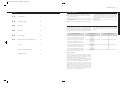
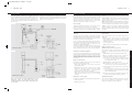
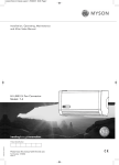
21522 Installation Manual V2 24/06/2011 11:06 Page 1
MYSON Eastern Avenue, Team Valley, Gateshead, Tyne & Wear NE11 0PG
T: 0845 402 3434, F: 0191 491 7465, [email protected], www.myson.co.uk
Cliprail Zone Pack Installation Guide.
FLOORTEC
Underfloor Heating
heatingthroughinnovation.
01.04.2011
heatingthroughinnovation.
21522 Installation Manual V2 24/06/2011 11:06 Page 3
Cliprail Zone Pack
Contents
03
l The underfloor heating must be connected to a traditional
two pipe heating system.
l Carefully consider the manifold position so it is both near
the area(s) to be heated, and also easily connected to the
heating pipework.
2.0
General Description
03
3.0
Preparation
04
4.0
Installation
05
5.0
Post Screeding
06
l We recommend that the underfloor heating be connected as
2.0 General Description
The Cliprail Zone Pack consists of a MYSON FLOORTEC
Compact Underfloor Heating Control Unit that takes heat from
a normal heating system and distributes it into a screeded floor,
via manifolds and 17/2 PeX-a pipe. The installation instructions
Flow Temperature °C
40
6.0
Risk Assessment for Screed Application
07
45
General
07
50
55
Underfloor Heating Installation
07
COSHH Assessment
07
l If you are unsure of any of the above points, contact your
heating engineer.
for the MYSON FLOORTEC Compact Underfloor Heating
Control Unit are supplied in its box, and are not covered in
detail here.
Floor Covering
Outputs Watts/sq.m
ceramic
71
carpet / wood
46
thick carpet
39
ceramic
94
carpet / wood
61
thick carpet
52
ceramic
117
carpet / wood
76
thick carpet
65
ceramic
140
carpet / wood
91
thick carpet
78
Important Notes
These figures assume 200mm pipe spacings, a 75mm deep
screed, 8ºC difference between the 17/2 PeX-a underfloor
heating flow and return and an air temperature of 20ºC.
Calculated in accordance with BSEN 1254-:1997.
Care must be taken when using underfloor heating with floor
coverings, which may be affected by heat, such as wood or vinyl
products. Consult the flooring manufacturer for guidance.
The underfloor heating installer must ensure the heat
requirement of the area to be heated is within the potential
outputs detailed above. Supplementary heating may be
required if the heat requirement is in excess of the above
outputs, if the system is to be operated intermittently, or a swift
response time is required. MYSON is not responsible for
providing any form of temperature guarantee.
2.0
Do’s and Don’ts
a separate timed heating zone. This may require an
additional timer and zone valve, which are not supplied.
Should it be connected into an existing heating zone,
consideration must be given to the response time of the
heating system.
1.0
1.0 Do’s and Don’ts
Plan the installation carefully, and consider the following:
1.0
03
21522 Installation Manual V2 24/06/2011 11:06 Page 5
Cliprail Zone Pack
Cliprail Zone Pack
4.0 Installation
Single-Zone
Fig. 1
The tails of return pipework are then cut to length and
connected to the return manifold (which contains the pressure
gauge). All pipework is fed to the manifold using pre-formed
pipe bend supports to ensure no creasing occurs during
transition from horizontal to vertical alignment. The pipework is
inserted into manifold ports and secured using brass
compression ring manifold connectors. The underfloor heating
layout is designed such as to have no joints other than the
connections at the manifold.
Prior to the screed being laid, the underfloor heating pipework
should be filled with water and tested to a pressure of 3 bar
gauge. The area under full test is to be protected from site
personnel during the test period. This pressure should be
maintained for a minimum of 2 hours and then reduced to a
working pressure of 1 bar gauge in accordance with current
H&S requirements. This should then be held during concreting
to ensure any damage resulting in a leak is identified
immediately. Once concreting is completed, the pressure may
be released.
Following curing of the screed, the underfloor heating system
can be filled with water, turned on and the flow temperatures
slowly elevated in accordance with our recommendations.
4.0 Installation
1. Border Edge Strip
l MYSON FLOORTEC Border Insulation (Part No. 50220) is
placed around the perimeter of the room. It may be fixed to
the walls by nails or clips positioned above the screed level.
Care must be taken to ensure any damp proof membrane
in the wall is not perforated. The polythene skirt of the
Border insulation must be lifted and placed over the floor
insulation prior to the screed being laid.
2. Insulation
l It is the responsibility of the builder to ensure the floor
insulation to which the Cliprail is fitted complies with
the Building Regulations. The insulation must be securely
fitted and taped before screeding. The required insulation is
not supplied by MYSON FLOORTEC.
3. Loop Layouts/Coil Cuts
l Survey the area to be used and carefully plan the heating
loop configuration. underfloor heating pipework is supplied
in 120m and 240m rolls for the 20m2 and 40m2 packs,
respectfully. One pipe loop is generally acceptable for an
area of up to 20m2, and two pipe loops should be used for
areas between 20m2 and 40m2. If two loops are utilised, it is
important that both loops lengths are equal.
6. PeX-a Pipe; Coupling Set
l Gradually complete the layout of piping according to the
required configuration. Final pipe run should be returned to
the opposing flow or return connection as in (5) above.
PRESSURE GAUGE
RETURN MANIFOLD
l PeX-a pipe is marked in metre lengths.
l Note the pipe length marking at both flow and return
connections and record the length of each loop to ensure
the pipe in economically utilised.
PUMP
l This must be attached to the wall with the heating flow and
return isolating valves facing downwards. The mini-manifolds
are connected to control unit with the flow manifold
(containing the air vent) to the pump outlet, and the return
manifold (containing the pressure gauge) to the appropriate
return connection. The pipe couplings and pressure gauge
are supplied with the mini-manifolds. PTFE or a similar
jointing compound should be used in making all
connections.
17mm PeX-a Pipe; Coupling Set
Note: PeX-a pipe cannot be installed when ambient
temperature is below freezing.
l Attach the end of the pipe coil to the flow or return port of
the manifold using the coupling set. The coupling set is
made up of a nut, pipe insert and split olive. The nut is
slipped over the pipe, the insert is then pushed into the end
of the pipe and the split olive is used as a compression ring
for the fitting. Take care not to over tighten. PTFE or a
similar jointing compound may be used in making the
fittings. Set the pump speed to 2 for a single loop system
with a floor area of up to 20m2 and to 3 for a two loop
system with a floor area between 20m2 and 40m2.
8. Complete Steps 4 to 8 for Each Loop
9. Filling, Venting and Pressure Test
l Attach a temporary mains water connection to the flow (red)
connection on the MYSON Underfloor Heating Compact
FLOW FROM PRIMARY
HEATING CIRCUIT
MIXING VALVE
RETURN TO PRIMARY
HEATING CIRCUIT
l If only one heating loop is used, cap off the second loose
connection with the supplied fitting.
5. PeX-a Pipe; Cliprail
4. MYSON FLOORTEC Underfloor Heating Compact
Control Unit
7. PeX-a Pipe Length
l Carefully remove protective strip along the underside of
Cliprail and fit to the insulated floor as required.
Align Cliprail to securely grip the pipework and facilitate a
uniform floor coverage.
l Prove adhesion. Provide additional fixing of Cliprail by
securing each end using special plastic Cliprail pins.
Continue to butt-joint Cliprails in accordance with pipe
configuration requirements.
l Holding the pipe coil in both arms walk backwards away
from the manifold, turning the coil whilst playing out the
pipe.
l Walk along the pipe and ensure piping is spaced according
to the design drawing requirements. Insert the pipe into the
pre-formed slots of the Cliprail, ensuring “snap fit”.
Insert the pipe into Cliprail at the following spacings:
(a) Straight runs - 1 per 3 metres
(b) Bends - 1 at 300mm from bend
The maximum bend radius for PeX-a pipe is 8 x pipe
diameter i.e. 17 x 2mm pipe - 136mm radius
l Additional “Anchor Clips” are provided to secure the pipe
during changes of direction. These red clips are screwed into
the insulation and provide a robust fixing where required.
Control Unit, and connect a temporary drain connection to
the return (blue) connection. Open the isolating valves and
allow mains pressure water to enter the system. Run water
through the system until the drain water contains no air.
3.0
Manifold
FLOW MANIFOLD
MANUAL AIR VENT
l Close the return isolating valve and allow mains pressure to
raise the water pressure of the underfloor heating system to
3 bar. If the mains water pressure is inadequate, a separate
hydraulic pump may be utilised.
l Close both isolating valves and leave the system pressure at
3 bar for 30 minutes. Check for any leaks and rectify if
necessary. Once system integrity has been proven, reduce
the pressure to 1 bar and prepare for screeding.
4.0
Plan the pipe route carefully to ensure each heating loop does
not exceed 120m in length. A basic typical pipe layout
is shown below. See Figure 1.
l Black pipe bend supports are placed where the pipe
direction changes from horizontal to vertical, under the
manifolds. These supports are designed to relieve stress on
the manifold connections and must be fitted.
LOOP 2 FLOW
Underfloor heating pipework is much easier to handle when
warm. If possible store the pipework in a heated room
for 24 hours prior to installation. Do not install underfloor
heating in temperatures below 0ºC.
The two-port manifold is installed at a convenient location in,
or near the area to be heated. The heating pipework is
connected to the flow manifold (which contains the air vent)
and then laid out in the required configuration. Pipes are held
in place with a clip rail system, which is fixed with self-adhesive
strips to a separation membrane (supplied and laid by others)
placed over the insulation (supplied and laid by others).
LOOP 1 RETURN
Ensure that the surface of the concrete slab onto which the
system is to be laid is both clean and dry and the area
is cordoned off to prevent unauthorised access.
05
(continued...)
LOOP 2 RETURN
3.0 Preparation
LOOP 1 FLOW
04
21522 Installation Manual V2 24/06/2011 11:06 Page 7
06
Cliprail Zone Pack
Cliprail Zone Pack
5.0 Post Screeding
4.1 Zone Value
All wiring should be undertaken by a qualified installer and
conform to IEE regulations. To comply with IEE regulations the
pump on the unit is provided with an earth connection via the
connection box. A fused spur should be provided adjacent to
the unit. The mains cable should be connected to the spur and
fused at 3 amps.
07
If fitting a room thermostat, fix in a position on the wall as
recommended in the manufacturer’s instructions. If a room
thermostat is fitted, remove the link between the terminals as
indicated on the wiring diagram.
The slab must be allowed to cure for a minimum of 21 days
before the heating system can be turned on. Following this
period the heating system should be allowed to reach
operating temperature by increasing the temperature 3ºC per
day from a commencing temperature of 30ºC until the final
operating temperature is reached. Failure to observe these
instructions could result in damage to the screed.
Floor Coverings
Underfloor heating doesn’t dictate to you in any way. It can be
used with almost any kind of flooring or floor covering.
There are four basic floor finish types which should be
considered: ceramic tiles, vinyl, timber and carpets. Ceramic
finished has the least thermal resistance with carpets having the
greatest.
Ceramic & Vinyl: Ceramic, plastic or vinyl flooring, have a low
thermal resistance, and will function very well with MYSON
underfloor heating systems.
Timber: Timber flooring is compatible with MYSON underfloor
heating systems however you must ensure that it is stored in
the room in which it is to be laid 2 weeks prior to installation.
Carpets: Carpets are generally compatible with MYSON
underfloor heating systems however heavy carpets with felt
underlay should be avoided as this may reduce the heat output
in the floor.
6.0 Risk Assessment for Screed Application
With Zone Value
Filling and Pressure Testing
Hydraulic Pressure Test to be Used on Site
Underfloor Heating Installation
The underfloor heating system should be filled with mains
potable water. A suitable hydraulic pressure pump may be
required.
Fitting of Control System
The manifold is made up and then fixed to a wall or temporary
structure using wall plugs and screws.
Tools: Power drill/cordless power drill, screw driver,
spanners/pipe wrench
Risk: With power tools there is always the risk of ‘flying
chips’. Due to the exposed nature of some sites and the
presence of other trades there is an increased risk of
electrocution from trailing cables and the like.
Please note this will not provide independent time and
temperature control. We would always advise where
possible independent control should be achieved by means
of a zone valve.
Action: Operatives should be trained in manual handling.
Installation of MYSON FLOORTEC underfloor heating systems
do not significantly add to these risks and normally applied
safety actions by other contractors on site should be satisfactory.
The following is a detailed examination of each stage of the
installation of MYSON underfloor heating. MYSON underfloor
heating method statements are used as a reference (copies
available from MYSON). Risks associated with each stage of the
installation are detailed and the appropriate actions to limit any
risk are given.
Without Zone Value
Risk: Pipe coils are heavy and must be considered under
manual handling. Coils are available in 120m and 240m
lengths. Both the 120m and 240m can be utilised without
mechanical assistance.
No other significant risks.
Action: Safety glasses are to be worn whilst drilling issued
under PPE. See electrical section for use of electrical
equipment.
Tools: Hydraulic pressure pump, Spanners/Pipe wrench.
Risk: Use of hydraulic pressure tests has a medium risk,
however the following procedure must be followed:
(i)
Ensure the area to be tested is cordoned off and that
no other site personnel are able to readily access the
area signage to be erected.
(ii) Whilst filling the system check for leaks.
(iii) Gradually raise the pressure to a maximum 3bar.
Check for leaks at all joints and mechanical fittings.
(iv) Re-check that all other site personnel are kept clear of
the test area.
(v) Leave pressurised for 2 hours to check for leaks. There
may be a small drop in pressure initially due to the pipe
work relaxing/temperature
(vi) After 2 hours the pressure should be released to 1 bar
gauge, which should be held during concreting.
Fitting Pipe to Control System
COSHH Assessment
Pipework is cut and fitted to the manifold using a mechanical joint.
The installation of MYSON underfloor heating does not involve
the use of any substances as defined by the ‘Control of
Substances Hazardous to Health’ regulations.
Tools: Pipe cutters.
Risk: No significant risk.
4.0
The use of hard hats, high visibility jackets and safety boots is
normal practice for all installation operatives. Where necessary,
ear protection and goggles will be worn during the use of
certain items of plant and equipment.
Pipe is decoiled and fixed to the insulation by means of a
plastic clip.
5.0
Construction sites have a number of general risks associated
with them and these should be detailed in the main contractors
site Health and Safety policy or Risk Assessment. Any special
risks with a particular site should highlighted.
Laying of Pipe
6.0
General