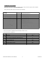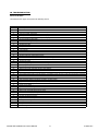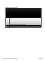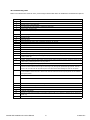
1
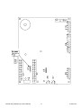
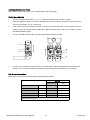
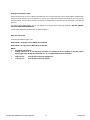
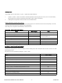
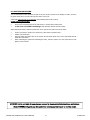
Strebel Condensing Water Heater Range
Installation & Service Instructions
CE 0063/2006
080606-500
Strebel WG Installation & Service Manual
210806 doc
STREBEL Ltd is not liable for any damage caused by inaccurately following these instructions.
Only STREBEL Ltd parts may be used when carrying out any repair or service works.
INDEX ......................................................................................................................................................................................2
SAFETY GUIDELINES...................................................................................................................................................................3
1.1
General guidelines............................................................................................................................................................3
1.3
Health and safety regulations 1993
1.4
Legionella
2.1
Special Precautions.......................................................................................................................................................4
Unpacking.......................................................................................................................................................................5
3.1
3.2
Mounting Position
4.1
Technical Data .................................................................................................................................................................................................6
5
6
6.2
6.3
7.
7.1
7.2
7.3
7.4
7.5
7.6
7.7
8.
8.1
8.1.1
8.2
8.2.1
8.2.2
8.2.3
8.3
8.4
8.5
8.6
8.6.1
9.
10.
10.1
10.2
10.2.1
10.3
10.4
10.5
11
11.1
11.2
11.3
12.
12.1
13.
13.1
13.2
13.3
14.
15
16
17
18
19
20
21
22
Front View......................................................................................................................................................................7
Combination Supplied........................................................................................................................................................................................8
Operation.
Description of the Hot water System
Modulation......................................................................................................................................................................9
Water Quality
T & P Valve....................................................................................................................................................................10
Condensed water drain...................................................................................................................................................11
Water connections
On/off pump..................................................................................................................................................................12
Cooling of the Boiler
Frost protection
Flue Systems.................................................................................................................................................................13
General
Maximum Flue lengths parallel.........................................................................................................................................................................14
Flue terminal positions
Air in and Outlet.............................................................................................................................................................15
Parallel Air in- and Outlet................................................................................................................................................15
Co axial flue maximum lengths.........................................................................................................................................16
Flue Capability...........................................................................................................................................................17
The air inlet and flue gas outlet system
The impact of the outlet to the load
WG resistance table
Example calculation
..................................................................................................................................................18
Lock Out/Run................................................................................................................................................................19
Electrical
Connector strip!
Phase sensitivity.............................................................................................................................................................20
Sensors ..........................................................................................................................................................................20
Fuses
Electrical circuit diagram.................................................................................................................................................21
PCB with plug numbers...................................................................................................................................................22
Control Panel..................................................................................................................................................................23
Settings
Sensors........................ ................................................................................................................................................24
Display codes.................................................................................................................................................................25
Starting the boiler..........................................................................................................................................................26
Putting into operation the first time.................................................................................................................................27
Adjusting and setting the output.....................................................................................................................................28
Setting the Maximum Output...........................................................................................................................................28
Setting the minimum Output...........................................................................................................................................29
Gas conversion......................................................................................................................................................... ...29
Inspection and Maintenance............................................................................................................................................30.
Display Codes.................................................................................................................................................................31
Long Term Shutdown......................................................................................................................................................32
Lock out User Complaint..................................................................................................................................................33
Troubleshooting..............................................................................................................................................................34
Causes of faults............................................................................................................................................................. 35
Troubleshooting Table.....................................................................................................................................................36
Remedies.......................................................................................................................................................................37
Maintenance...................................................................................................................................................................38
Strebel WG Installation & Service Manual
2
210806 doc
1. SAFETY GUIDELINES
1.1 - General guidelines:
Read all these instructions before commencing installation.
This appliance is free from any asbestos material.
It is the law that all gas appliances and fittings are installed by a competent person ( such as a CORGI registrant installer ) and in
accordance with the Gas Safety ( I nstallation and Use Regulations) , the relevant British standards for installation, codes of practice or rules
on force and in accordance with the Manufacturers ’ instructions.
The installation shall also be carried out in accordance with the following regulations, codes and standards:
1.2 - British Standards and codes of practice
•
•
•
•
The Building Regulations issued by the Department of the Environment.
The Building Standards ( Scotland ) ( Consolidation ) Regulations issued by the Scottish Development Department.
The Local Building Regulations and Local water by-laws, the gas services area and the Local Authority recommendations.
Wiring to the appliance must be in accordance with the IEE ( BS 7671 ) Wiring Regulations the Health and Safety Document No 635
“ T he Electricity at Work Regulations 1989 ” and any local regulations that apply.
•
•
•
•
•
•
•
•
Relevant British standards insofar as the relevant areas that are not covered by these instructions.
CP 342: Part 2, 1994. Code of practice for centralised hot water supply – buildings other than individual dwellings.
British Gas Publications: IM/2 purging procedures, IM/5 soundness testing, IM/11, IM/16 Installation of gas pipe work and boosters.
HSE guidance note PM 5, automatically controlled steam and hot water boilers.
CIBSE, IHVE, Guide ports A, B and C.
IGE/UP/10, IGE/UP/2 and IGE/UP/7.
IGE/UP/2 Gas installation pipe work and compressors or industrial and commercial premises
LPGA Code of practice 7:
Storage of full and empty LPG cylinders and cartridges. Highly Flammable Liquids and liquid Petroleum
gases Regulations 1972
•
BS 5440: Parts 1 and 2 ( Flues and Ventilation ) .
Part 1: Specifications for installation of flues
Part 2: Specification for installation of ventilation for gas appliances.
•
•
•
•
•
•
BS 5546
Installation of gas hot water supplies for domestic purposes
BS 6644
Installation of gas fired water boilers of rated inputs between 60 kW and 2 mW
BS 6798
Specifications for installation of gas fired hot water boilers of rated input not exceeding 60 kW
BS 6880
Code of practice for low temperature hot water heating systems for output greater than 45 kW
BS 6891
Installation of low pressure gas pipework of up to 28mm in domestic premises
BS 7206
Specification for unvented hot water storage units and packages.
Failure to comply with these regulations could lead to prosecution and deem the warranty invalid. This appliance must be installed in
accordance with the rules in force and in particular in relation to flueing and ventilation.
1.3 - Health and safety regulations 1993
It is the duty of manufacturers and suppliers of products for at work to ensure, so far as is practicable, that such products are safe and
without risk to health when properly used and to make available to users, adequate information about their safe and proper operation.
Strebel products should only be used in the manner and purpose for which they were intended and in accordance with the instruction in this
manual. Although the appliances have been manufactured with consideration to safety, certain basic precautions specified in this manual
must be taken by the user.
1.4 - Legionella
Particularly in health care facilities where occupants are significantly more susceptible to infection, a outbreak of Legionnaires ’ Disease,
have been associated with water systems in buildings.
A Code of Practice for the Control of Legionella in Health Care premises has been issued by the Department of Health ( 1991 ) .
Also Codes of Practice to other premises have been published: ( H S ) ( G 70 ) and ( C IBSE, TM13) .
The design and operation of water systems with reference to avoid of factors that favour colonisation by Legionella, including stagnation,
lukewarm conditions ( 20°C to 45°C ) and the accumulation of debris, scale and corrosion in the base of tanks and calorifiers.
Strebel WG Installation & Service Manual
3
210806 doc
2.1 Special Precautions
Take Care: The quality of the potable water should not exceed a hardness of 25°D
Take Care: Do not use Aluminium Flue gas tubes. Condense runs towards the boiler outlet, use extra
condense traps and siphons. Use stainless steel or plastic ( PP) f lues
Take Care: The boiler is used in combination with a hot water tank without any other heat exchanger; the tank
should be equipped with a T&P relief valve.
Take Care: The connection for a Remote DHW Stat is based on a OpenTherm Bus system ( s pecial Control
from Strebel) or an On/Off timer.
Take Care: After installation, the built in Air Vent must be opened.
Local regulations apply and must be adhered to along with the following•
Only an approved installer is allowed to install an “ u nvented ” system.
•
A Mains Unvented Kit for sealed Systems is required
•
A expansion vessel is needed for this installation; The maximum working pressure ( test pressure ) of the
system should not exceed 10 bar.
•
A Temperature and Pressure safety valve ( T&P valve ) of sufficient size with a opening Temperature of
100°C and a pressure of 10 bar is installed on the top of the tank: a adequate tube, including a tundish
has to be installed by the installer.
Strebel WG Installation & Service Manual
4
210806 doc
INSTALLATION of the STREBEL WG
3.1- Unpacking
Unpack and check all items delivered immediately upon delivery and report any shortages or damage. Re pack
all items for protection until installation is required.
The Strebel WG comes with the following documents and accessories
1x Installation & Servicing Instructions ” for the installer;
2x spare fuses and 3x spare nuts for mounting the burner plate ( attached to the front of the gas valve ) ;
1x dirt catcher siphon with nut and gasket;
On delivery, immediately unpack and check that the Strebel WG is complete and without any defects. Report
any damage immediately to Strebel Ltd. Re pack the goods for save keeping until installed
Important: Strebel WG boilers are set for natural gas group G20.
3.2 - Select the mounting position in the building
Installation must be carried out in accordance with Gas safety Regulations 1998, Building Regulations, the
Supply Regulations 1999 and the requirements of the local Gas Authority, Water and Fire Authorities and the
current B.S. and Codes of Practice listed in chapter 1.1.
•
A gas isolation valve should be installed in the room where the Strebel WG unit is to be installed.
•
The water heater should not be installed in a location that contains a bed, shower or bath.
•
Either side of the boiler must leave at least 20 mm empty space to walls or wall units.
•
The water heater must be located in a area where leakage from the tank and or water pipes and
connections, safety valves and drains, will not result in damage to the surrounding area. When such a
location is not possible, suitable precautions must be taken.
•
Access must be provided to the front of the water heater, approx. 50 cm.
•
There must be sufficient space to the side of the unit for installing the pipework.
•
There is no requirement for space either side of the unit for maintenance and service. This also applies to
space at the rear of the unit; the appliance can be placed against a wall.
The installation area must have the following provisions:
•
1 Wall socket with earth connection.
•
Connection to the sewer system for draining the unit and removal of condensation.
Other matters to consider when deciding on the location of the Strebel WG Unit:
•
The flue will be required to be terminated outside via a suitable wall or roof terminal.
•
The installation area must be dry and frost-free.
•
The WG Range incorporates a built-in fan. This fan does produce noise, depending on the demand on the
unit. Customers are advised to locate the unit in an area where noise emission does not caused any
disturbance. In this respect, Strebel Ltd advises mounting the unit on a solid concrete base or similar.
Strebel WG Installation & Service Manual
5
210806 doc
2.Technical Data - Strebel WG Condensing Water Heater Range.
Table 1 - Technical Data WG
S-WG Water Heater - Technical Data Table
General
Product Identification Number
Dimensions (h x w x d)
CE 0063 BR3190
835 x 458 x 485
mm
Classification
890 x 458 x 670
II2H3P
Gas Appliance Type
B23; C13X,C23X,C33X,C43X, C53X, C63X,C83X
Type Boiler
WG 80
WG 100
WG 120
WG 150
WG 180
5
6.5
8.3
10.4
12.9
Kg
67
71
77
84
93
In- and outlet water connection (union)
inch
1 1/2”
2”
2”
2”
2”
Gas connection
inch
R ¾”
R ¾”
R ¾”
R 1”
R 1”
Flue duct flue/air inlet concentric**
mm
80/125
100/150
100/150
100/150
100/150
Power consumption
Watt
170
170
170
250
250
IP40
IP40
IP40
IP40
IP40
Water content etc.
Weight (empty)
Litre
Protection class
Hot water supply
Nominal input (Net) 80/60ºC
kW
15-74.3
17.2-92.2
22-111.2
20-138
25-166
Nominal input (Gross) 80/60ºC
kW
16-82
19-102
24-124
22-153
28-184
m³/hr
7.9
9.8
11.8
14.7
17.6
Gas flow max. (G20)
Efficiency at 80/60ºC High Fire
%
95
95
95
96
96
Efficiency 50/30ºC Low Fire
%
109
109
109.5
109.5
109.5
Nominal output at 80/60ºC
kW
70.8
87.6
106
132
160
Nominal output at 50/30ºC
kW
16-78
19-97
24-116
20-144
27-175
NO x emission
mg/kWh
<15
<15
<15
<15
<15
CO emission
mg/kWh
<20
<20
<20
<20
<20
1.5
1.0
Technical details
CO2- flue gas
%
8.8
Dew point combustion gas
°C
≈ 53
Temp. Flue gas by ambient temp 20ºC
°C
≈ 80
Available pressure for the Flue system*
Pa
200*
PH value condensate
pH
4 to 5.5
Available DHW pump pressure for the installation
Head
2.5
[mWC]
2.5
3.0
Max. outlet temp.
°C
80
Pressure DHW-system min./max.
bar
1.0 – 10
* At this resistance level, the boiler remains within the value of the boiler label.
** In the case of higher flue resistances, the fan pressure will drop. Further information on Page 12.
Strebel WG Installation & Service Manual
6
210806 doc
S-WG Water Heater - Technical Data Table
Dimensional Data Table
150 Litre
230 Litre
320 Litre
450 Litre
750 Litre
Dimension
Cylinder Diameter
A
510
605
605
735
950
Cylinder Height
B
1390
1430
175
1645
1850
Thermometer Connection
C
1065
1125
1410
1230
1400
Cold Mains Feed
D
250
250
250
300
345
Hot Water Outlet
E
See separate individual cylinder data sheet for specific dimensions
T&P Valve Connection
F
See separate individual cylinder data sheet for specific dimensions
Return to Water Heater
G
250
250
Flow from Water Heater
H
55
55
Frame Height
J
1570
Frame Width
K
550
Frame Depth
L
530
Frame Leg Height
M
760
Water Heater
Height
N
Width
P
Depth
Q
250
300
345
60
60
60
S-WG 80
S-WG 100
S-WG 120
S-WG150
S-WG180
835
835
835
889
889
485
485
676
676
458
485
Please note: More specific dimensions relating to the water heater & cylinder are available on separate data sheets
Strebel WG Installation & Service Manual
7
210806 doc
6.2
-
Cylinder Connections / Dimensions
Cylinder Size (Litres)
150
230
320
Connections to the Water Heater
Male
1 1/2"
1 1/2"
2"
Cold inlet / Hot outlet
Male
1 1/2"
1 1/2"
2"
T&P Valve Tapping
Female
Circulation connection
Male
3/4"
3/4"
3/4"
Thermometer connection
Female
1/2"
1/2"
1/2"
Height
mm
1390
1430
1750
Diameter
mm
510
605
605
Strebel WG Installation & Service Manual
8
450
2"
2"
750
2"
2"
3/4"
1/2"
1645
735
3/4"
1/2"
1850
950
210806 doc
Operation of the Strebel boiler
The domestic hot water boilers from the STREBEL series are Direct Fired Hot Water boilers with maximum high
efficiency. Such performance can be reached by, among other things, using a special heat exchanger made of
stainless steel. The heat exchanger allows flue gases to cool down below condensation point, condensing the flue
gases and releasing extra heat. This has an immediate positive impact on the efficiency, exceeding 100%:
6.3- Description of the Hot Water System
The water heater works according to the loading principle: the mounted pump( s ) on the flow pipe of the boiler,
directly pumps the domestic water out of the bottom of the tank. The water is heated up by the boiler, and is carried
back to the bottom of the tank. During hot water draw off from the tank, cold water enters the tank at the bottom,
directly opposite the flow pipe of the boiler, this cold water and a proportion ( depending on draw off ) of the water
from the tank is mixed inside the tank, then fed into the inlet of the boiler. The inlet temperature of the boiler is variable: the more water that is drawn off, the lower the inlet water temperature will be.
The outlet water temperature of the boiler, which is sent to the tank, has a temperature sufficient for maintaining the
outlet temperature of the tank constantly at the set hot water temperature. The boilers ’ burner modulates on the
basis of the hot water outlet temperature of the tank and when no water is drawn off , the boiler modulates on the
basis of the water temperature inside the tank, until the set water temperature has been reached. During draw off,
the inlet temperature is as low as possible therefore the boiler can condense giving an efficiency of over 105% .. A
safety control stops the boiler firing, when the water volume through the boiler creates a higher than 17K delta T.
Strebel WG Installation & Service Manual
9
210806 doc
7.1 - Water quality and treatment
In hard water areas scaling of the heat exchanger of the boiler and also in the outlet pipes from the boiler to the
tank can occur and therefore the control of the boiler is equipped with a sensor to help prevent scaling up, which
could lead to Boiler damage. This sensor activates a service code in the display showing that the system has to
be cleaned or flushed with chemicals.
Water treatment is normally not recommended up to a water hardness of 300ppm ( 20 degrees Clark ) , because
the boiler has a control system for the heat exchanger, which reduces this scaling up effect.
It is advisable, to drain the system once every 12 months, to take away the debris at the bottom of the tank.
With water hardness of over 300ppm, the risk of scaling up can be minimised by reducing the water temperature
setting to less than 55°C or by fitting suitable water treatment equipment .
Strebel WG Installation & Service Manual
10
210806 doc
7.3 - Condense water drain
The condensed water drain is in the centre at the bottom of the boiler and has a ¾
inch hose discharge. Connect this flexible hose to the sewer system., by means of
a tundish.
Important:
Use only plastic parts with the condensed water drain. metal lines are not allowed.
Tip!
Blockage of this drain may cause damage to the boiler. The drain connection is
correct when the condensed water can be seen flowing away, e.g. using a funnel.
Any damage that may occur is not covered by the warranty of the Strebel WG
Unit.
7.4 - Water connection
•
The cold-water connection ( 1 ½ ” ID) is to be found at the bottom rear of the tank, while the hot water
connection ( 1 ½ ” ID ) is situated at the top of the tank.
•
A circulation connection ( 3/4 ” OD ) is placed at the right hand side of the tank ( app. 30 cm from the
floor )
•
A connection is available for a thermometer ( 1/2 ” ID) at the topside ( remove plug ) of the cylinder
•
To prevent heat losses of the system, there is a built-in non-return valve in the return connection to the
boiler.
•
To prevent contamination of the Strebel WG heat exchanger, fully rinsing the system with clean running
water prior to first use, is required.
Strebel WG Installation & Service Manual
11
210806 doc
7.5 - On/off pump
•
The on/off pump ( s ) has a speed regulator adjusted to the highest setting: Do not change this setting!
•
The boiler control is equipped with a safety device for controlling the volume of the pump: when the volume
measured does not match with the safety setting, the display will show a blocking of the boiler: after 4
blockings, there will be displayed a Lock Out signal.
•
After pressing the Reset button, the boiler starts to work again, but now at 50% of its output: please call
your installer in this case. !!
•
The Strebel WG control has a built-in pump switch with a standard 1-minute overrun.
•
The pump will work at top speed when heat is required. When heat is no longer required, the pump will
continue to run for another 1 minute before it stops. The pump for the tank is also activated for one minute
every 24 hours. The 24-hour cycle starts as soon as the power supply to the boiler is activated.
7.6 - Cooling of the Boiler
To prevent scaling of the boiler, the fan in the boiler has a post running time exceeding the over-run time of the
pump: the post running time of the fan is variable depending on the water temperature in the heat exchanger.
7.7 - Frost protection
The boiler has a built-in frost protection, automatically activating the pump when the boiler inlet water
temperature drops below 5°C. When the boiler water temperature comes subsequently down to 3°C, the burner
is ignited. This will stop as soon as the water temperature has reached 10°C.
The above-mentioned temperatures relates to the temperature measured with the INLET sensor of the boiler
Strebel WG Installation & Service Manual
12
210806 doc
8. Flue Systems
8.1 - General
Flue systems must be installed in accordance with the Clean Air Act, ( Consult your Local
Authority for guidance and their interpretation ) to ensure the products of combustion are
properly dispersed.
In the following chapters the drawings show the minimum clearances .
Important!
Because flue gases have a low temperature ( below 80°C ) the boiler needs to have a
high efficiency stainless steel or plastic flue system suitable for condensing boilers
Pos.1
Coaxial Flue Extension Piece
Pos.2
Flat Roof Flashing
Pos.3
Coaxial Roof Terminal
Pos.4
Pitched Roof Flashing
Pos.5
Coaxial 90° Bend
Pos.6
Coaxial Wall Terminal
Pos.7
Coaxial Flue Connection with condense drain point.
Maximum Flue Lengths for Coaxial Flue Configuration Flues must be installed to current regulations
35
55
Diameter ( A, B, C )
80/125
80/125
Max Length ( A, B )
45 m
22 m
44 m
21 m
Max Length ( C )
Material
Strebel WG Installation & Service Manual
Plastic or Stainless steel with Condense Drain Connection
13
210806 doc
Maximum Flue Lengths for Parallel Flue Configuration.
Flues must be installed to current regulations
35
55
Diameter ( D, E, F )
80-80
80-80
Max Length ( D )
60 m
25 m
Max Length ( E )
35 m
15 m
Max Length ( F )
33 m
13 m
Material
Plastic, Stainless steel with a Condense waste tube
( n o air inlet )
Strebel WG Installation & Service Manual
14
210806 doc
8.2.2 - Parallel Flue Configuration ( Separate Air Supply and Exhaust )
Pitched Roof & Horizontal Termination
E
F
D
Pos.1
Parallel Flue Extension Piece
Pos.7
Parallel Air Inlet Wall Terminal
Pos.2
Pitched Roof Flashing
Pos.8
Weathering Cowl
Pos.3
Parallel Flue Gas Roof Terminal
Pos.9
Ventilation grill
Pos.4
Parallel Air inlet Roof Terminal
Pos.10
Parallel Flue Connection with condense
Pos.5
Parallel 90° Bend
Pos.6
Parallel Flue Gas Wall Terminal
Strebel WG Installation & Service Manual
drain point.
15
210806 doc
Maximum Flue Lengths for co-axial Flue Configuration.
Flues must be installed to current regulations
8.2.3
35
55
Diameter ( G, H)
80/125
80/125
Max Length ( G )
45 m
22 m
Max Length ( H )
44 m
21 m
Material
Strebel WG Installation & Service Manual
Plastic or Stainless steel
16
210806 doc
8.3 - Flue Capability
The WG boiler has an excess pressure combustion system using a concentric flue arrangement of 80 mm within
a 125 mm air tube over considerable distances. All the boilers can be transferred to parallel tubes.
8.4 - The air inlet and flue gas outlet system.
kW
The available pressure for the inlet and outlet system is 200
Pa, without the output
55
decreasing. The graph to the left
shows the reduction of kW output as the flue resistance
WG55
increases over 200 Pa.
50
N.B.!
Install the horizontal parts under 1% fall in the direction of
45
the boiler ( o ne centimetre for every linear meter ) . Failing
to do so may result in water from the condensation building
40
up in the flue gas tube. In turn, this may cause failure.
35
8.5 - The impact of the outlet to the load
WG35
The table on the left shows the relation between the load
30
0
100
200
300
400
500
and the resistance of the inlet and the outlet of the system.
600
Pa
8.6 - WG resistance table
The load of the boiler is affected by the resistance of the air inlet and outlet system as a result of gas/air coupling
in the controls of the boiler. At a resistance up to 200 Pa for the WG35 and WG55, the load will be as indicated
on the Identification Plate of the boiler.
Flue Components - Resistance Table
Resistance inlet and outlet system [Pa]
Item
Boiler
( mm )
WG 35/230
WG55/230
roof terminal
125/80
6
6
13
outside wall terminal
125/80
6
6
13
straight tube/m
125/80
2
2
10
45° bend conc.
125/80
1
1
5
90° bend conc.
125/80
2
2
10
straight tube/m
80
3
3
4,1
45° bend
80
1,5
1,5
2,1
90° bend
80
3
3
4,1
Flue gas
straight tube/m
80
4
4
5,3
discharge
45° bend
80
2
2
2,7
90° bend
80
4
4
5,3
Terminals
Concentric
Air supply
WG35/150
N.B - Example of how to use these resistances shown on Page 18.
Strebel WG Installation & Service Manual
17
210806 doc
8.61 - Example calculation
Boiler type: WG 55
Coaxial Flue System: 80/125
Length of flue run from the boiler to the roof terminal: 25 meter
No. of 90° Bends required for the installation: 4 pc.
Calculation:
90°Bends: 4 pieces.
4 x 10
=
40 Pa
45° Bends: 2 pieces
2x5
=
10 Pa
Straight tube: 10 m.
10 x 10
=
100 Pa
Roof terminal
=
13 Pa
Total Resistance of Flue Components
=
163 Pa
In this case, the total resistance of the flue components does not exceed 200 Pa. This means that the output
of the unit will not be affected by the flue resistance.
Strebel WG Installation & Service Manual
18
210806 doc
11
Remote Fault
Through the use of a external power ( e.g. 230 VAC ) , this Volt Free contact closes in Lock Out.
12
Control LO
condition
E.g. a lamp or a buzzer can be connected ( Relays are build in the boiler control ) .
Parameter: No change in Parameter required when connected
13
Remote
Through the use of a external power ( e.g. 230 VAC ) , this Volt Free contact closes on Heat Demand.
14
signal for Heat
E.g a lamp or a buzzer can be connected ( Relays are build in ) .
demand.
Parameter: No change in Parameter required when connected
15
Pump
The pump ( s ) are factory connected
16
17
18
Pump is switched off, when there is no heat demand, after post running time.
Permanent Supply
The permanent supply is connected to these terminals, of which 19 is PE ( Ground)
19
The display has an ON / OFF button to switch the boiler on or off.. Isolate at power supply before
20
attempting any work. The electrical connections to the WG are made via discreet plugs and sockets, which
are located within the boiler case, on top of the control panel. Connections must only be made using
appropriate diameter multi strand flex cables and cable entry must only be via the rubber gland cable
points located at the bottom rear side of the appliance: the low voltage cables at the left side- and the 230
V cables at the right side of the boiler.
Strebel WG Installation & Service Manual
19
210806 doc
Phase sensitivity
The Strebel WG Water Heaters are not phase-sensitive.
Fuses
On the PCB. board, there are 4 fuses, of which only 1 can be replaced:
Fuse nr.
Used for
Value
F1
Ignition
Automatic reset
F2
Electronics
Automatic reset
F3
Electronics
Automatic reset
F4 - 230 VAC
Mains
3,15 AT
Sensors
The following temperature sensors have been fitted in the Strebel WG Units:
S1 = The outlet water sensor
( o n the front left of the heat exchanger)
( 1 0Kohm@25°C )
S2 = The inlet water sensor
( o n the back left of the heat exchanger)
( 1 0Kohm@25°C )
The sensors used in the Strebel WG Units are NTC type ( Negative Temperature Control ) and have the values
shown below:
Temperature
Resistance of Sensor
[°C]
1,& 2, [Ohm]
0
32550
5
25340
10
19870
15
15700
20
12490
25
10000
30
8059
35
6535
40
5330
45
4372
50
3605
55
2989
60
2490
65
2084
70
1753
75
1481
80
1256
85
1070
90
915
95
786
Strebel WG Installation & Service Manual
20
210806 doc
Strebel WG Installation & Service Manual
21
210806 doc
Strebel WG Installation & Service Manual
22
210806 doc
Control Panel Features:
Double pole On/Off Switch -
O - No Mains Power to the PCB - Off Position.
I - Mains Power activated - Unit is On.
Setting - Turning the dial labelled “ SETTING ” enables the Hot Water Temperature of the tank to be adjusted
and set. By turning this dial, the set temperature will be displayed.
When an outside sensor is connected, the Hot Water Temperature, set by the heating curve will be displayed.
This set Hot Water Temperature can be shifted within +10°C and -10°C using the SETTING dial.
Triple Digit Display - Always shows the set Hot Water Temperature, except when the unit is in No Demand Status
or Lockout/Fault Status.
Green LED Indicator ( Burner Firing LED )
- When the burner is On and ionisation is detected, the LED is illuminated.
- When there is no heat demand or no ionisation, the LED will not be illuminated.
RESET Button - When a code is flashing on the Triple Digit Display, there is a lockout situation. By pressing the
RESET button, the unit will begin ignition sequence again. Please make a note of the code on the display in order
to establish the reason for lockout.
SERVICE - Behind the plastic cap is a plug for interfacing with a Laptop Computer via an interface cable.
Connection to this, in conjunction with the appropriate software facilities, will enable the operational parameters
of the unit to be altered in the boiler control.
SERVICE Button - Below the SERVICE plug connection is a small button within a hole/recess which can be
pushed with a ballpoint pen. By pushing this button the unit will fire and the speed of the fan can be set by turning
the SETTING dial. The unit can be set back to automatic operation by pressing this button again.
Strebel WG Installation & Service Manual
23
210806 doc
Display console buttons
There are a couple of uses of the buttons and knobs on the display console, namely to adjust settings or to get information:
Symbol
--
Meaning
OFF
0
No Demand
On Demand, the required boiler temperature is shown on the Display.
Service Button
•
In order to set the gas-valve for the maximum output as well as for the minimum output, the appliance has to be put
into the SERVICE mode. Press a ballpoint pen (or similar) into the small hole beneath the plastic cap at the right side
of the control fascia (see page).
•
By turning the CH knob, the speed of the fan can be set between the maximum and minimum speed. The display will
show the speed of the fan e.g. 25 means 2500 rev/min.
•
After 10 min. the boiler switches back to the automatic program. If the setting of the gas-valve is not complete, press
the switch again.
•
The temperature of all the connected sensors can be shown (without the help of a laptop) on the display. Press the
RESET button, the first temperature is now shown (blinking) together with the code of the sensor (blinking).
To see the temperature of the next sensor, press again the RESET button.
Preparation for light up.
Fill the calorifier and the Boiler system using the appropriate filling method. The correct fill pressure is >1 bar, max. = 6 bar.
Pay attention to the following aspects in order to have a clean system:
•
•
Thoroughly power flush out the hot water system removing all traces of flux and debris.
Check the circuit for leaks and repair to prevent oxygen from entering the system.
The boiler has an automatic air vent (not fitted to the SCB 60), at the top of the boiler, this must be opened when the
boiler is put into operation. Check that the A/V screw cap is open by at least one twist. Manually vent the SCB60 using a vent
key. Check all system air vents are open.
Shortly after putting the boiler into operation, check the water pressure. Cure any leaks on the and DHW system.
Strebel WG Installation & Service Manual
24
210806 doc
Display codes
On the display, when no code is shown ( e .g. A3 ) , appears two possible indications:
Two digits on the display - This indicates the Set Value of the tank temperature.
•
When the green led is not illuminated there is no heat demand.
•
When the green led is illuminated, there is heat demand and the unit is active ( B urner firing )
A blinking dot at the bottom right of the display means - The Unit is incorrectly set for a “ cascade function ”
Display codes without illumination of the green LED ( B urner Firing )
When a code is displayed ( t he green LED is not illuminated ) it means that there is a heat demand, but the
boiler is temporarily out of order. This is commonly due to the temperature of the unit being higher than the set
temperature. After cooling down, the appliance will automatically start to function again.
Display Codes without Lockout Lamp Lit
Status
Code on display
Action
Outlet temperature too high
A2
Wait until temperature decreases
Speed of the fan is too high
A6
Wait until the speed is OK
Speed of the fan is too low
A7
Water-flow through boiler too low
A8
Wait till gradient is ok
Flame simulation
C1
Wait
High limit thermostat is active
C3
Wait for cooling down
Power limitation ( 5 0% ) after too many gradient blockings
E6
Call your installer
Error Codes - Lock Out Status
As the burner control goes into Lock Out, the display will show a blinking code, which corresponds
with the cause of the error; the table below shows the errors. The unit can only be reactivated by
pressing the RESET Button.
Status
Code on Display
Short Circuit in Ionisation Circuit
F0
Wrong Fan speed
F4
No Flame after 5 Ignition attempts
F5
Flame lost ( 4 times ) during Running
F6
Outlet sensor shorted or interrupted
E0
Inlet sensor short/interrupted
E2
Too many ( 3 times ) the water-flow through the boiler too low
E6
Parameter programmed
PP
Parameter incorrect programmed
PE
Burner control in not working correct
nc
Limit temperature or problems with the wiring to the gas valve.
H1
Strebel WG Installation & Service Manual
25
210806 doc
Starting the boiler
General
Measure the connection pressure in the gas pipe at the pressure nipple ( 3 ) of the gas valve. The minimum
connection pressure needed for the boiler to work properly under the correct load must be higher than 10mbar.
However the gas pressure must comply with current local regulations.
Installer program
Using the control facilities on the Control Panel, it is possible to set parameters and obtain information:
•
“ 0 ” on the display means: “ No heat Demand ”
•
On Heat Demand, the required ( Set ) water temperature is shown on the display
•
SERVICE button:
In order to set the gas valve for the maximum output as well as for the minimum output, the appliance has to
be put into the SERVICE mode. Press the SERVICE Button ( with a ballpoint pen ) beneath the plastic cap
at the right side of the display.
By adjusting the SETTING Dial, the speed of the fan can be set between the maximum and minimum Fan
speed.
The display will show the speed of the fan e.g. 25 means 2500 r/min.
After 10 minutes, the boiler switches back to the automatic program. If this occurs when the setting the gas
valve, press the SERVICE Button another time to continue making the required adjustments.
•
Without the help of a laptop, the temperature of all the connected sensors can be shown on the display. By
pressing the RESET button, the first temperature is shown ( blinking ) together with the code of the
sensor ( blinking ) .
•
To see the temperature of the next sensor, press the RESET button again.
FL
temperature
Flow temperature
rE
temperature
Return temperature
dH
temperature
Hot water temperature
cA
temperature
Temperature of the external Sensor
The Strebel WG Range has an automatic de-aerator on the top of the boiler. This must be opened when the
boiler is put into operation. N.B.! - Check that the screw cap has been turned loose at least one twist.
Putting the WG out of operation
Put the On / OFF switch in position “ O FF ” .
Drain the hot water boiler and the system in the event that the boiler is put out of operation during sub-zero
temperatures. Open the filling and drain valve of the hot water system and the boiler drain valve on the right-hand
side of the boiler.
Strebel WG Installation & Service Manual
26
210806 doc
Putting into operation for the first time
Once the system has been tested and everything is in order according to this manual, connect the mains
power and turn the boiler on, using the ON/OFF switch.
With the boiler turned on, the display will be showing the set water temperature.
The burner control will repeatedly give an electronic spark, for ignition, until a flame appears. If no flame
appears after several attempts, check that the gas valve has been set correctly.
Strebel WG Installation & Service Manual
27
210806 doc
Adjusting and setting the Output
When setting a gas control valve, set via measuring the CO₂ percentage.
Setting the combustion
•
The CO₂ should be set to 8.8% ( +/- 0.3 ) - measured without boiler front door in place.
•
Press the SERVICE Button and set the SETTING Dial to the maximum fan speed. The Fan speed is
shown on the display. e.g. 25 = 2500 r/min.
•
If the measuring process takes more than 10 minutes, the boiler will return to the automatic mode. If
required, press the Service button another time. When finished, wait for the full 10 minutes, or press
the SERVICE Button again.
•
Turn the SETTING Dial until the maximum RPM setting has been reached.
•
In order to set or adjust the maximum load, use screw [2] for making the adjustment to the maximum
setting. Turn the screw clockwise to decrease or anti-clockwise to increase the CO₂ percentage.
CO₂ % measuring method.
Adjust the CO₂ % for the maximum output according following table.
Gas type
Natural Gas G20
LPG
no
no
41.52
76.64
( M J/m³ )
34.00
88.00
CO2 max. output
(% )
8.8 ( +/-0.3 ) *
9.8 ( +/-0.3 ) *
CO2 min. output
(% )
8.5 ( +/-0.3 ) *
9.5 ( +/-0.3 ) *
Injector
Wobbe ( bw ) ( MJ/m³ )
Calorific Value net
* measured without boiler door
Strebel WG Installation & Service Manual
28
210806 doc
Setting the minimum output
Set the minimum load, once the maximum load has been set. In service mode turn the CH knob until the minimum RPM
setting has been reached (20 on the display). In order to set or adjust the minimum load, twist the screw [1] for the
minimum setting. Turn the screw clockwise to increase or anti-clockwise to decrease the CO₂ percentage, (see table 4a
page 30).
For S-CB150 and S-CB180 Boilers, you are only allowed to set the gas valve on the right hand side. DO NOT ADJUST
THE LEFT HAND SIDE GAS VALVE.
For Gas Valve Adjustment see illustration on page 29 Figure 4
8.6.6 Gas conversion
Converting from Natural gas to LPG:
Boilers with a single gas valve: WG 60 up to 120 kW:
Boilers with a two gas valves: WG 150 up to 180 kW:
NOTE:
•
•
Set LPG by CO emission
Setting LPG CO² % is not important, because it is influenced by the quality of the LPG, which
differs quite a lot. Mostly the measured CO² % is roughly between 9.5% and 10%.
•
•
High Fire CO:
Low Fire CO:
must be set to less than 100ppm CO.
must be set to less than 10ppm .
Strebel WG Installation & Service Manual
29
210806 doc
14 INSPECTION AND MAINTENANCE
General
The boiler requires inspection at least once every 12 months.
As a rule of thumb, inspection/maintenance is to be carried out also when the boiler generates a number of similar error
codes.
Major Service)
An inspection should cover at least the following matters.
a.
Ask the user about any problems with the CH boiler and/or any comments.
b.
Check the system (water pressure ) Minimum 1 bar
c.
Remove the casing of the boiler and check all lines and connections for traces of water and water leakage.
d.
Inspect the top of the casing and/or the top of the boiler for water leakage or traces of water from the air supply
pipe or the de-aerator.
e.
Open the condense siphon and remove any dirt.
f.
If a laptop computer is available, connect this computer and check the service page for error messages, starts and
failed / successful starting attempts.
g.
Fire the boiler on maximum output, and measure the output and the CO₂ percentage. (CO on LPG)
h.
Fire the boiler on minimum output, and measure the output and the CO₂ percentage. (CO on LPG)
i.
Note the noise of the CH pump and the fan.
j.
Dismantle the burner unit: remove the 6 x M6 nuts and the ignition cable, and move the burner unit forward. Remove the plug of the fan cable to the fan when the burner has been pulled half-way from the combustion chamber
Check the inside of the heat exchanger.
k.
Dismantle the air gas mixing box on the suction side of the fan and check the fan blades.
l.
Check the distance from the electrode to the burner; there should be 4 to 5 mm gap.
Fig.3. - Distance from electrode to S-CB burner.
Strebel WG Installation & Service Manual
30
210806 doc
15 Display Codes
On the display, when no code is shown ( e.g. A3) , appears two possible indications:
1.
A double “ numbers ” means: the Set Value of the tank temperature; when the green led is not lit ( t here is no heat demand ) ,
when the green led is lit, there is heat demand and the boiler is active ( flames on the burner )
2.
A blinking dot a the right bottom means: the boiler is set for cascade function
Display codes without the green LED lit ( Burner)
When a code is displayed, and the green LED is not lit, it means that there is a heat demand, but the boiler is temporarily out of order,
commonly, because the temperature is higher than the set temperature.
After cooling down, the appliance will automatically restart and function.
Status Codes - without Lockout lamp illuminated.
Status
Code on display
Action
Outlet temperature too high
A2
Wait until temperature is decreasing
Speed of the fan is too high
A6
Speed of the fan is too low
A7
Wait until the speed is OK
Water-flow through boiler too low
A8
Wait until gradient is ok
Flame simulation
C1
Wait
High limit thermostat is active
C3
Wait for cooling down
Power limitation ( 5 0% ) after too many gradient blockings
E6
Call your installer
Error Codes - Lockout Status with lamp illuminated
As the burner control goes into Lock Out, the display will show a blinking code, which corresponds with the cause of the error; the table
below shows the errors:
The boiler can only be re-activated by pressing the “ Reset ” button.
Status
Code on Display
Short Circuit in Ionisation Circuit
F0
Wrong Fan speed
F4
No Flame after 5 Ignition attempts
F5
Flame lost ( 4 times ) during Running
F6
Outlet sensor shorted or interrupted
E0
Inlet sensor short/interrupted
E2
Too many ( 3 times ) the water-flow through the boiler is too low
E6
Parameter programmed
PP
Parameter incorrect programmed
PE
Burner control in not working correctly
nc
Limit temperature or problems with the wiring to the gas valve.
H1
Strebel WG Installation & Service Manual
31
210806 doc
9. LONG TERM SHUTDOWN
It is recommended to leave the boiler turned on all year round to prevent frost damage in winter, and moving parts seizing due to corrosion during other times of the year.
If the boiler has to be put out of operation, the following action must be taken:
LONG TERM SHUTDOWN
•
Close the gas cock.
•
Remove the electrical plug from the wall socket, or switch off the mains-power.
•
In the event of possible frost damage: drain both the calorifier and the system.
When draining the boiler, drain the system first. Then open the two drain cocks of the boiler.
•
•
•
•
Put the O/I switch to position “O” and the On / OFF switch in position “OFF”.
Isolate at local isolation.
Open the filling and drain valve of the system and the boiler drain valve on the right-hand and lefthand side of the boiler.
When restarting the system and restarting the boiler, treat the system as a new system and its compliance to this manual.
STREBEL Ltd is not liable for any damage caused by inaccurately following these instructions.
Only STREBEL Ltd parts may be used when carrying out any repair or service works.
Strebel WG Installation & Service Manual
32
210806 doc
17 LOCK OUT / User Complaint
As the burner control goes into Lock Out, the display will show a code (see also 8.3 page 27) which corresponds
with the cause of the error. The table below shows the errors.
Only by pressing the “RESET” button can the boiler can be reactivated.
Meaning
Short Circuit in Ionisation Circuit
Limit Temperature
Wrong Fan speed
No Flame after 5 Ignition attempts
Flame lost (4 times) during running
Flow sensor shorted or interrupted
Return Sensor short/interrupted
New Parameters programmed correct
Parameters incorrectly programmed
Burner Control has malfunction
No communication (in cascade mode)
Burner defect
Code on
Display
F0
F2
F4
F5
F6
E0
E1
E2
E4
E5
PP
PE
nc
nc
H1
Possible cause of the Lock Out
See fault numbers Page 34 to 37
18; 35; 61
4;5;21;23;24;29;30;42;46
7;8;9;13;19;39;40;41
10;11;16;18;22;25;35;
10;12;16;22;25;26;32;44
4;5;23;29;46
3;4;21;24;25;38;43;55;
4;5;23;29;46
3;4;21;24;25;38;43;55;
1;2;3;4;21;24;30;43;46;51;55;63;
Press Re Set Button
Revise programme
Switch power off then on
Check cables to all boilers and Bus address numbers
Press reset button
There are several faults or complaints that the boiler display is unable to convey.
Some of these faults or complaints are:
a.
Complaint
The water is not warming up but the boiler is working
Cause of the fault (see page 34 to 37)
45;53;54
b.
Noisy ignition
c.
Burner of the boiler is continuously on, but the water is not warming up
d.
e.
f.
boiler is not firing
Burner of the boiler is continuously on; wateris getting too hot
Boiler is very noisy ( banging ) during operation
g.
Tops of radiators are insufficiently hot
h.
ON DHW, the water is cold
24;56
i.
Temperature of the DHW is far too hot
51;57
j.
ON DHW, the water remains below 60°C
51;58
k.
l.
16;35
55
ON DHW, the boiler is very noisy
23;59
Fault after replacement of the burner control
Strebel WG Installation & Service Manual
45
1;42;52
2
29;46;66
60
33
210806 doc
18. TROUBLESHOOTING
Cause of the fault
The faults listed on page 33 may have the following causes.
Cause No.
1
2
3
4
5
6
7
8
9
10
11
12
13
14
15
16
17
18
19
20
21
22
23
24
25
26
27
28
29
30
31
34
35
36
37
38
39
40
41
42
43
44
45
Cause List
incorrectly connected.
short-circuit in cable.
Sensor causing short-circuit in cable or internally.
Pump not running; has seized
Water pressure too low. on external pressure gauge
Water pressure too high. on external pressure gauge
Fan not connected (unplugged).
Fan has been damaged or dirty
Fan is defective
Gas valve not open.
Gas pressure is too low.
Gas pipe diameter is too small.
Fuse F3 defect
Fuse F4 defect.
Fuse F5 defect.
Gas valve setting for lowest RPM incorrect.
Gas valve is not or incorrectly connected to the power supply.
Ignition cable incorrectly connected
Transformer defect.
Connecting plug to gas valve connected incorrectly, or moist inside
Power plug of the pump connected incorrectly.
Siphon blocked.
Opening and closing manual de-aerator, after bleeding.
.
Too much resistance in the flue system, or flue system is restricted or blocked.
Flue system having a leak to the inlet system; re-circulation of flue gas, only in case of concentric flue connection.
Heat exchanger blocked (insufficient circulation). Contact Strebel
High-limit thermostat defect (insufficient circulation).
Maximum load is too high.
Burner control defect.
Ignition electrode defect (porcelain cracked), incorrect distance to burner control
Moist or wet on the gas valve cables.
Moist or wet on the PCB of the burner control.
Moist or wet in the pump wiring.
Moist or wet in the fan and/or the fan connection.
Fan plug connected incorrectly.
Plug connected incorrectly.
Damaged connecting cable.
Sensor defect.
Flue gas circulation from behind the heat exchanger.
DHW leakage
Strebel WG Installation & Service Manual
34
210806 doc
19 Causes of Faults Table (Continued)
Cause No.
Cause List
46
Setting of the RPM switch of the pump is too low.
47
Sensors changed around (return sensor -S2 and hot water sensor S5).
48
Fuse F1.Automatic re set
49
Fuse F2 Automatic re set
50
Line voltage 230 VAC.
51
Parameter(s) in the installer program entered incorrectly.
52
incorrect connector strip port.
53
Pulse width program in the installer menu incorrectly programmed; or steps are too long.
54
Clock program
55
Flow and return on the boiler have been changed around.
56
Cable or plug connected incorrectly.
57
Priority sensor (S3) not placed correctly, or defect.
60
Cable harness connectors incorrectly mounted on the PCB.
61
Gas safety valve defect.
62
After programming using the computer, confirms the new settings.
63
Incorrect parameters or values outside the range of the program have been entered.
64
The burner control is frequently checking the supply voltage.
65
Mechanical defect in the Reset key when “H” is blinking; when the H is not blinking, the burner control is defective.
66
Gas valve is not correctly adjusted at maximum input.
Strebel WG Installation & Service Manual
35
210806 doc
20 Troubleshooting Table
Please cross-reference the Cause No. from previous Pages with the table below to establish the remedial action required.
Cause No. Remedial Action
1
Check cable or replace the cable, check that the cable is connected to the correct connector strip.
2
3
Replace sensor or find cable fault.
4
Try and loosen the pump spindle, or replace the pump drive.
5
Check water and detect leak
6
Too much water pressure; drain
7
Place the plug: with the cables on the fan side.
8
Clean the fan blades.
9
Replace the fan
10
Open gas valve.
11
Check line and gas meter, make a resistance calculation, as required.
12
Change gas lines.
13
14
Check fuse F4- check all 230 V connections: pump, PCB.
15
16
See paragraph 6.4
17
Check the cabling using the wiring diagram, check the connection to the gas valve, be aware of moisture.
18
Check cable for short-circuit, overheating, nearby or jammed between steel plate; check spark plug cap for
cracks, replace cap.
Replace the burner control.
19
20
Moister trapped, check the cable sockets which should fit tightly around the plug pins, check the position of the
cable socket, possibly adjust before the plug slides in.
21
Check that the plug(s) are fitting tightly.
22
Open the drain line (left-hand side of the boiler) by unscrewing the cap. Keep a jug on hand to catch the
amount of water drained. Poke through the line using a pen, moving left upward and right upward. Take the
burner unit from the boiler as required and pour some water in the heat exchanger to rinse out the siphon.
23
Bleed the unit, not only the boiler itself but the entire system – in the event of such overall de-aeration it is
recommended to remove the 230 V off the boiler from the wall switch as the CH pump should not be activated
during the process.
24
25
Check the air inlet and flue lines for blockage.
26
Check the inlet and flue system.
27
See 26.
28
29
REPLACE THE BOILER
30
Replace the high-limit thermostat by unscrewing from the brass nut: no draining is needed (do not remove the
brass nut).
31
Go over the settings as outlined
Strebel WG Installation & Service Manual
36
210806 doc
21 REMEDIES
Cause No.
34
Remedial Action
Remove the burner control from the boiler by:
a.
Removing the ignition cable from the electrode and remove the cable from the console
35
b.
Removing the wiring from the spiral – 1X2-pole plug, 1X8-pole plug and the 230V-plug (right side of the
front). Unscrew the facia (4x) remove the burner control and replace it.
Replace, when bending: take care as bending near the burner plate may give a risk of cracking.
36
Dry, using a hairdryer as necessary, and check if working. Replace as necessary.
37
See 36.
38
See 36. Remove the connection and blow dry, using a hairdryer.
39
See 36. Remove the connection and blow dry, using a hairdryer.
40
The plug/ wire connection must point to the outside of the fan and one side should fit into the groove on the PCB.
41
Check plugs and fit into one another correctly.
42
Check cables for possible damage or being trapped, and replace as required.
43
Check connections, or replace sensor.
44
Check the seal of the heat exchanger on the flue gas casing, and replace as required, fit a new rotary lip seal.
45
Check flow and DHW-Pipes.
46
Turn the pump switch to position 3.
47
Check if the sensors are interchanged.
48
Possibly replace the fuse (must be a reason for the defect); there is no spare fuse present, see diagram on page
24.
Possibly replace fuse (must be a reason for the defect); there is no spare fuse present, see diagram on page 24.
49
50
Check the mains lead, the wall box for voltage; main fuse
51
Check the programmed parameters
52
53
Change the pulse width program; see parameter manual.
54
Change the “start-up” times of the clock
55
Flow is on the left-hand side of the boiler; return on the right-hand side.
56
Check the connection strip.
57
Check the sensors
60
It may occur that the 18-pin PCB plug moved up one pin too far; this may cause a fault in the communication
between the wiring and the pins: check both the left and the right-hand side of the PCB plug to make sure the
plugs are placed correctly.
A defect to the gas block usually has one of two causes: the electric coils are defective, or an internal defect on
the gas valve. In either case it would be recommended to replace the entire gas valve.
Use the correct software (please check) for programming. Also, do not exceed the value limits. Try to reprogram.
61
63
64
65
Check the supply voltage using a universal meter; if the voltage is correct (should be between 190 and 250 Volt)
replace the burner control.
In order to restore the Reset key, take the display from the plastic spacers and try the proper working again. If
negative, replace the display. If the display works outside the boiler, check that the key has sufficient space under
the plastic cover (not being blocked); make room.
66
Re-adjust the gas valve as per the instructions.
If the letter “H” is not blinking, replace the burner control.
Strebel WG Installation & Service Manual
37
210806 doc
22 Maintenance
Depending on the outcome of the inspection, (preventative) maintenance should be considered as follows.
a.
Comments and notes from the customer should be taken seriously and an effort should be made to
find the cause of any deficiencies and problems.
b.
The pressure of the system should be set between 1 and 6 bar. Find possible leaks in the system
and have these fixed. Flue: Find the cause of any water leakage from the air supply (possible cause
from the roof surface). Check both the twin pipe and/or the coaxial flue and trace any leaks in the
flue gas discharge and rectify.
c.
Rinse if the condensed water from the siphon if it is badly contaminated. Two further options are
available. If the burner has already been removed: using a filling hose, pour water into the heat exchanger (it will eventually reach the siphon). Adjust the drain line up (if possible) allowing the water
to flow to the drain of the boiler.
d.
Act upon the findings from the service screen using the service program or a laptop computer (if
used). and change any parts that may be the cause of these faults.
e.
Adjust the gas setting at the gas safety valve, as necessary, under minimum output.
f.
If the pump has become noisy (certainly more applicable when the pump has been working for more
than five years) it is recommended to replace the pump motor as a precaution.
g.
Never clean the burner itself - it is not required. If dirt has built up on the inside of the heat exchanger and/or scale has formed on the inside of the stainless steel pipes, it should be removed using a hard brush and citric acid do not use a steel brush! Always vacuum any dirt away.
h.
If deposits have built up on the fan blades, carefully clean the blades one by one until the blades are
clean again. Work consistently in cleaning the blades, or else the fan may run irregularly and become
out of balance.
i.
Carefully bend the electrode until the gap is correct 4 to 5 mm or replace (see page 30 ).
j.
Check the Boiler combustion and re-set if required. .
INSTRUCTING THE USER
Show the user how to operate the entire system. Above all, the user should be made familiar with all safety
precautions. The user should be told that service and maintenance of the WG boiler is required every 12
months or more. Regular service is essential for the safe operation of the water heater. Hand the user the
documents supplied with the WG boiler.
Strebel WG Installation & Service Manual
38
210806 doc
COMMENTS
•
Modulating boiler including controlling for the complete ( not Secondary Pump) hot water system
•
Non return valve in the flue gas outlet, to reduce heat loss
•
Tank of Stainless Steel
•
Bronze pump( s )
•
Non return valve in the inlet to the boiler, to avoid thermo-siphon cooling
•
All Boiler piping in Stainless Steel
•
T&P relief valve included
•
Complete wiring
•
Drain valve at the bottom of the tank
•
Siphon drain hose
•
Cover plate in front of the piping and pumps
6..1 Introduction
Warning: For good operation of the boiler and to be assured of the warranty of the boiler, the following items
should be considered:
1.
The water hardness should not exceed a hardness of 300 mg ( 20 degrees Clark )
2.
Minimum static water pressure should be more than 0,5 bar
Read the instructions before installation to ensure that all work is done correctly.
Keep these instructions together with the user manual near the Strebel boiler for quick reference.
STREBEL Ltd is not liable for any damage caused by inaccurately following these instructions.
Only STREBEL Ltd parts may be used when carrying out any repair or service works.
Strebel WG Installation & Service Manual
39
210806 doc
Strebel Ltd
1F Albany Park Industrial Estate
Frimley Road
Camberley
Surrey
GU16 7PB
Strebel WG Installation & Service Manual
Tel:
Fax:
Email:
Website:
01276 685 422
01276 685 405
[email protected]
www.strebel.co.uk
We are pleased to inform you that additional
information and literature is also available on our
website.
40
210806 doc