1
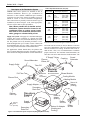
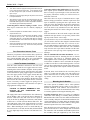
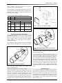
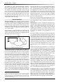
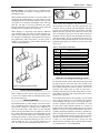
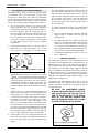
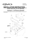
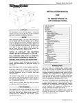
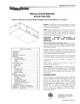
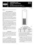
Bulletin 30-05 / May 2007
Installation Manual for
Air Distribution Systems
NOTICE TO INSTALLER AND EQUIPMENT OWNER: RETAIN THIS MANUAL AT THE JOB
General
The following information is to help the installer save time,
provide the best possible installation, and ensure continuous trouble-free operation. All Unico System components
are factory fabricated up to the point where they can be
assembled on the job as described in this manual.
Scope
These installation instructions cover the Unico System air
distribution system including the return air components
and secondary drain pans as shown in Figure 1. This manual describes only the installation of the duct components.
Details for wiring, piping, refrigerant line connections and
condensate drains are covered in the installation instructions for the specific models and accessories.
Specific design procedures are detailed in Bulletin 40-30:
Component Layout and Bulletin 40-40: System Sizing and
Layout Procedure. Although this manual will occasionally
repeat important information, refer to the design bulletins
for more detailed information on duct sizing and location.
Association (NFPA), International Residential Code (IRC),
International Mechanical Code (IMC), and Underwriters
Laboratories (UL) applicable standards and regulations. In
case of conflict, local codes take precedence.
All electrical wiring should be in accordance with the latest
edition of the National Electrical Code (NEC) and all local
codes and regulations.
Condensate piping should be installed in accordance with
governing codes. Always install a secondary drain pan
when an overflow of condensate could cause damage.
Tools Required
The following list covers the basic tools required to properly install the Unico System duct components. The list
does not include commonly available items such as sheet
metal screws, hammers, screwdrivers, etc.
1. Reciprocating saw (e.g. Sawzall®* brand or equal) with
blades to cut joist, studs and drywall.
2. 4-inch (102 mm) carbide tip rotary hole saw for plaster/lathe.
3. 3-1/2-inch (90 mm) hole saw or wood chipper type blade for
hardwood floors.
General Precautions and Safety Tips
4. Half of a basketball to fit on hole saw to catch debris.
Do not attempt to install or start up the system without first
reading and understanding this manual and the appropriate
manual for the air-handling unit.
5. UPC-57 Clamp pliers for duct clamps
6. Amp meter with low scale (less than 10 amps)
®**
7. Turbometer
Before operation, be sure the unit is properly grounded.
The installation should be in accordance with all local
codes and regulations and with the National Fire Protection
TABLE OF CONTENTS
SCOPE ...................................................................... 1
SAFETY TIPS ............................................................ 1
TOOLS REQUIRED .................................................. 1
DESCRIPTION OF SYSTEM..................................... 2
INSTALLATION ......................................................... 3
Preparation of Work Area.................................... 4
Return Air Opening.............................................. 4
Supply Ducts ....................................................... 4
Outlet Terminator ................................................ 6
Mounting the Air Handler .................................... 6
Supply Plenum Connection ................................ 7
Plenum Design ................................................... 7
Plenum Installation ............................................. 8
Plenum Takeoffs ................................................ 9
Balancing Orifices .............................................. 9
LEAKAGE REDUCTION ........................................... 9
DUCT IN UNCONDITIONED SPACE...................... 10
WINTER SHUT-OFF................................................. 10
8. UL-181A-P pressure sensitive foil tape or UL-181B-FX flexible duct tape.
Additional materials for fiberglass plenum:
1. UPC-55 2-inch (51 mm) hole cutter (“cookie cutter”)
2. UL-181A-H heat sealed aluminum foil tape or UL-181A-P
pressure sensitive foil tape
3. Iron for heat sealable tape
Additional materials for metal plenum:
1. 1-7/8-inch (48 mm) metal hole saw, or 2-inch (51 mm) as alternative.
2. Tin snips
3. UL-181A-M duct mastic or UL-181A-P pressure sensitive foil
tape.
*
**
© Copyright 2007 Unico, Inc.
air velocity meter.
Sawzall is a registered trademark of the Milwaukee Electric Tool Corp.
Turbometer is a registered trademark of Davis Instruments
Bulletin 30-05 — Page 2
Table 1. Equivalent Duct Size, inch (mm)
Description of Air Distribution System
General. Most Unico Systems are installed in attic or
overhead installations. However, give consideration to
basement or other suitable conditioned space locations,
especially since the Unico System air handlers can be installed in vertical as well as horizontal configurations.
These instructions are primarily oriented to the attic type of
installation (as shown in Figure 1) but, where appropriate,
reference will be made to other possibilities.
Round Size
Note: Where possible the air handler and air
distribution system should be located in the
conditioned space to reduce energy losses
that result in non-conditioned areas, such as
attics, garages or unheated utility rooms.
Supply Air System. All supply air is distributed through a
compact duct system consisting of a plenum and small
branch ducts. In some cases, the branch ducts may be omitted. The plenum can be any material provided it is insulated and designed for up to 3 inches of water column (744
Pa) and 2800 ft/min (14.2 m/s). Table 1 lists some common
sizes along with the maximum recommended airflow.
For applications without branch ducts, the plenum must
have acoustical dampening properties. Examples of this are
ducts made from fiberglass insulation such as ductboard or
Supply Outlet
7.0
(178)
6-1/2 x 6-1/2
6x8
4 x 12
3-1/2 x 14
(165 x 165)
(152 x 203)
(102 x 305)
(89 x 356)
600 CFM
(330 L/s)
9.0
(229)
8-1/2 x 8-1/2
8 x 10
6 x 12
4 x 20
3-1/2 x 24
(216 x 216)
(203 x 254)
(152 x 305)
(102 x 508)
(89 x 610)
1000 CFM
(472 L/s)
10.0
(254)
9-1/2 x 9-1/2
8 x 12
6 x 14
4 x 24
(240 x 240)
(228 x 305)
(152 x 356)
(102 x 610)
1250 CFM
(590 L/s)
11.0
(279)
10-1/2 x 10-1/2
10 x 12
8 x 14
6 x 18
(267 x 267)
(254 x 305)
(203 x 356)
(152 x 457)
1500 CFM
(708 L/s)
metal ducts with internal fiberglass insulation lining.
All branch runs are 2-inch (51 mm) in diameter. Unico has
two types of branch ducts: UPC-26C Sound Attenuator and
UPC-25 aluminum core tubing. All branch ducts must include at least 3 feet (1 m) of sound attenuator to maintain
proper sound levels. For maximum sound attenuation, the
entire duct run can be made from the sound attenuator. The
2" Supply Tubing
Plenum
Elbow, 90°
Sound Attenuator
Maximum
Airflow
Rectangular Equivalent
Coupling
Sound
Attenuator
Take-Off
Modular
Fancoils
Full Flow Tee
Restrictor
(incl.
w/ blower)
Plenum Duct
Blower Module
M2430/3642/4860
Cooling Module
Heating Module
Return Air
Adapter
(Cooling)
Supply Adapter
Secondary
Drain Pan
M1218
Supply
Adapter
Turning
Vane
(for Tee)
Secondary
Drain Pan
Figure 1. Air Distribution System components (fiberglass plenum shown)
© Copyright 2007 Unico, Inc.
Return Air
Adapter
(Heating)
Return
Air Duct
Return Air Adapter
(Heating and
Cooling)
Return
Air Box
IL00343a.CNV
One-piece
Fancoil
Plenum
End Cap
Bulletin 30-05 — Page 3
ducts are available with four different insulation thicknesses to achieve higher R-factor ratings: R3.2 (STD), R4.2, R-6, and R-8.
The entire branch duct can be made of the sound attenuator
(method A, Figure 2) or with 3 feet (1 m) of sound attenuator and the rest made of aluminum supply tubing (method
B, Figure 2). For branch runs over 12-feet (3.6 m) long,
method B recommend because the aluminum duct is
stronger than the sound attenuator and long runs usually
are handled more roughly.
Note: For proper acoustical attenuation, always
use at least 3 ft (1 m) of sound attenuator supply
tubing at the end of each run.
Supply Outlet
(UPC-56B,
UPC-57, or
UPC-58-1-XX)
Sound Attenuator Supply Tubing (12 ft. Max.)
(UPC-26C)
Scrim Core Clamp
(UPC-53)
Method A (for 6 to 12 ft.
Scrim Core Clamp
(UPC-53)
Takeoff
(UPC-23B
runs)
or UPC-28)
Alum. Core
Clamp
(UPC-52)
Aluminum Core Supply Tubing
(UPC-25)
Scrim Core Clamp
(UPC-53)
Takeoff
Supply Tubing Coupling
(UPC-38C)
IL00111a.CVS
Method B (for 6 to 50 ft. runs)
Figure 2. Branch duct assembly
The branch ducts terminate with either a round or rectangular outlet. The outlets come in a variety of colors and
finishes, including several species of wood, unfinished.
The round outlets are usually the best choice for floor or
ceiling outlets. The rectangular outlets are ideal for outlets
in a wall and are designed for standard 2 x 4 construction.
The rectangular or ‘slot’ outlets are available in both cast
aluminum and plastic. In addition Unico has an angled
round outlet designed for sloped ceilings. For applications
without branch ducts use the plenum slot outlets, part
number UPC-101.
For certain applications where it is desired to attach the
outlet as close as possible to the plenum, a 12-inch (31 cm)
rigid sound attenuator is available. These attenuators are
available in kits. Use kit UPC-84-5 for fiberglass plenum
and kit UPC-85-5 for sheet metal plenum. The kits include
all the necessary components to complete an outlet branch
run. These kits are well suited for masonry or concrete
structures with no ceiling joists or crawl spaces. They can
also be used for under-slab installations. See Bulletin 2060: Rigid Sound Attenuator for installation details.
For exposed duct applications, use the UPC-101 slot outlet
attached directly to the plenum. This is acceptable as long
as 7 outlets per nominal ton (2 outlets per nominal kW) are
© Copyright 2007 Unico, Inc.
Return Air System. Unico supplies factory made components for the complete return air system that includes the
return air box with grille and filter, return air duct and return air adapter. These components are ideal for horizontal
attic type installations where one central ceiling return can
be used.
Where the single packaged return air system can not be
used, such as in tight closets, vertical installations or where
multiple returns are needed, a field fabricated return duct
system made from ductboard, or sheet metal with acoustical lining can be used. A 90° bend or elbow should be used
in the field fabricated return system for proper acoustical
performance.
Each Unico System air handler is designed with a rectangular return air opening that will accommodate the field
fabricated duct which should be designed for a pressure
loss not to exceed .15 inches of water column (IWC) (37
Pa), including filter. Generally, this means sizing the duct
for a pressure loss of .05 IWC at the required airflow and
sizing the filter for a pressure drop of .10 IWC at the required airflow. It may help to remember that the return
duct system is a conventional design, not high velocity. For
most systems, the minimum duct size is sufficient for up to
25 feet (8 m) with no more than three 90° bends (Table 2).
Supply Outlet
3 ft. min Sound Attenuator Supply Tubing
used and the plenum is acoustically lined or made of fiberglass ductboard.
Note: For more detailed information on return duct design
see Tech Note 106, Return Duct System Design Requirements.
Table 2. Minimum Return Duct Size
Model
Part No.
Diameter
1218
UPC-04-1218
12 in. (305 mm)
2430
UPC-04-2430
14 in. (356 mm)
3642
UPC-04-3642
18 in. (457 mm)
4860
UPC-04-4860
20 in. (508 mm)
4860
UPC-04-4860NC
20 in. (508 mm)
Length
10 ft. (3 m)
General Installation Procedure
The following procedure is a general guideline describing
the most popular installation sequence. It is not required to
proceed in the same order; however, each step must still be
done.
1.
Produce sketch of duct design showing approximate location of all outlets, the air handler, the return openings,
and a layout of the supply plenum and return duct.
2.
Locate and cut the openings for the outlets and the return air openings.
3.
Install the branch ducts.
4.
Install the outlets and mount to floor or ceiling.
5.
Mount the air handler
6.
Install plenum
7.
Connect branch ducts to plenum
8.
Install return grille and return duct
Bulletin 30-05 — Page 4
9.
Connect electrical power
vided in the long sides of the return air box. Use the four
(4) ¼-inch (6.4 mm) holes nearest to the corners. The other
holes are for mounting the filter grille (Figure 3).
10. Test airflow
11. Connect refrigerant lines and charge
Install filter frame into the return air box using four (4)
nails or screws. Use the holes furthest from the corners.
Insert filter and hold in place by rotating metal clips. Close
grille and secure with clips.
12. Fill out service report form for records
Preparation of Work Area
It is recommended that good lighting and a fan be provided
when working in poorly ventilated attic or crawl areas. The
fan can be set over the return air opening and used to force
cooler air into the area during installation. Another useful
tip is to run a sprinkler on the roof during installation to
keep the attic temperature down.
For attic and crawl space installations many installers find
it practical and easier to use “working boards” laid over the
open joists or on the ground. These are 16-inch (41 cm)
wide plywood sheets 8-foot (2.4 m) long. They are saved
and carried from job to job.
Return Air Opening
Cut the opening for the return air box in accordance with
the dimensions of Table 3. By doing this first it provides an
opening to move equipment and components into the attic
when other access is not sufficient.
Models
Return Air Box Part No.
Size of opening
inches (mm)
1218
UPC-01-1218
14 3 8 x 20½ (365 x 520)
2430
UPC 01-2430
14 3 8 × 25 ½ (365 × 648)
3642
UPC 01-3642
14 3 8 × 30 12 (365 × 775)
UPC-01-4860
24 3 8 × 30 12 (619 × 775)
UPC-01-4860NC
20 3 8 × 30 12 (517 × 775)
If the joists or studs are less than 16 inches (41 cm) centerto-center or in the wrong direction, it will be necessary to
cut and header the joists or build a frame to hold the return
air box. Center the return air box so the filter frame flange
covers all the gaps and make sure the flange is flush
against the wall or ceiling. Install the return box inside the
surrounding frame using nails or screws. Holes are pro-
FRAMING
RETURN AIR BOX
FILTER FRAME
FILTER
FILTER GRILLE
IL00048.CNV
Figure 3. Return Air Box and Filter Grille
© Copyright 2007 Unico, Inc.
Supply Outlet and Branch Run Installation
Parts Required. Each branch run is made entirely of
sound attenuator duct or sometimes connected to an aluminum duct. All the items necessary for branch construction,
including plenum connections and terminations, are listed
in Table 4.
Table 4. Branch Run Parts
Part No.
UPC-26Cxx-6
UPC-25xx-4
Table 3. Return Air Box Opening
4860
Connect the return air adapter to the unit using sheet metal
screws. Then attach the return duct to the adapter and to
the return air box using the Q-bands and Q-clips. The return air adapter ships with an insulation blanket that must
be wrapped around the adapter. Tape the seams with UL
181A-P aluminum tape.
UPC-89F-6
UPC-89M-6
UPC-80F-1
UPC-80M-1
Description
Sound Attenuator Tubing, (6) 12 ft (3.6 m) lengths
(xx - indicates optional R-factors, R4/R6/R8)
Aluminum core Supply Tubing, (4) 25 ft (7.3 m)
lengths (xx – indicates optional R-factor, R4/R6/R8)
Installation Kit (for fiberglass plenum), 6 outlets,
includes takeoffs, clamps and couplings
Installation Kit (for metal plenum), 6 outlets, includes takeoffs, clamps and couplings
Outlet Kit (for fiberglass plenum), single outlet with
12 ft (3.6 m) sound attenuator
Outlet Kit (for metal plenum), single outlet with 12 ft
(3.6 m) sound attenuator
UL181A-P Aluminum Tape
All the necessary items to make a 12-foot (3.6 m) branch
run from the plenum to the supply outlet are available in
the single outlet kits. For lengths grater than 12-foot (3.6
m), the 2-inch (51 mm) aluminum supply tubing must be
ordered separately. The materials are also available in bulk
packaging with the outlets and hardware sold as a 6 outlet
Installation Kit and the sound attenuator sold separately.
Outlet types. There are several types of supply outlets,
each of which was designed for a specific application although all of them can be used for various applications.
The standard outlets are white plastic which can be painted
to match the wall and are also available with a metallic
finish. Outlets are also available with a wood faceplate
made of unfinished oak as standard or other wood species
as a special. Consult Unico for availability of colors, finishes, and wood species.
The basic round outlets are designed for ceiling and floor
applications although it is not unusual to place them in the
side wall. The sloped outlets are a variation of the round
outlets and are designed for sloped ceiling applications.
The round outlets with wood faceplates are designed primarily for floor applications and come standard with a
screen. The slotted outlets are designed for side wall appli-
Bulletin 30-05 — Page 5
cations or low clearance dropped ceilings. Their advantage
is that they are available with a 90° elbow to facilitate installation in tight spaces.
1.5 meter over 3 meters). For example, a 30 foot (9 meter)
run is 60% of an outlet that is 10 foot (3 meters) yielding a
reduction of 40% (30-10=20, 20÷5=4, 4×10=40%).
Installation of Supply Runs. Supply outlet locations
should be pre-determined in accordance with the prepared
layout following Bulletin 40-30: Component Layout.
After the approximate location of the outlet is determined a
hole must be cut and the supply tubing routed to the outlet
location. Follow these steps when installing the supply
tubing:
The outlets can be placed in the ceiling, floor or wall. The
best place for ceiling outlets is the corner – center of hole 5
inches (125 mm) from each wall, or 3 inches (75 mm) from
each wall if using the slotted outlet (Figure 4). If that is not
possible or practical, anywhere out of the traffic pattern is
acceptable.
3
(75)
Make branch runs at least 6 feet (1.8 m) to prevent noise from
excessive air flow. The entire branch duct can be sound attenuator or it can be a combination of sound attenuator coupled to the aluminum supply tubing. In either case, each
branch duct must have at least 3 feet (1 m) of sound attenuator at the end.
2.
Use as few bends as possible.
3.
If bends are necessary, provide as generous a bend radius as
possible. The minimum radius is 6-inches (152 mm).
4.
Support the supply tubing every 4 feet (1.2 m).
5.
Be careful not to tear or puncture the supply tubing outer
jacket.
5
(125)
3
(75)
1.0 x 9.25
(25 x 235)
5
(125)
IL00348.CNV
4
(100)
1.
Figure 4. Location of corner outlets
For round floor outlets, be sure an outlet screen (UPC-88)
is installed to prevent objects from falling into the duct.
This screen is included with the UPC-57 unfinished wood
outlet.
WARNING: ADVISE THE HOMEOWNER THAT
THE SCREEN IS NOT DESIGNED TO HOLD
WEIGHT. TO PREVENT POSSIBLE INJURY DO
NOT STEP ON SCREEN.
For side wall outlets, position the outlet above head height
as near to the ceiling as possible. The standard round supply outlet can not be installed in a stud wall as there is insufficient room to bend the sound attenuating tubing. For
such installations use the slotted outlet. Otherwise, if there
is room for a bend radius 6 inches (152 mm) or greater,
such as a soffit above a kitchen cabinet or space above
closet doors, it is acceptable to use a round terminator.
For refrigerant cooling applications, the airflow must be
between 200 and 250 CFM per nominal ton (27 to 33 L/s
per nominal cooling kW). For hot water or chilled water
systems, refer to performance charts to determine the required airflow. The allowable airflow range per outlet is
20 to 40 CFM (9.4 to 19 L/s), where the typical outlet will
deliver 35 CFM (17 L/s) if the plenum static pressure is 1.5
inches (0.37 kPa) and the branch duct length is 10-foot (3
meters) without any balancing orifices. Therefore, the
average project will require about 6 outlets per nominal ton
(6 outlets per 3.5 kW) although more will be needed if the
branch ducts are longer, balancing orifices are used, the
plenum static pressure is less than 1.5 inches of water (0.37
kW), or it is desirable to make the system as quiet as possible. For example, two runs with 50% balancing orifices
are equal to one branch run without any orifices.
For supply ducts longer than 10 feet (3 meters), the air is
reduced in that run by 10% for every 5 feet over 10 (every
© Copyright 2007 Unico, Inc.
For New construction Applications (round outlets):
1.
Install a plaster frame kit (UPC-86) where the outlet will be
located. See Bulletin 20-80, Plaster Frame Kit.
2.
Route the supply tubing so about 6 inches (152 mm) of the
attenuator protrudes through the hole in the plaster frame.
3.
If you have access to the plenum after terminator is secured,
do this step last. Be sure there is sufficient tubing to provide
as generous a radius (6-inch minimum) as possible at the outlet. Remove the excess supply tubing at the plenum and connect to the plenum takeoff.
4.
Push the duct up into the hole and install the drywall or paneling, cutting the appropriate 4-1/4-inch (108 mm) hole for the
frame.
5.
Pull the duct out and attach the duct core to the outlet terminator. Be sure to cut off any excess core. DO NOT ALLOW
THE CORE OF THE DUCT TO ‘BUNCH UP’ AND DO NOT
CREATE A SHARP BEND NEAR THE OUTLET – THIS CAN
CREATE NOISE.
6.
Position the terminator in the hole and secure with toggles
and screws.
For New construction Applications (slotted outlets):
1.
Install the outlet inside the wall cavity using the mounting
bracket and hanger bars. See Bulletin 20-70, Slotted Outlet
Specifications.
2.
Route the sound attenuator from the outlet to the plenum.
3.
Connect the sound attenuator to outlet and takeoff with the
clamps and then seal the vapor barrier with aluminum foil
tape.
4.
Install the gypsum board and finish the interior wall. Then
attach the trim plate.
For Existing Structures (round outlets):
1.
Cut a 4-inch (102 mm) hole in the plaster or drywall. To be
sure there is adequate clearance around the outlet location so
the 4-inch (102 mm) hole can be cut without running into any
obstructions, first drill a small (1/8-inch (3 mm)) hole at the
outlet location and check above the ceiling or below the floor
to see that there is 2-inch (51 mm) clearance all around the
hole. After assuring adequate clearance, cut the 4-inch (102
mm) hole with a rotary hole saw using the small hole as a pilot
hole.
Bulletin 30-05 — Page 6
2.
Then either route the supply duct through the hole to the plenum or from the plenum to the hole. If it is necessary to pull
the duct through a floor joist, use either an electrician’s “fish
tape” or rope.
3.
Remove any excess supply tubing at the plenum and connect
to the plenum takeoff.
4.
Allow about 6 inches (152 mm) to protrude through the hole,
removing any excess and connect to the outlet terminator.
Remember that as generous a radius as possible is desired at
the outlet for good acoustical performance.
Connecting Duct to takeoff, coupling or outlet. Follow
these steps to connect the duct to a takeoff, coupling or
outlet:
1.
Pull back the jacket and insulation about 2 inches (51 mm) to
expose the inner core.
2.
Slip the core over the connection stub of the takeoff, coupling
or outlet as far as you can. Then secure with clamp using
clamp pliers (UPC-54). Use the UPC-53B clamp for clamping
the sound attenuator core and the UPC-52 clamp for clamping
the aluminum core.
3.
Stretch the insulation and outer jacket over the core and stub
and stuff under the tape ring. Secure the outer jacket with
UL181A-P aluminum tape.
Duct Penetration between Floors
Whenever you penetrate a floor with the ducts, special care
must be taken to assure that the installation is in compliance with the building codes. There are several different
methods of installation, depending on the application.
Outlet Terminator Installation
With the outlet terminator connected to the end of the
sound attenuator install the two toggles and screws in the
mounting holes in the terminator faceplate. Feed or pull the
terminator through the 4-inch (102 mm) hole in the ceiling
or floor until the two spring toggles begin to enter the hole.
Force the upper portion of the toggles inward until they
snap over the edge of the ceiling or floor. The toggles
should be centered on a line parallel to the direction of the
duct run from the outlet to the plenum takeoff. Loosen the
screws if necessary to assure toggles are sprung over the
edge of the hole. Tighten the screws until the cover plate is
snug against the ceiling or floor.
CAUTION: TO PREVENT DAMMAGE TO THE
OUTLETS DO NOT OVERTIGHTEN THE
TOGGLE SCREWS.
The supply outlet can be installed in the floor without toggles by drilling a hole 3-3/8-inch (86 mm) in diameter instead of 4-inch (102 mm) and screw the cover plate directly to the floor by drilling two 5/64-inch (2 mm) diameter holes on a 3-3/4-inch (95 mm) diameter bolt circle. The
UPC-56B supply outlet can be inserted into the 3-3/8-inch
(86 mm) hole and used as a template for the two screw
holes. When installing the screws be careful that they do
not break into the 3-3/8-inch (86 mm) hole; drill and install
at a very slight angle away from the 3-3/8-inch hole if necessary.
© Copyright 2007 Unico, Inc.
Connecting Outlet to R-6 and R-8 duct. The R-6 and R-8
ducts require special installation instructions because the
duct is too large to pass through a 4-inch (102 mm) hole.
To properly install these outlets you will need access to
both sides of the wall.
These ducts have two layers of insulation and two vapor
barriers. Simply peel back the outermost vapor barrier and
layer of insulation, exposing the inner vapor barrier. The
inner layer is the same thickness as the R-4.2 and will pass
through the 4-inch hole. Then clamp the inner duct and
seal it the same as any standard or R-4.2 duct. Push the
outlet into place and secure it to the ceiling or wall with the
toggles.
From the backside of the wall unroll or unpeel the outer
insulation and vapor barrier to its previous position. Then
tape any seams with UL-181A-P tape.
If you do not have easy access to backside of the wall, then
you will need to attach a short length of standard sound
attenuator to the R-6 or R-8 duct. Use a 3-foot (1 m) section of sound attenuator coupled to the inside vapor barrier
of the heavier insulated duct. Push the outer insulation
away from the outer vapor barrier and then seal the outer
vapor barrier to the tape ring of the coupling with aluminum tape.
UPC-57 Unfinished Wood Outlet Installation. Cut a 33/8-inch (86 mm) hole for mounting the UPC-57 without
using toggles. The UPC-57 is furnished without any
mounting holes in the wood faceplate. Rather than mar the
wood surface an adhesive can be used under the faceplate
to adhere it to the floor or other mounting surface. In some
cases for floor applications the weight of the tubing below
the floor will keep the outlet in place without any retention
means.
If desired, holes can be drilled in the wood face plate at
about a 3-7/8-inch (98 mm) bolt circle and wood screws
used to mount the UPC-57 directly to any wooden mounting surface, such as the floor or paneling on the wall or
ceiling.
Mounting the Air Handler
The Unico System air handlers can be either platform
mounted or suspended from the ceiling or attic rafters as
detailed in Bulletin 30-20: Modular Unit Installation Instructions. The M1218 can be mounted flush to the ceiling
or vertically against a wall using the mounting rails.
Secondary Drain Pan. Where an overflow of condensate
could cause water damage, a secondary drain pan MUST
BE INSTALLED. Table 5 lists the models and dimensions
of the secondary drain pans for horizontal installations. For
vertical installations a secondary drain pan should be fabricated so the dimensions are about 2 inches (51 mm) greater
than the footprint of the base of the air handler.
Place the drain pan on the mounting base, platform or angle iron frame. Be sure to allow enough room for the drain
line connection. The assembled unit should be placed over
the secondary drain pan supported by rails with rubber
Bulletin 30-05 — Page 7
pads for isolation to raise the unit above the 1.5-inch (38
mm) sides of the secondary drain pan.
Like the modules, all secondary drain pans except UPC24C and 24D will fit through the return air opening. Those
drain pans may simply be folded and unfolded to fit
through the return opening.
Table 5. Secondary Drain Pan Dimensions, inches (mm)
Model
Part No.
Size
1218
UPC-94
40 x 22 (1016 x 559)
2 Modules
Model
3 Modules
Part No.
Size
Part No.
Size
2430
UPC 20B
27 × 29.5†
(686 × 749)
UPC 20C
27 × 41.75†
(686 × 1060)
3642
UPC 24B
40 × 29.5†
UPC 24C
(1016 × 749)
40 × 41.75†
(1016 × 1060)
4860
UPC-24C
40 × 41.75†
UPC-24D
(1016 × 1060)
40 x 54†
(1016 x 1372)
† NOTE — The drain fitting extends 7/8 inch (22 mm) beyond this dimension.
Figure 7. Square plenum adapter installation.
Blower
Module
Restrictor
Plate
Plenum Connection to Air Handler
Install Plenum Adapter. Use the UPC-61 supply plenum
adapter for round metal plenum (Figures 5 and 6). Use the
UPC-62 supply adapter for square fiberglass ductboard
plenum (Figure 7). Any other shapes or sizes require a
field installed adapter.
Plenum Adapter
First install the restrictor plate on the blower (Models
M2430, M3642, and M4860 only). Position the restrictor
Plenum
Insulation Wrap
IL00308.CVX
Figure 5. M2430/M3642/M4860 Round Plenum Adapter Installation
Blower
Cabinet
tape. Make the blanket snug but not compressed to maximize the insulation effect.
Plenum Adapter
Plenum
Insulation Wrap
IL00155.CV5
Figure 6. M1218 Plenum Adapter Installation
in the ‘full open’ position with the screws tight but still
able to move the restrictor.
Connecting Metal Plenum to Plenum Adapter. To connect a metal plenum, slip the un-crimped end of the plenum duct over the crimped end of the adapter. Secure the
duct with a minimum of three self-tapping sheet metal
screws at the joint and seal all seams with UL-181A-P
pressure sensitive tape or UL-181A-M duct mastic. Then
wrap the 1-inch (25 mm) thick fiberglass blanket insulation
around the UPC-61 adapter and seal again with UL181A-P
© Copyright 2007 Unico, Inc.
Connecting Fiberglass Plenum to Plenum Adapter. Cut
off the male ship-lap to make the end flush; then insert the
duct into the plenum adapter. Push plenum in tightly to
form a snug joint. Insert four large headed nails at least 1inch (25 mm) long through the four holes on each side of
the square plenum adapter to help secure the duct. Then
seal the duct to the metal collar with UL-181A-P tape. Be
sure to use a squeegee to adhere the tape. After the duct is
sealed to the adapter, wrap the supplied insulation tape
around the exposed metal of the adapter to prevent condensation.
Plenum Design
As described in Bulletin 40-30, the best plenum design is
the perimeter loop because it uses a tee to split the flow.
This effectively reduces the pressure drop of the entire duct
system and also boosts the plenum static pressure. For best
performance, the tee should be the first fitting coming off
the air handler at least 4 feet (1.2 m) away, but no closer
than 24 inches (61 cm).
Bulletin 30-05 — Page 8
The plenum size, using internal dimensions, should be
based on the maximum airflow shown in Table 1. For simplicity and to take maximum advantage of static regain, do
not downsize the plenum except where needed for tight
spaces. In some cases, when the plenum equivalent length
is over 150 feet (45 m), the plenum should be oversized.
For example, the M2430 with 550 CFM (259 L/s) will use
a 7-inch (18 cm) ID plenum per Table 1. However, if the
equivalent plenum length is over 150 feet (45 m), it should
be upsized to 9-inch (23 cm) ID.
Plenum Installation
Fiberglass Plenum. Before beginning plenum installation
it will save on fabrication of plenum joints if the layout is
consulted as to the location of tees and elbows in relation
to the air handler. Proper planning at the outset as to the
match-up of these joints can save on having to fabricate
ship-lap joints when the standard 4-foot plenum lengths are
cut to shorter lengths.
Where fiberglass is used, the plenum, tees, and elbows are
supplied with pre-fabricated male and female ship-lap*
joints on each end. Tees and elbows are supplied with male
and female ends as shown in Figure 8.
Female
Male
Figure 8. Tee and Elbow End Configurations
Once the duct sections are fitted together, use either UL181A-H heat seal tape (UL-181A-P pressure sensitive tape
or UL-181A-M duct mastic may also be used) to connect
the sections together. The UL-181A-H is a heat seal tape
that requires the use of a hot iron. Done properly, it is the
most secure joining method. However, it is difficult sometimes to maneuver the iron when you are in tight spaces.
Therefore, as alternative, use the UL-181A-P tape or UL181A-M duct mastic to join the sections. Be sure to use a
small squeegee to apply pressure to the tape. And always
be sure that external surface of the duct is clean. For more
information, refer to the manufacturer of tape, regarding
shelf life, surface preparation and application temperatures
for these closure systems. Continue to assemble plenum
making sure ship-lap joints are snug. Tape each joint securely with UL181A-H heat activated tape (available as
UPC-17). For square plenum use a short 4-inch (102 mm)
piece of tape on each side of the ship-lap joint taping
*
The pre-fabricated male and female ends on the plenum and plenum
fittings are most commonly called ship-lap joints. Tools are available to
facilitate fabrication of the male and female ship-lap joints on the ends of
the plenum. Alternatively, a utility knife can be used to form ends. Ends
properly cut should fit snugly.
© Copyright 2007 Unico, Inc.
across the flap. Be sure to pull flap tight before ironing.
Once all four sides are secured, tape completely around the
duct. As each length of plenum is added be sure it is properly supported so no strain is put on the joints. The square
tees and elbows have tape flaps on all four sides of each
male ship-lap joint. The end cap has extra foil facing that
extends on each side to serve as a tape flap. To facilitate
folding the flap over each side of the plenum the end cap
flap can be cut at each corner.
Be sure tape is centered over the joint and provide an overlap of at least 2 inches (51 mm) at the end of the tape before ironing. Be sure surface of plenum is clean and free of
dust or dirt.
Metal Plenum. All joints, including the longitudinal snaplock seam in the metal pipe and the tee and elbow joints
must be sealed with UL181A-P tape to prevent any air
leakage. The complete metal plenum system should be
insulated with a minimum of 1.5 inches (38 mm) of fiberglass insulation with vapor barrier. Where higher R factors
are desired, the thickness of the insulation can be increased.
Insert male crimped ends into the un-crimped female end.
Use a minimum of three self-tapping sheet metal screws to
mechanically secure each plenum joint, including the one
at the plenum adapter. Tape each joint using UL-181A-P
pressure sensitive tape or use UL-181A-M duct mastic. Be
sure that all longitudinal seams of the metal pipe are also
sealed with tape. It is also helpful to locate the longitudinal
seam at one location such as at the top of the pipe as once
the pipe is insulated the longitudinal seam is to be avoided
for cutting holes for the attachment of the plenum takeoffs.
Insulate the bare metal with a minimum of 1-1/2 inches (38
mm) of fiberglass insulation with vapor barrier and tape
securely in place. Use either an aluminum foil faced fiberglass insulation blanket or a silver insulation sleeve. Tape
all insulation seams with UL-181A-P or UL-181B-FX
tape. Be careful not to compress the insulation while wrapping it around the duct or while taping the seams.
When using metal plenum, be sure that the elbows have a
generous radius and the tees are the full flow design. All
joints in tees and elbows must be sealed with UL181A-P
tape before insulating. Never use an elbow as the first fitting off the air handler; always use a least 24 inches (61
cm) of straight duct before the elbow and use large radius
elbow. If a tee is not used, maintain the maximum duct size
whenever possible. Reduce the duct size only if the plenum
equivalent length is less than 150 feet (46 m) and the airflow is below the maximum allowable in Table 1.
Accidental punctures or tears in the plenum facing should
be repaired to minimize leakage and provide a neat appearance. If the damaged area is small repair it with the same
tape as used for sealing the plenum joints or vapor barrier.
Where large areas of the facing have been damaged in fiberglass duct remove the section of damaged duct and replace with new duct, using ship-lap joints at both ends.
Bulletin 30-05 — Page 9
Plenum Support. The plenum can be extended horizontally and rest directly on floor or ceiling joists or be suspended from above.
When hanging or supporting metal plenum, additional
steps should be taken over those used with fiberglass plenum to avoid condensation at the points of support since
the fiberglass surrounding the metal plenum will compress
and significantly reduce the R-factor. At these points a
saddle of rigid fiberglass or foam rubber should be provided to rest the plenum in.
IL00096
When hanging fiberglass plenum, be sure the hanger will
not damage the plenum facing. Use either plastic or metal
strapping material with minimum width of 1-inch (25 mm)
(see Figure 9). Covering the metal hanger with a cloth type
duct tape will help to avoid the puncturing the facing.
Hangers should be no greater than 6 feet (1.83 m) apart and
located as close to plenum joints as practical.
15°
IL00091.CVS
Figure 9. Plenum Takeoff Location
These orifices are mounted at the UPC-23 or UPC-28
takeoff fittings. The orifice cap alone provides the 15%
reduction, the cap with the .266-inch diameter hole disc
provides 35% reduction and the cap with the .188-inch
diameter hole disc provides 50% reduction in airflow. The
discs are designed to just press into the orifice cap before
installing over the connector stub protruding from the plenum takeoff fitting. The cap is designed to fit snugly over
the connector stub and still permit the 2-inch (51 mm) ID
insulated supply tubing core (UPC-25 or UPC-26) to slide
freely over it.
Table 6. Outlet-Orifice Combination
1" (min.)
24 gauge
1" (min.)
24 gauge
il00199.CNV
1" (min.)
24 gauge
Figure 10. Hanging Fiberglass Plenum
Plenum Takeoff Installation
Refer to Bulletin 30-50: Plenum Take-off Installation Instructions for complete details for attaching the take-offs to
the plenum (Figure 10).
Balancing Orifices
The Installation Kits (5 outlet) include one of each of the 3
sizes of balancing orifices. The UPC-35-15 Takeoff Balancing Orifice Package is available where additional orifices are needed. They reduce airflow for the individual
branch runs to better balance the air supplied to rooms for
the cooling and heating loads. Upon completing the individual room heat gain and heat loss calculations and determining the number of outlets, the runs requiring orifices
should have been determined allowing for the 3 sizes of
orifices which give 15%, 35%, and 50% reduction in air
flow. See Table 6 for the combinations that can be used.
© Copyright 2007 Unico, Inc.
Desired
Number of
Outlets*
.5
(1) .5
.65
(1) .35
Outlet-Orifice Combination
.85
(1) .15
1.00
(1)
1.15
(1) .5 + (1) .35
1.30
(2) .35
1.50
(1) .35 + (1) .15 or (1) + (1) .5 or (3) .5
1.65
(1) + (1) .35 or (2) .5 + (1) .35
1.70
(2) .15
1.80
(2) .35 + (1) .5
1.85
(1) + (1) .15
1.95
(3) .35
2.00
(2)
* For a room requiring more than 2 outlets use combinations of above table quantities.
Reduction of Leakage and Energy Losses
For fiberglass plenum systems with all plenum joints taped
carefully using the UL181A-H tape, there should not be
any leakage from joints or be any need to mechanically
brace plenum fittings into which air impacts. This may be
necessary when other tapes are used. In such cases, a
caulking compound (such as DAP butyl rubber) or fiberglass adhesive should be used at all plenum joints to reduce
leakage and energy losses.
In unconditioned locations, and especially in more humid
areas, it may be necessary to over-wrap the joints with foilfaced fiberglass and tape in place covering all edges to
provide a complete vapor barrier. The R-factor of 1 inch
(25 mm) thick square fiberglass plenum is 4.2. Where a
higher R factor is desired it is usually better to use a metal
plenum as it can be over-insulated with thicker insul-sleeve
or blanket insulation with thicker insulation. Alternatively,
thicker fiberglass ductboard may be used but this complicates the installation because the elbows and tees must be
fabricated in the field. Several manufacturers make a 11/2-inch (38 mm) ductboard (R-6) (2-inch (50 mm)
ductboard is also available in R-8). Special spin-in takeoffs
are available for the 1-1/2-inch ductboard.
Bulletin 30-05 — Page 10
Duct System in Unconditioned Spaces
5.
In extreme humidity areas the air handler can also be
protected against condensation by covering the top,
sides and ends with foil-faced duct board. All bare
ends and joints should be taped with UL181A-H to
give a complete vapor barrier. Since side panels and
the control box cover may have to be removed, leave
cut outs or taped pieces (use UL181A-P tape) that can
be easily removed.
6.
A complete distribution system can be supplied that
provides an R-factor of 6 or higher using the following:
To minimize energy losses it is best to run the duct system
in conditioned spaces, such as basements, utility rooms,
and closed or furred down areas. When the distribution
system is located in unconditioned spaces and especially in
the more humid areas of the country, it may be necessary
to take extra precautions against condensation as follows:
1.
2.
Be sure tape rings are used at every 2-inch (51 mm)
tubing connection. They are specifically intended to
keep the insulation from being compressed whenever a
joint is being taped. Since the connection joints are
more susceptible to leakage and condensation they can
be over-wrapped with a 6-inch (152 mm) wide piece
of foam insulation tape or fiberglass insulation with a
vapor seal. All edges of the fiberglass overwrap should
be taped with UL181A-P tape to assure a complete
vapor barrier.
a.
Both the Sound Attenuator and the aluminum
supply tubing are available with an R-4.2, R-6,
and R-8 rating.
b.
Use metal plenum and over-insulate with insulation sleeve or blanket insulation. Square fiberglass
plenum can be made from either 1 inch (25 mm)
or 1-1/2-inch (38 mm) ductboard to provide R-6.
This complicates making plenum takeoffs and requires special tees, elbows and plenum adapter.
c.
For additional information refer to Tech Note 102,
Duct Condensation.
At the takeoff fitting (UPC-23 or UPC-28), cuffs of
Rubatex® type or equivalent tubing 3-1/4 x ¼-inch
(82 x 6 mm) or 3/8 x 6-inch (10 x 152 mm) long can
Winter Air Shut-off
be slipped over the supply tubing and pushed snugly
against the plenum vapor barrier (Figure 11). A good
adhesive, such as DAP® butyl caulking compound or
equivalent, can be used to seal the end of the Rubatex
cuff to the plenum vapor barrier. The other end of the
cuff should be sealed to the supply tubing jacket with
UL181A-P tape to form a complete vapor barrier. The
caulking compound can be used to fill this joint before
taping.
3.
Similar to step two (2), precautions can be taken at the
supply outlet (UPC-56B). Use a similar Rubatex cuff
and slip this piece over the scrim core tubing where it
is connected to the supply outlet. Notch or compress
the Rubatex so it slips over the taping collar of the
UPC-56B between the collar and toggles so the
Rubatex can seat against the back of the supply outlet
face plate; adhesive can be used to seal cuff to back of
face plate. To facilitate the installation this cuff might
be pre-assembled to the supply outlet-scrim core tubing connector assembly taking care that the toggles are
free to compress and snap over the ceiling or floor.
4.
Plenum joints can be over wrapped with 6-inch (152
mm) wide vapor barrier faced insulation and taped in
place covering all edges to provide a complete vapor
barrier.
© Copyright 2007 Unico, Inc.
In addition to the winter shutoff caps, be sure to seal the
return air opening. Use both plastic sheet and tape to seal
the filter in place or wrap the filter with plastic so that no
air enters the return.
BE SURE THE HOMEOWNER UNDERSTANDS THE WINTER SUPPLY SHUTOFFS
AND THE RETURN AIR SHUTOFF PLATE
ARE TO BE INSTALLED AT THE BEGINNING OF THE HEATING SEASON AND
MUST BE REMOVED WHEN THE COOLING
SYSTEM IS STARTED IN THE SPRING.
IL00351.CNV
Figure 11. Extra insulation around takeoff connection.
For cooling only systems where the air distribution system
is located in an unconditioned space, such as the attic or an
unheated garage or utility room, steps must be taken to
keep moisture from collecting in the duct and plenum system during the winter months. Winter supply air shut-off
plugs are included in the Installation Kits. They can also be
ordered separately in kits of 20 as UPC-42-20. These plastic plugs fit into the supply outlet opening. Push them in
until they seat against the ledge inside the mouth of the
supply outlet (see Figure 12).
Figure 12. Installing winter shutoff caps.