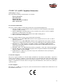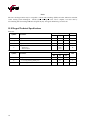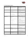
1
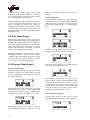
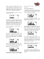
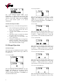
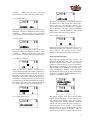
USER MANUAL Reply Plus Applies To: Keypad, Model WRS7200 (Firmware Revision 2.x) Copyright 2007 -2008 Fleetwood Group, Inc., Electronics Division. All rights reserved. Licensed software products are owned by Fleetwood Group, Inc. or its suppliers and are protected by United States copyright laws and international treaty provisions. Fleetwood Group, Inc. products are covered by U.S. and foreign patents, issued and pending. Information in this publication supersedes that in all previously published material. Specifications and pricing are subject to change without notice. Printed in the U.S.A. Fleetwood Group, Inc. Electronics Division 11832 James St. Holland, Michigan 49424 www.fleetwoodgroup.com www.replysystems.com Sales: 1-800-257-6390 Technical Service: 1-888-GO-REPLY (467-3759) Reply® is a registered trademark of Fleetwood Group, Inc. Other trademarks contained herein are the property of their respective holders. Revision History: ii Rev Date Description A 07/14/08 Revision 2.x Original B N/A Minor Changes C N/A Minor Changes D 07/07/09 Update Fleetwood Group Logo E 11/17/09 Updated Patent Information F 5/5/2010 Updated Text and Patent information G 7/14/2010 Updated Patent Information Table of Contents 1.0 REPLY® SYSTEMS ....................................................................................................................................... 1 1.1 INTRODUCTION ............................................................................................................................................. 1 1.2 APPLICATIONS/ADVANTAGES ........................................................................................................................ 1 1.3 RF COMMUNICATION .................................................................................................................................... 1 1.4 TECHNOLOGY LEADERSHIP, PATENT PROTECTION, AND CERTIFICATION ......................................................... 1 1.5 OTHER FLEETWOOD GROUP, INC. PRODUCTS ................................................................................................. 1 2.0 PRINCIPLES OF OPERATION ................................................................................................................... 2 3.0 SYSTEM DESCRIPTION AND SETUP ....................................................................................................... 2 3.1 ROOM LAYOUT ............................................................................................................................................. 2 3.2 PLACEMENT OF THE REPLY® SYSTEM ............................................................................................................. 2 4.0 BUTTON DESCRIPTIONS ........................................................................................................................... 3 4.1 POWER KEY .................................................................................................................................................. 3 4.2 SEARCH/SCAN/LINK KEY .............................................................................................................................. 3 4.3 ALERT KEY ................................................................................................................................................... 3 4.4 SYMBOL KEY ................................................................................................................................................ 3 4.5 NUMBER KEYS .............................................................................................................................................. 3 4.6 SOFT KEYS ................................................................................................................................................... 3 4.7 SEND KEY ..................................................................................................................................................... 3 4.8 DELETE KEY ................................................................................................................................................. 4 5.0 LCD ICON DEFINITIONS ........................................................................................................................... 4 6.0 ACCESSING THE MENU............................................................................................................................. 4 6.1 PAGE 1: SERIAL NUMBER .............................................................................................................................. 4 6.2 PAGE 2: FIRMWARE REVISION........................................................................................................................ 4 6.3 PAGE 3: LCD CONTRAST ............................................................................................................................... 4 6.4 PAGE 4: STATIC KEYPAD ADDRESS ................................................................................................................ 5 6.5 PAGE 5: STATIC KEYPAD BASE ID (CH) ......................................................................................................... 5 6.6 PAGE 6: KEY PRESS FEEDBACK...................................................................................................................... 5 6.7 PAGE 7: KEYPAD ADDRESSING MODE ............................................................................................................ 5 7.0 POWERING ON THE KEYPAD .................................................................................................................. 5 7.1 POWERING THE KEYPAD ON .......................................................................................................................... 5 7.2 POWERING THE KEYPAD OFF ......................................................................................................................... 5 8.0 SYSTEM OPERATING MODES .................................................................................................................. 5 9.0 STATIC MODE KEYPAD ............................................................................................................................ 6 10.0 DYNAMIC MODE KEYPAD ...................................................................................................................... 6 10.1 SEARCHING FOR A BASE .............................................................................................................................. 6 10.2 SELECTING A BASE ...................................................................................................................................... 6 10.3 CONNECTING TO THE BASE .......................................................................................................................... 6 10.4 LOGIN AND AUTHORIZATION ....................................................................................................................... 7 10.5 DISCONNECTING FROM A BASE .................................................................................................................... 8 11.0 KEYPAD OPERATION .............................................................................................................................. 8 11.1 ANSWER TYPES ........................................................................................................................................... 8 11.1.1 Single Alpha ........................................................................................................................................ 8 iii 11.1.2 Single Number ......................................................................................................................................8 11.1.3 Yes/No ..................................................................................................................................................8 11.1.4 Yes/Abstain/No .....................................................................................................................................8 11.1.5 Negative/Neutral/Positive .....................................................................................................................8 11.1.6 Agree/Neutral/Disagree ........................................................................................................................8 11.1.7 Low/Med/High ......................................................................................................................................9 11.1.8 True/False ............................................................................................................................................9 11.1.9 Moment to Moment ...............................................................................................................................9 11.1.10 Multi-Digit Numeric............................................................................................................................9 11.1.11 Soft Key Choices .................................................................................................................................9 11.2 KEYPAD USER PROMPTS ...............................................................................................................................9 11.3 CORRECT ANSWERS ................................................................................................................................... 10 11.4 BACKLIGHT................................................................................................................................................ 10 11.5 RF PERFORMANCE ..................................................................................................................................... 10 12.0 KEYPAD BATTERY REPLACEMENT.................................................................................................... 12 13.0 WRS970 DATA FORMAT AND COMMAND LISTS............................................................................... 13 14.0 SOFTWARE ............................................................................................................................................... 13 15.0 ACCESSORIES .......................................................................................................................................... 13 16.0 LIMITED PRODUCT WARRANTY ......................................................................................................... 14 17.0 FCC, IC, AND EU COMPLIANCE INFORMATION............................................................................... 15 17.1 STANDARDS AND GUIDELINES .................................................................................................................... 15 17.2 FCC/IC COMPLIANCE................................................................................................................................. 15 17.3 EU COMPLIANCE........................................................................................................................................ 15 18.0 KEYPAD TECHNICAL SPECIFICATIONS ............................................................................................ 16 19.0 TROUBLESHOOTING PROCEDURES ................................................................................................... 17 20.0 INDEX ......................................................................................................................................................... 18 iv ® 1.0 Reply Systems 1.1 Introduction This product consists of wireless (RF) keypads and a Base Station. The system is generally used to record answers to multiple choice questions as part of a classroom presentation, decision-making session, focus group, or videoconference. It offers methods for collecting and immediately reporting group response. Reply® systems have been available for over 20 years and millions of Fleetwood Group keypads are currently used worldwide. Reply® is a wireless handheld response system that provides numeric data interaction for meeting or learning environments. Keypad responses are transmitted to the Base Station, which processes and delivers the information to the attached computer. Application software operates the Base Station and controls its associated Keypads. While the system’s hardware may offer powerful features, application software is the essential ingredient in applying the technology to generate useful results. 1.2 Applications/Advantages Many meeting and learning venues require a mechanism for audience interaction. Moreover, many seek a method of automating surveys and grading activities. Reply® meets the need for such an interactive tool, bringing everyone together and instantly allowing measurement of interest, understanding, and involvement. Audience members can participate from their seat and personally indicate their opinions, ideas, and knowledge. Results of the interaction are immediately available, and their display offers presenters a valuable insight into the opinion and comprehension level of audience members. System setup typically involves handing a Keypad to every participant and connecting the Base Station to a computer. No Keypad wires or cabling need be installed prior to use. This allows fast, reliable, safe, and attractive installation. 1.3 RF Communication The Keypads communicate with the Base Station using wireless Radio Frequency (RF) technologies. The patented proprietary design has been rigorously tested and optimized for reliability and collection speed. 1.4 Technology Leadership, Patent Protection, and Certification Fleetwood Group, Inc. maintains a leadership position in wireless development of audience response solutions. United States Patents: 6,665,000, 5,724,357, 7,599,703 B2, 7,277,621 B2, 5,379,213, 7,746,820 . European Patents: 0 069 773 B1, 1 427 278 B1, 1 478 099 B1 reflect the commitment to wireless technology leadership and the unique position that Fleetwood Group, Inc. brings to the market. Additional United States and foreign patents are pending. Fleetwood Group, Inc. also maintains a commitment to complying with the United States Federal Communications Commission and various foreign regulatory requirements. Others are continuously being added. Please contact your reseller or Fleetwood Group, Inc. for more information on certification. 1.5 Other Fleetwood Group, Inc. Products Fleetwood Group, Inc. is a manufacturer of quality electronic products that are sold through a worldwide reseller network. All Reply® products are designed and manufactured in Holland, Michigan USA. For more information on these products or our customization capability, please visit our website at www.replysystems.com. 1 2.0 Principles of Operation This Reply® System uses the latest in 2.4 GHz wireless technology to turn any meeting into a dynamic interactive experience for each participant without having to deal with the difficulties of cables and connectors. Fleetwood is unique in the marketplace with its patented technology to provide a two-way link with the keypads. This design ensures that no responses are missed by requiring a keypad to retransmit the user’s response until it is properly received by the Base Station. The design also allows the system to refuse to acknowledge any invalid entries. This is clearly superior to other technologies using one-way radio or infrared, which do not provide acknowledgment to the keypad when its entry is received and do not have any way of rejecting invalid entries. A radio frequency packet is continuously sent out by the base station when the unit is powered on. Each base station’s packet can only be received by keypads that have been set to the same channel. 3.0 System Description and Setup 3.1 Room Layout Base Station Computer Projector Figure 2. Typical Room Layout 3.2 Placement of the Reply® System Figure 1. System Diagram The WRS970 or WRS971 Base Station is the control center for the system and operates according to commands issued by the application software. The Base Station can be set to any of the 31 available channels through the OCX module. Each Base Station can process responses from up to 500 keypads. 2 The Base Station can be located anywhere in the area where the keypads are to be used. WRS7200 keypads can operate in a room up to 650’ x 650’ (200m x 200m) in size. The total range of the system is determined by the base and keypad, whichever is shorter. Despite a robust communication system, walls and some other 2.4 GHz devices can moderately to severely limit the system’s performance. If coverage of a larger area is necessary, elevation of the Base Station or centering in room can usually improve the reception of the keypad signals. NOTE: Due to the properties of signals operating at 2.4 GHz, Fleetwood does not recommend placing any walls between the base station and the keypads. The material in a wall tends to absorb the RF signal and some reduced performance might be observed. 4.3 Alert Key 4.0 Button Descriptions The Alert key sends a special packet to the base unit to alert the presenter. It is not treated as a vote during questions. 4.4 Symbol Key The symbol key behaves differently depending on the question type being asked. If multi-digit answers are being entered, there is available a list of special characters that are obtained by pressing the key again within a small time period. When the timer runs out, the next key press will appear in the next position. 4.5 Number Keys Figure 3. WRS7200 Keypad Any of the keys listed below can be disabled via the software to further limit invalid key presses. 4.1 Power Key The number keys are used for voting and changing settings. Some question types will require these keys to be used for voting. If the question type is Alpha, then the display will show the letter printed on the button on the display. Only the power key will turn on and off the keypad. The base unit, through software, can control whether the key is disabled to turn off the keypad. See Section 7.1 for more information. 4.6 Soft Keys 4.2 Search/Scan/Link Key The soft keys are for special occasions. Some question types require the use of these keys. They are also used for menu navigation and Base selection. 4.7 Send Key The search key, when pressed, will change the three digits in the upper left corner of the LCD to display the current Base ID (channel) for 3 seconds. After the timeout, it will display the keypad address again. If the keypad is configured as Dynamic Addressed, the key will prompt the user to search for bases units. The send key has multiple functions depending upon the question type being asked and the prompts on the keypad display. This button is not always needed to send a vote. Most question types will send when the vote is entered. The send key is used for sending 3 multi-digit answer types after the numbers have been entered. It is also used as an ‘enter’ key or ‘yes’ key when prompted or saving data. 4.8 Delete Key The delete key is used to clear the display, delete a multi-digit character, and stop sending a key press. It also functions as a cancel key for prompts and an exit key for menu navigation. The LCD presents the user with the keypad behavior. There are several icons across the top of the screen and a region for presenting and entering text. 2 3 4 5 6 Each keypad has a menu system for local configuration. These settings are not able to be set globally from the base unit. To enter into the menu list at the keypad, press the DEL key and the SEARCH key simultaneously. The base (through software) can also force each keypad on the system to display the menu. The screen will change to the following: 5.0 LCD Icon Definitions 1 6.0 Accessing the Menu 7 8 9 Pressing the soft key right and left button will cycle through the pages. The center soft key button will open the sub menu showing the current settings. The DEL key will back out of the submenu entered. Each of the pages is described below. It is important to note that the base unit can limit the menu access of each keypad on the system. Therefore, the menu or some screens may not be available. 6.1 Page 1: Serial Number Table 1. LCD Icon Definitions 1 ‘CH’ indicates the number to the right is the Base ID or Channel and the ‘ID’ indicates the number to the right is the keypad identity or address. 2 Number of the Base ID or keypad address matching the label described above. 3 Battery Level indicator. Icon Blinks when batteries should be replaced. 4 ‘1-2-3’ lit indicates a multi-digit question. ‘1’ lit indicates a single-digit question which includes numbers or letters. None of the icons are lit for other question types. 5 Check indicates the answer submitted is correct. An ‘X’ indicates the answer submitted is incorrect. It can also indicate system is not ready. 6 Key symbol when lit constantly shows the keypad is logged into the system. The icon will flash at times to indicate the system has login enabled. 7 Up arrow icon is lit when the keypad is transmitting data to the base station. 8 The down arrow is displayed when the keypad is receiving data from the base station. There are two operational modes for this icon. 1) Lit when any keypad is queried by the base station. 2) lit when the specific keypad is being queried by the base station. 9 4 RF signal strength icon displays a number of bars indicating how well the keypad is receiving RF packets from the base station. The factory set serial number is displayed. It will match the number printed on the label on the bottom of the keypad and cannot be changed. 6.2 Page 2: Firmware Revision Selecting the firmware menu displays the current firmware revision loaded in the keypad. Since the product is field updatable, this is a useful tool for knowing whether the keypad is up-to-date. 6.3 Page 3: LCD Contrast The contrast is a setting that can be changed and may need to be as the batteries begin to die. Pressing the right and left soft keys will increase and decrease respectively the contrast level. 6.4 Page 4: Static Keypad Address The current static address of the keypad is displayed on the second line. This menu option is only for Static mode keypads (6.7). Enter the three digits, up to 500, for the new keypad address. As each key is entered, the previous will shift left a position on the display. Once the desired address is shown, press the SEND key to save or the DEL key to exit and not save. If an invalid address is entered and SEND is pressed, the keypad will report Invalid and the address will not save. 6.5 Page 5: Static Keypad Base ID (CH) This option works similarly to the Keypad address page. Enter two digits of the Base ID, up to 31, for the base unit the keypad is to communicate with. Press the SEND key to save or the DEL key to cancel. This option, like the keypad address, is only available for static mode (see Section 6.7) keypads. 6.6 Page 6: Key Press Feedback Each keypad contains a buzzer internally which has the option of being configured to provide feedback with each key that is pressed. Using the left and right soft keys, the option can be turned on or off. Press the SEND key to accept or the DEL key to cancel. 6.7 Page 7: Keypad Addressing Mode The keypad can be configured to Static mode or Dynamic mode. Use the left and right soft key for selecting and the SEND key to save. Press the DEL key to cancel and exit. Once the mode has been changed, the keypad must be powered down and back on to operate in the new mode. See Section 8.0 for more information about the two modes. 7.0 Powering on the Keypad 7.1 Powering the Keypad On Only the power key will turn on the keypad. Press the power button once to power on the keypad. Its behavior now depends upon the mode of operation the keypad is configured in; either Static or Dynamic Mode. See Sections 9.0 and 10.0 respectively to proceed with the keypad operation. 7.2 Powering the Keypad Off Press and hold the power button for several seconds to power down the keypad manually. The base unit, through software, can control whether the key is disabled. Only then can one of the following options turn off the keypad. The base, through software, can force all keypads to power down simultaneously. Besides the power key, the keypad has several timeout periods that will power off the keypad. If a keypad is NOT connected to a base unit, the keypad will power off in 2.5 minutes. Each key pressed during this time, extends the 2.5 minutes (useful if navigating the menu). If the keypad is connected to a base unit and receiving RF packets from the base, the keypad will remain on for an hour of no use. Any key pushed during the idle period resets the 60 minute timer. If the ping feature is enabled on the system, the keypad will reset the timer after each ping transmit, keeping the keypad on for as long as needed. In the event the keypad was connected to a base unit but is no longer receiving RF packets, the keypad will shutdown after 10 - 40 minutes, regardless of keys pressed. This could occur if the base ID/channel is changed or the base is unplugged. It also applies if the keypad leaves the event area with the keypad. 8.0 System Operating Modes The system has two operating modes available: Static Addressing and Dynamic Addressing. For security purposes, both the base and the keypads must be configured to the same addressing mode as they are not interoperable. This means that a Dynamic 5 Addressed system will not operate with a Static Addressed system basically making two products in one. Keypads must be configured locally and the base is configured through the software. The best verification of the keypad operating mode is to power on the keypad. If the keypad powers up and reports “Searching for Bases,” the keypad is configured for Dynamic mode operation. Static mode will power up with the word “Welcome” on the LCD and be ready to receive base packets from the matched base ID. 9.0 Static Mode Keypad When a Static mode keypad is first powered up, it begins communication with a base matching the set Base ID (CH). Verify the down arrow is blinking on the keypad LCD. If so, the keypad is communicating with a base unit. If not, the keypad or the base setting for Base ID needs to be changed. See Section 6.0 for how to change the keypad setting. The keypad within range of the proper base, voting is immediately available to the user. If the system is configured with login enabled, the keypad prompts the user to enter the login value before allowing a vote. See Section 10.4 for login description. 10.0 Dynamic Mode Keypad return to show the current keypad address after 5 seconds. 10.2 Selecting a Base Once the search has timed out or stopped, the display presents how many bases it found. Either the Base ID (CH) of the base is displayed or the Session name. Use the left and right soft keys to scroll through the list. For bases with login enabled, the key icon flashes on the display when the associated base is shown. There may be times where the “x” is displayed in the icon region after searching for a base. 10.1 Searching for a Base When the keypad is first powered up, the following message is shown on the display while the keypad looks for available bases. Pressing any key will stop the search prematurely. If the keypad is previously connected to a base, press the Search key for a prompt to search again. When the question is presented, press the ‘SEND’ key to confirm the choice. Press the ‘DEL’ key to cancel. The x indicates the system is not ready to accept keypad requests. Once the system administrator has configured the system and the software is ready, proceed with the base selection. Researching for the available bases is not necessary. If the system is still not ready, the ‘Base not Accepting’ message will be displayed as explained in the next section. 10.3 Connecting to the Base Press the ‘Send’ key or the center soft key to begin negotiating with the selected base station displayed. The number in the left corner changes to show the current Base ID the keypad is connected to. It will 6 While the keypad is negotiating itself onto the system, the display presents ‘Authorizing’ and shows the Base ID (CH) selected in the left corner. This display will not show if the system selected is configured with login enabled (key displayed). See Section 10.4 for completing the login sequence. After a delay, the keypad will connect to the system. A sample image is below. The number in the upper left of the display changes to the keypads’ assigned address (ID) and the current system question settings are applied. The RF indicator is actively showing signal strength. To view the Base ID at any time in the future, press the SEARCH key. The Base ID is displayed in the upper left corner. Press ‘DEL’ to cancel search prompt. Three other messages are possible instead of a successful connection. The above message appears when system Authorization is enabled and the keypad serial number is not amongst those in the list of keypads allowed on the system. Either press the SEARCH key to locate another system or see system administrator. The message above indicates the system is not ready. Once the system administrator has configured the setup and connected with software, press the SEARCH key and select the Base ID again. key to select another base or see the system administrator. 10.4 Login and Authorization No matter which addressing mode the system is set to, the ability to have the user login to the system is available. When login is enabled the key icon and text prompt will show on the display. The option, set via software, is available to enable private login by showing dots instead of the actual numbers on the keypad display. Press the SEND key to submit the entry. Once the application has processed the value, the results are sent to the keypad. If the login is accepted, the keypad updates the settings to the current polling question type and configuration. If the keypad entry is not accepted, a message for retry is presented. Login combined with Authorization creates a more secure system. With Authorization enabled, select keypads from a predefined list are allowed on the system. While authorization can be used with either addressing mode, Static mode is not able to present feedback other than ‘Login Retry’. When a system is configured as Dynamic mode, additional login information may be reported. The message above indicates the system has assigned the maximum allowed keypads. Press the SEARCH If the keypad has trouble communicating with the base unit, a message of failure is reported. Press the SEARCH key to repeat the login process if this occurs. 7 11.1.2 Single Number The above message appears when system Authorization is enabled and the keypad serial number is not amongst those in the list of keypads allowed on the system. Either press the SEARCH key to locate another system or see system administrator. 10.5 Disconnecting from a Base There are five ways to disconnect the keypad from a base. 1. Power off the keypad by holding the power key for five seconds (Power key can be locked out via software). 2. A power down command sent from the software. 3. Search and connect to another base (Search key can be locked out via software). 4. A timeout period of 1 hour with no key press on the keypad. 5. 10 minutes (programmable) of a keypad not hearing a base packet. This can be that the base was powered down or the keypad was removed from the base RF coverage. 11.0 Keypad Operation 11.1 Answer Types All answer types are determined by the PC software. The system has 9 built-in answer types which are described below: This answer type uses the keys marked 0 – 9 on the keypad. The SYM key for an asterisk and the ALERT key are functional. When the vote is entered, it transmits immediately so the SEND key is not functional in this mode. 11.1.3 Yes/No This answer type uses only the soft keys at the top of the keypad. Choices are displayed above the soft key it relates to. Simply press the key to select that option and the vote is sent without any further action. 11.1.4 Yes/Abstain/No This answer type uses only the soft keys at the top of the keypad. Choices are displayed above the soft key it relates to. Simply press the key to select that option and the vote is sent without any further action. 11.1.5 Negative/Neutral/Positive 11.1.1 Single Alpha This answer type uses only the soft keys at the top of the keypad. Choices are displayed above the soft key it relates to. Simply press the key to select that option and the vote is sent without any further action. 11.1.6 Agree/Neutral/Disagree This answer type uses the keys marked A – E on the keypad. The SYM key for an asterisk and the ALERT key are functional. When the vote is entered, it transmits immediately so the SEND key is not functional in this mode. 8 This answer type uses only the soft keys at the top of the keypad. Choices are displayed above the soft key it relates to. Simply press the key to select that option and the vote is sent without any further action. 11.1.7 Low/Med/High This answer type uses only the soft keys at the top of the keypad. Choices are displayed above the soft key it relates to. Simply press the key to select that option and the vote is sent without any further action. The answer type is depicted on the LCD keypad with the number 1-2-3. The bottom line will present a cursor at the end of the characters entered so far. This mode has many special characters or symbols that are available as user entry. Press the SYM key multiple times to cycle through the list. After a small period of time, the next key can be entered. 11.1.11 Soft Key Choices 11.1.8 True/False This answer type uses only the soft keys at the top of the keypad. Choices are displayed above the soft key it relates to. Simply press the key to select that option and the vote is sent without any further action. Other choices can be presented on the bottom row of the LCD that requires one of the three soft keys to be used to answer. See the help for the software package for more information on this answer type. 11.2 Keypad User Prompts 11.1.9 Moment to Moment When the moment to moment question type is selected, the keypad will begin with the screen above. No data is transmitted until the first key is pressed. The plus, 0 and minus symbols are chosen by pressing the soft keys below the LCD. The bar grows and shrinks according to the button selection. As the presentation runs, the keypad transmits the values of the current screen value to the software through the base. Data points are captured every half second. 11.1.10 Multi-Digit Numeric The system supports global messages sent out to all keypads from the base unit. The messages are selectable through software from a list of built-in prompts or a custom message of up to 12 characters. The message is displayed on the top line of the keypad display and is available in all answer types except the Moment-to-Moment. After the keypad has sent the vote selection, the prompt is cleared from the screen as a feedback mechanism. Below are two examples of available messages. The system supports both global and individual keypad custom messaging. Custom messages are case sensitive and numbers, letters and common symbols can be used. During a question or slide, the software can send a custom message or prompt to a specific keypad on the system. An individual message can also be sent to the keypad after the user has voted and will appear on the LCD. Like the global messages (built-in or custom), the screen will 9 clear if the user votes after the message is sent. Any new global custom or built-in message will override and clear specific keypad messages. Important! Using any custom messaging will slightly decrease the polling time of the keypads. The built-in global message options will not. 11.3 Correct Answers The system supports keypad specific notification of a correct or incorrect response. Via software, the administrator determines when the answer is displayed and is sent globally to all keypads. The last response the keypad sent to the base successfully is compared against the correct answer. The keypad remains locked while answers are displayed and a new question releases the lock. Sample screens are shown below for a few of the question types. For the two multi-digit examples above, the user answer is shown on the bottom line while the correct answer is shown on the top line. The X or check will display simultaneously of the answer. An answer can be up to twelve characters. Important! The system does not allow multiple right answers. Using the keypad answer functionality slightly decreases the polling speed of the system. 11.4 Backlight Each keypad features an EL backlight for viewing the LCD in low light conditions. The backlight, controlled via software, has four operational modes: Off, Normal, Keypress and Acknowledgment. The backlight feature is optional and not using it will offer the most battery life. The Normal option leaves the backlight on while connected to the base unit. Using the backlight in this mode dramatically impacts expected keypad battery life. When the Keypress option is selected, any user entry forces the backlight on. The backlight remains on for the time period selected between 2 to 5 seconds and then turns off. Using the backlight in this mode has minimal impact on the battery life of the keypad and still provides keypad readability in low lighting conditions. The final option is Acknowledgement. Though not much different than Keypress mode, the backlight will remain on until the vote has been successfully accepted by the base unit. The timer applies here too. Once the acknowledgment is received, the timer begins and the backlight will shut down after the 2 to 5 seconds has lapsed. This operation is most useful when using the system for large groups (>400 keypads) where the backlight in Keypress mode may turn off before the keypad vote is acknowledged. 11.5 RF Performance For single digit modes, the top line will display the text “Answer:” along with the correct answer. The bottom line will display the user entry as with the multi-digit answer type. For the soft key answer types, the user answer selected is not displayed on the display. An arrow shows above the correct answer and the x or check icon is lit for feedback. 10 The Reply® Plus system is equipped with frequency hopping to avoid interferences from other products. However, a heavily used wireless internet access point can make certain frequencies more difficult to transmit on. There are three commonly used channels for Wi-Fi access points: Channel 1, 6 and 11. The Reply® Plus system can be set up to avoid 1 or 2 of these channels if needed. The available settings are displayed in Table 2. NOTE: The settings to avoid Wi-Fi are stored in the base station, not the keypad. These settings remain active (even after disconnecting power) until they are changed through software. See your network administrator for help in determining the optimum setting. use a higher power level setting. The level is only certified for use in the United States and Canada. (See Table 3). Table 2. Wifi Channel Avoidance Settings Avoid Frequencies Avoided Low Avoid 2401MHz to 2425MHz (avoid Wi-Fi channel 1) LowMid Avoid 2401MHz to 2450MHz (avoid Wi-Fi channels 1 and 6) LowHigh Avoid 2401MHZ to 2425MHZ and 2450MHz to 2475MHz (avoid Wi-Fi channels 1 and 11) Mid For areas that don’t have wireless internet issues but are using multiple Reply systems in nearby rooms, it is recommended to lower the power level setting to avoid system interference. Set the power to what is necessary to reliably cover the room or area in which the system will operate. The power level options are displayed in Table 3. Avoid 2425MHz to 2450MHz (avoid Wi-Fi channel 6) MidHigh Table 3. Power Level Settings Power Level Avoid 2425 to 2475MHz (avoid Wi-Fi channels 6 and 11) High Avoid 2450MHz to 2475MHz (avoid Wi-Fi channel 11) None None Power (mW) Low 0.01 mW Mid 0.1 mW High 0.3 mW Europe Max If there are three or more access points covering the entire band, the WRS970 system can be configured to 1 mW (default for all systems) US Max 13 mW Figure 4. WiFi Frequency Avoidance Reply® Plus WiFi Avoidance Settings Channel 1 Channel 6 Channel 11 Avoid Low/Mid Channel Avoid Low/High Channel Avoid Mid/High Channel Avoid Mid Channel Avoid Mid Channel Avoid Low Channel Avoid High Channel No WiFi Avoidance 2401 2410 2420 2430 2440 2450 2460 2470 2.4 GHz Band (MHz) KEY - Typical WiFi Channels - Reply® Plus Frequency Usage 11 12.0 Keypad Battery Replacement Each keypad is powered from 2 x “AA” batteries. Fleetwood recommends using alkaline batteries. Rechargeable NiCad batteries will work but may need to be replaced more frequently. In order to recharge NiCad batteries, a third party charger must be used since the keypads are not rechargeable. One fresh set of alkaline batteries can last for up to 150 hours of use. INSTRUCTIONS 1. 2. 3. Remove screw from battery door if present. Squeeze the dimples on each side of the battery door simultaneously. Pull, while squeezing, the battery door away from the keypad body. 1 3 2 2 Figure 5. Keypad Battery Replacement 12 13.0 WRS970 Data Format and Command Lists The Base Station data format, command lists, and associated microcode are proprietary to Fleetwood. People who wish to develop their own applications may purchase the Reply® WRS970 API. This is a software developer’s toolkit that includes the necessary communication drivers for the base station. 14.0 Software Off-the-shelf software packages are available for Reply® . These packages are available through Fleetwood’s network of qualified dealer-developers. Most Reply® compliant software applications require the Windows operating system (trademark Microsoft Corporation). Contact Fleetwood for details on the software applications that are certified for use with Reply® products. 15.0 Accessories Call Fleetwood or an authorized dealer for information on available storage/shipping cases, extra cables or power supply kits. 13 16.0 Limited Product Warranty Fleetwood Group, Inc. warrants its Reply Wireless Response System components for a period of 24 months from the date of manufacture for any material or workmanship defect in the product. This warranty does not extend to batteries or any product component, which has been subjected to misuse, neglect, accidental breakage, improper installation, use outside of present guidelines, or alteration outside of our factory. Reply Base Stations and Keypads use internal antennas built directly on the printed circuit board. Modifying the antennas in any way will result in reduced range and will void the warranty. There are no user serviceable parts inside Reply Base Stations or Keypads. Fleetwood Group, Inc. agrees to remedy, at the factory, any product defect, or at its discretion, replace any component or part of the product provided the owner complies with the following procedures: 1) The owner is to determine that the problem is not the battery or a faulty or improper connection with the personal computer or power source. The owner will contact our Product Service Coordinator during standard hours Monday through Thursday 7:00 AM to 3:30 PM and Friday 6:00 AM to 12:00 PM Eastern Standard Time at 1-888-GO REPLY (467-3759) or www.replysystems.com/rma/ to obtain a Return Material Authorization (RMA) number prior to shipping the product back to the factory. 2) The owner will send the defective component via prepaid freight to: Fleetwood Group, Inc. Electronics Division Product Service Coordinator RMA#: 11832 James Street Holland, MI 49424 3) If the factory determines the defect is due to negligence or oversight on the part of the owner, the owner will be invoiced for the cost of the repair. 14 17.0 FCC, IC, and EU Compliance Information WRS7200 Reply® Keypad Responsible Party Pertaining to the Declaration of Conformity Fleetwood Group, Inc. 11832 James Street Holland, MI 49424 Attn: Product Service Coordinator Phone: 888-467-3759 17.1 Standards and Guidelines This device complies with the following European Directives and USA/Canada Regulations: Directive 1999/5/EC on radio equipment and telecommunication terminal equipment and the mutual recognition of their conformity Directive 2006/95/EC on the harmonization of laws of member states related to electrical equipment designed for use within certain voltage limits The USA Federal Communications Commission (FCC) Rules and Regulations Industry Canada Rules and Regulations This device complies with the following national and international standards: EN 301 489-1 V1.6.1: 2005: EMR; EMC standard for radio equipment and services. Part 1: Common technical requirements. EN 301 489-17 V1.2.1: 2002: EMR; EMC standard for radio equipment and services. Part 17: Specific conditions for 2.4 GHz wideband transmission systems and 5 GHz high performance RLAN equipment. EN 300 328 V1.7.1: Electromagnetic compatibility and Radio spectrum Matters (ERM);Wideband transmission systems; Data transmission equipment operating in the 2,4 GHz ISM band and using wide band modulation techniques. EN 60950-1: 2001 + A11: 2004: Information technology equipment – Safety. Part 1: General requirements FCC Part 15B, 15.247: 10-01-2006: Radio Frequency devices: Operation within the bands 902-928 MHz, 2400-2483.5 MHz, and 5725-5850 MHz. IC RSS-210 Issue 7: 2007: Low power license-except radio-communications devices (all frequency bands): Category 1 equipment. 17.2 FCC/IC Compliance This device complies with Part 15 of the FCC Rules and RSS-210 of the Industry Canada Rules. Operation is subject to the following two conditions: (1) this device may not cause interference and (2) this device must accept any interference, including interference that may cause undesired operation of the device. The user is cautioned that changes or modifications to the device that are not approved by the manufacturer could void the user’s authority to operate the device. 17.3 EU Compliance This device is a 2.4 GHz low power response system controller intended for residential and commercial use in all EU and EFTA member states. 15 Notice The base and keypad units may be susceptible to Electrostatic Discharge (ESD) and other similar fast transient events causing system interruption. Should system interruption occur, reboot computer, reset base unit by disconnecting and reconnecting USB cable and push any key on keypads which have powered down. 18.0 Keypad Technical Specifications Enclosure Symbol Parameter Value Unit Min Typ Max dl Length - 5.25 - in. (mm) dw Width - 2.10 - in. (mm) dh Height (Thickness) - 1.10 - in. (mm) wb Weight With Batteries Without Batteries 0.290 0.185 - lbs Power Symbol VDD 16 Parameter Voltage Value Min Typ Max 2.2 - 3.6 Unit V Vlvw Low Voltage Warning (flashing icon) 2.2 V Vlvs Low Voltage Shutdown 1.9 V 19.0 Troubleshooting Procedures ISSUE POSSIBLE CAUSE SOLUTION The backlight is in the always on state. If backlight is needed, use the on key press or acknowledgement settings. Non-alkaline batteries were used. Rechargeable batteries offer the ability or reuse but may have a shorter run time than alkaline batteries. Batteries may be inserted backwards. Pull the batteries out and check the orientation symbols in the bottom of the battery cavity. Batteries are dead. Replace the batteries. Normal Cable used for direct PC connection. A cross-over cable must be used between the base and PC. A normal Ethernet cable is for base to hub, switch, and router connections. Base Unit not powered. Plug in the power supply to the base station. Device not configured properly. See network administrator to configure base station. See Section Error! Reference source not found.. Base not in open area. Do not place the base inside cabinets. Base located too close to other electronic equipment Place the base away from other electronic devices, such as TV’s, DVD/VCR players and similar. More than one base unit on the same Base ID Check that the bases covering an area are not on the same Base ID. WiFi RF Interference Verify the WiFi avoidance settings are set correctly in the software. See your network administrator for channel settings. Other Interference Always physically separate other radio devices by at least 10’ (3 m). This includes WiFi, Bluetooth, ZigBee and other similar devices. Multiple Base Stations are too close Keep base stations separated and do not stack units. Power level setting too low. Check that the power level setting of the system is appropriate for the range trying to be achieved (Some countries have restrictions as to the power level setting allowed. See Section 17.0). Interference See “Poor RF Performance”. Keypad and base in static mode but Base ID are not matched. Change either the keypad or base so they match. Keypad is static mode, base is dynamic mode. Change either the keypad or the base to the desired operational mode. The two modes are not compatible with each other. See Section Error! Reference source not found.. Keypad won’t authorize Base station the keypad tried to connect to has been disconnected. Press SEARCH key again and select a new base. Base not found to connect to Drivers not installed or can’t be found. Connect to the internet and then connect the base unit or if no internet, insert the CD that came with the system. Keypad Battery Life is short Keypad does not turn on No Ethernet communication Poor RF Performance Short range with keypads Keypad vote not sending 7/31/2007 TL 20.0 Index A Batteries, 12 Down, 5 Prompting, 9 Accessories, 13 Answer Types, 8 Q B Question Answers, 10 Base R Connecting to, 6 Disconnecting from, 8 Searching for, 6 Selecting a, 6 Return Parts, 13 RF communication, 1 RF Performance, 10 S F Fleetwood products, 1 I Interface, 13 Service, ii, 14 Software, 13 System Operation Mode Dynamic, 6 Static, 6 T K Technical Specifications, 16 Troubleshooting, 17 Keypad Backlight, 10 Keypad Menu, 4 Keypad Serial Number, 4 V L Voting, 8 Login, 7 W O Operating Modes, 5 P Patent information, 1 Power 18 Warranty, 14