1
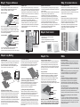
Step 3: Insulate & Secure
Step 1: Prepare & Measure
(a) Substrate Preparation
(b) Make a plan
Use a highly polymer modified (flexible) cementitious floor
adhesive suitable for undertile heating systems when
installing the insulation boards and the tiles.
• Always round down your floor area e.g. for a floor area of
2.6m² you will require 2m² of heat mat (to avoid surplus wire)
• Draw a plan of your room with measurements and all floor
fitting objects e.g. cupboards, bath etc. Calculate the free
floor space so you know which size mat or combination of
mats you will need.
• Mark on your plan where your thermostat will go, and
therefore where your matting will start from, and continue
to draw a plan of how your matting will be laid.
• Electrical wiring regulations prohibit thermostats being
installed in bathrooms; if you are using the system in
a bathroom then install the thermostat on an internal wall
outside the bathroom as close to matting power supply
cables as possible.
Wooden subfloors:
Tile
Adhesive
Heat Mat
Sensor/ Protective Tube
Insulation Board
Adhesive
Wooden Floor
All floor boards must be secure, level and fixed firmly with
screws. If not level then use a self-levelling compound or
overlay with WBP plywood. The Heatwave insulation boards
are not a strengthening material and should only be used on
a sound, flat and rigid substrate.
Concrete subfloors:
Bathroom
Example:
Tile
Adhesive
Heat Mat
Sensor/ Protective Tube
Insulation Board
Adhesive
Concrete Floor
(b) Install & Fix
Boards must be installed with flexible powder based tile
adhesive suitable for undertile heating. Use a notched
floor trowel to apply a bed of adhesive to your substrate
(Trowel in one direction to avoid air pockets).
Work a board at a time and firmly press down to ensure
no air pockets. When adhesive is completely dry apply
Heatwave Glass Fibre tape to edges of board
(see picture 2).
please note:
do not install thermostat on
an interior bathroom wall
(picture 1)
(a) Adjust the mat
(c) Stick the mat down
Using your markings on the floor and the mesh, with scissors
carefully cut the mesh at the necessary points; DO NOT cut
the red wire! Ensure the wire is kept 70mm apart for
optimum heat distribution. Refer to the adjustment guide
on the reverse for help on turning the mat.
Working from the thermostat, start to stick the matting down
by removing the printed backing tape from the matting
and firmly pressing down. Secure the sensor with either
tape or tile adhesive, ensure that it does not cross
any heating wires.
350mm
Check the mark on the floor you made for the location of the
sensor (leave enough excess cable to reach the thermostat).
The sensor should be under the mat in the middle of two
heating wires and 350mm into the heated area, although
not directly over heating pipes beneath the floor. A small
channel may be needed in the floor to accommodate the tube
(in heat mat box), which protects the sensor. Thread the
floor sensor through the tube and tape over the end to stop
any adhesive entering.
Measure the room to calculate number of boards. To cut
the boards, simply score through the top layer with a utility
knife and snap. The boards should be installed in a
staggered pattern (see picture 2). Substrate must be clean,
dry and free from dust before installing
Step 2: Heat Control
Step 4: Lay Matting
(b) Prepare for the floor sensor
(a) Plan, Measure & Cut
• Any floor preparation e.g. levelling, reinforcing or laying of
Heatwave Insulation Board (recommended) should be done
prior to marking.
• Mark the floor where permanent objects and the thermostat
are going. Using your plan, roll out the mat
(remember your gloves!) from your thermostat point,
without removing the printed backing tape and mark the
points where the mesh will have to be cut for turning the
mat or where the mesh may have to be removed from the
red wire to be applied loose into narrow areas.
• Draw the planned route on the floor, for any loose wire
sections, maintaining the 70mm spacing. Loose wire can be
fixed in place using Heatwave Glass Fibre Tape
• Plan the location of the heat sensor.
• Select either LCD or Manual thermostat
• Optimum efficiency
• LCD can be programmed for convenience
• Refer to thermostat instructions for fitting and technical
information
The concrete floor should be level and completely cured,
if new. The floor should be clean and dust free.
The floor should be structurally sound and free from damage.
sensor
protective
tube
thermostat
(c) Mark the floor and mat
Sections d-e ESSENTIAL FOR YOUR WARRANTY
(d) Connecting up (By the Electrician)
Install the Heatwave thermostat as per the instructions in
its box and run the power lead through the electrical
protective casing/conduit (not supplied) up the wall,
with the floor sensor, to the thermostat.
(e) Testing the mat (By the Electrician)
Test the mat and sensor with a multi-meter, check the
readings with the data tables on the relevant instructions
and write this data on the warranty application form.
Before tiling, turn on the system and run for approx 10mins
to ensure the wire heats evenly.
The wire is tough enough to withstand light foot traffic but
plastic sheeting or cardboard should be overlaid if the mat
will be exposed for any period of time to protect the wire
from being damaged by foreign objects or being dislodged
from the mesh.
(picture 2)
Step 5: Tile
FAQs
Using self-levelling compound:
A flexible tile adhesive suitable for under floor heating must
be used. This option gives you a smooth flat base to tile
onto whilst protecting the wire when tiling. Simply mix the
compound and pour over the mat to a depth that covers the
wire making sure there are no air bubbles or voids. Allow to
fully cure and then tile.
Is there a guarantee?
There is a 10 year guarantee on the mat and 2 year on the
thermostat. To validate your warranty the necessary form
must be filled in and sent to us, which can be found in the
Heat Mat or Thermostat box.
Using tile adhesive:
A flexible powder based tile adhesive that is suitable for
undertile heating must be used. Working on a small area
at a time, with a rubber backed trowel apply a layer of
adhesive over the heat mat ensuring complete coverage
of the wire with no air pockets and voids, allow this
layer to set, apply a second layer of adhesive with a
suitable notched trowel (preferably plastic) and apply the tiles.
Tiles
Notched adhesive
Covering layer
of adhesive
Heatwave mat
IMPORTANT: ENSURE THAT THE TILE ADHESIVE AND
GROUT IS FULLY CURED AND DRY BEFORE TURNING
ON THE HEATING SYSTEM FOR THE FIRST TIME. READ
MANUFACTURERS GUIDELINES FOR DRYING TIMES.
Can this heating system be used under laminate/wooden
floors?
Homelux Heatwave system has been specifically designed
for under tile applications and is not recommended for
under real wood, laminate or carpet floor coverings.
Is it safe?
All electrical components in the Heatwave system have
the CE mark. This mark demonstrates that the product
has been tested and conforms to the strict regulations
and standards set out in European market for customer
safety. The mat also conforms to the IEE wiring regulations.
Can I install it myself?
Yes the Heatwave mat is very easy to install, but the route
of the mat and position of the thermostat must be carefully
planned before you start. A fully qualified electrician is
required to make the electrical connections to the thermostat.
Why can’t I turn my heating on as soon as the tiles
are down?
If you turn on the heating system before the tile adhesive
or grout are fully cured and dry, the moisture will be forced
out too quickly and cracks may occur. If you have a concrete
substrate then this must also be completely dry before the
heating mat is installed.
Installation advice
• All electrical wiring must be done by a fully qualified
electrician and in accordance with the current IEE
wiring regulations in order to validate product warranty.
• The Heatwave Insulation Board must be installed if you have
a wooden substrate. It is also recommended with concrete
substrates to optimise efficiency and reduce warming times
(up to 50% more thermally efficient).
• Always round down your floor space area e.g. 2.6m² of floor
will require 2m² of matting (To avoid surplus matting).
• Never overlap the mat, always ensure a 70mm spacing
between the wires for optimum heat distribution.
• If there is a matting shortfall in your floor space then
concentrate the heat mat in heavily trafficked areas.
• A Residual Current Device (RCD) should be used with
this system (must be bought separately).
• Floor must be clean and free from dust & dirt
• Never cut the red wire or join two or more mats together in
series, use a junction box.
• Only use scissors when cutting the mesh.
• The wire is tough but extra care must be taken when using
sharp objects near the mat. A plastic trowel is advisable.
• Check your system with a multi-meter before tile installation.
• Ensure your tile adhesive is suitable for use with undertile
heating e.g. highly polymer modified (flexible).
• Your substrate and floor covering, e.g. tile adhesive or
screed, must be completely dry before switching on your
system for the first time.
• Wear gloves when handling the mat (to avoid irritation to skin).
• Take care when tiling to ensure you do not dislodge or
damage the wire from the mesh mat.
This Box Contains
• The insulation board is not suitable for floor strengthening
and structural reinforcing.
• Matting and Insulation Board should not be passed under
permanent fixings e.g. bath, toilet etc.
• Do not store objects on top of the matting during installation
e.g. tiles.
• Remove old floor coverings
Installation Checklist
1x Heatwave Mat
1x Protective tube
Warranty Information
Other Homelux Heatwave
Products Required
� Homelux Heatwave mat (with supplied protective tube)
� Homelux Thermostat (LCD or Manual)
� Temperature Sensor Cable (supplied in Thermostat box)
Heatwave Glass
Fibre Tape
� Homelux Heatwave Insulation Board
� Homelux Heatwave Glass Fibre Tape
� Multi-meter*
Heatwave
Insulation Board
� Residual Current Device (RCD) (recommended 30 mA)*
� Electrical trunking or conduit to house power lead*
� Electrical back box and junction box (if required)*
� Measuring tape and marker pen*
� Scissors*
� Gloves*
Heatwave
Thermostat
(LCD or Manual)
� Junction Box (required if joining multiple heat mats)*
Instruction
Manual
U N D E R T I L E
H E A T I N G
*not sold as part of the Homelux Heatwave System
H E A T I N G
Please Note: the above products are sold separately
Technical Data
Adjusting the mat
U N D E R T I L E
or
• Don’t worry if your floor plan is not completely square the
matting can be easily adapted and shaped but remember
DO NOT cut the red wire!
• Loose wire can be fixed in place using Heatwave Glass
Fibre Tape.
remove & reposition
Heat Mat Technical Data
cut
cut
mesh mesh
1
Mat
Watts
Ohms
Amps
Voltage
2m2
300
192
1.250
240
3m2
450
128
1.875
240
4m2
600
96
2.500
240
5m2
750
77
3.125
240
Resistance tolerance: ±5%
If you have any problems with Homelux
Heatwave products please contact us:
Postal Address
Homelux Heatwave
Airfield Industrial Estate,
Ashbourne, Derbyshire DE6 1HA, UK
key
thermostat
2
junction box
turn
Free Technical Helpline
0800 707 6361
E-mail
[email protected]
Conductor Insulation: Teflon FEP
Sheath Insulation Material: Teflon
Core conductor material: Nickel Copper Alloy
Metallic braid material: Tinned - Copper
The Heatwave mat conforms to the IEE Wiring
Regulations BS7671
1
2
joining multiple heating mats
Please see thermostat or board instructions for relative
technical data.
Insulation Board Technical Data
turn
180°
Specification
Density
Thermal Conductivity
Compressive Strength
Water Absorption
Flammability
Board Weight
U Value
cut
mesh
For information on all our products
visit our website: www.homelux.co.uk
mat 1
mat 2
Value
165kg/m3
0.027 watt/mK
350 (kN/m2)
0.3%
B1
1.3 Kg
2.25 W/m² K