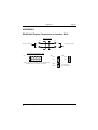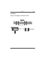
1
SIO-2
2 Channel Serial
Communications Board
User Manual
SIO-2
User Manual
Document Part N°
Document Reference
Document Issue Level
0127-0001
0127-0001.Doc
0.6
Manual covers PCBs identified
SIO-2 Rev. C
All rights reserved. No part of this publication may be reproduced, stored in any retrieval system, or
transmitted, in any form or by any means, electronic, mechanical, photocopied, recorded or otherwise,
without the prior permission, in writing, from the publisher. For permission in the UK contact Blue Chip
Technology.
Information offered in this manual is correct at the time of printing. Blue Chip Technology accepts no
responsibility for any inaccuracies. This information is subject to change without notice.
All trademarks and registered names acknowledged.
Blue Chip Technology Ltd.
Chowley Oak, Tattenhall
Chester, Cheshire
CH3 9EX.
Telephone : 01829 772000 Facsimile : 01829 772001.
Amendment History
Issue
Level
0.5
0.6
Issue
Date
12.05.89
Author
L.P.
SEJ
Amendment Details
First approved issue.
Update window front cover and logo. See
ECN 98/083
Contents
OUTLINE DESCRIPTION .................................................................. 1
1.0 SPECIFICATIONS ....................................................................... 2
1.1 Electrical Specification ............................................................. 2
1.2 Physical Specification .............................................................. 2
Electromagnetic Compatibility (EMC)............................................. 3
EMC Specification ......................................................................... 4
2.0 START-UP GUIDE ....................................................................... 5
2.1 Computer Type ........................................................................ 5
2.2 Backing up the Software Disk................................................... 5
2.3 Selecting the Correct Comms Port Addresses .......................... 6
2.4 Installing the card ..................................................................... 7
2.5 Making the Right Connections.................................................. 8
2.6 The Software Disk.................................................................... 8
3.0 CONNECTING CHANNEL A AND B ............................................ 9
3.1 Connecting to a Serial Printer................................................... 9
3.2 Connecting to a Modem ........................................................... 9
3.3 Connecting to Another SIO-2 Card ......................................... 10
3.4 Connecting a Mouse............................................................... 10
4.0 CHANNEL B ALTERNATIVE INTERFACES............................... 11
4.1 RS422 Full Duplex Mode ....................................................... 11
4.2 RS485 Half Duplex Mode....................................................... 11
4.3 RS485 Multi-Drop Network Mode ........................................... 12
4.4 20 Milliampere Current Loop Mode......................................... 12
5.0 THE SIO-2 AND SOFTWARE .................................................... 13
6.0 COMMERCIAL DATA ACQUISITION PACKAGES .................... 13
APPENDIX A ................................................................................... 15
Blue Chip Technology SIO-2 Rev C ............................................. 15
APPENDIX B ................................................................................... 16
Standard Port Allocations for PC Serial........................................ 16
Ports on LKA or LKB .................................................................... 16
APPENDIX C ................................................................................... 17
Blue Chip Technology Ltd.
01270001.doc
Contents
Standard Port Allocations for PC Serial........................................ 17
Ports on LKA or LKB .................................................................... 17
APPENDIX D ................................................................................... 18
Channel A RS232 Only ................................................................ 18
APPENDIX E ................................................................................... 19
A D25 Pin to D9 Pin Adapter DTE................................................ 19
APPENDIX F.................................................................................... 20
Channel B RS232/422/485/Current Loop...................................... 20
APPENDIX G ................................................................................... 21
Channel B R232 Full Duplex Mode .............................................. 21
APPENDIX H ................................................................................... 22
Connecting Another DTE Device to the SIO-2 Channel B A Null
Modem Cable .............................................................................. 22
APPENDIX I..................................................................................... 23
Channel B 20mA Current Loop Mode........................................... 23
APPENDIX J .................................................................................... 24
Current Loop Full Duplex Connection to Another SIO-2 ............... 24
APPENDIX K ................................................................................... 25
SIO-2 Current Loop Half Duplex Point to Point Connection to
Another SIO-2.............................................................................. 25
APPENDIX L.................................................................................... 26
Channel B RS422/485 Full Duplex Mode ..................................... 26
APPENDIX M................................................................................... 27
Channel B RS422 Full Duplex Connections ................................. 27
to Another SIO-2 .......................................................................... 27
APPENDIX N ................................................................................... 28
Channel B RS485 Half Duplex Mode ........................................... 28
(Multi Drop Mode) ........................................................................ 28
APPENDIX O ................................................................................... 29
01270001.doc
Blue Chip Technology Ltd.
Contents
RS485 Half Duplex Connections to Another SIO-2....................... 29
APPENDIX P ................................................................................... 30
RS485 Multidrop Network up to 32 SIO-2 Cards........................... 30
can be Connected ........................................................................ 30
APPENDIX Q ................................................................................... 31
Interrupt Link Setting for Channels A and B.................................. 31
APPENDIX R ................................................................................... 32
PC/XT/AT Port Map ..................................................................... 32
I/O Address Map .......................................................................... 32
APPENDIX S ................................................................................... 33
PC/XT Interrupt Map .................................................................... 33
APPENDIX T.................................................................................... 34
AT Interrupt Map .......................................................................... 34
APPENDIX V ................................................................................... 35
SIO2TEST.BAS Test Connectors................................................. 35
APPENDIX W .................................................................................. 36
Current Loop Simplex Connections to Another SIO-2................... 36
Overview ..................................................................................... 37
Blue Chip Technology Ltd.
01270001.doc
Outline Description
Page 1
OUTLINE DESCRIPTION
The SIO-2 card allows serial communications between computers, printers,
plotters, screen, PID controllers, instruments and any other device with a serial
interface.
The frist channel is RS232 with programmable baud rate and word format. The
second channel is link selectable as either RS232, RS422/485 (full duplex, half
duplex, multi-drop) or 20mA current loop. This gives compatibility with most
standard serial interchange formats.
The SIO-2 is designed to provide a flexible solution to the problems of
interfacing a PC or compatible with the following standards:
EIA RS232/V24 full or half duplex
EIA RS422 full duplex
EIA RS485 full duplex multi-drop
EIA RS485 half duplex multi-drop
20 Milliampere current loop full duplex
There are two channels designated A and B.
Channel A provides a normal RS232 type comms port and is connected to a 9
pin Cannon D range connector on the rear panel.
The pin out of this connector is to IBM 9 pin Serial standard and id configured
as s DTE device.
Channel B provides a normal RS232 interface on the standard pins of a 25 way
D connector but can also be selected to provide current loop, RS422 and RS485
operation which all appear on different pin outs to provide some protection from
incorrect operation of the card. Channel B is also configured as a DTE device.
A full set of connection details for ever mode of operation appears in the
Appendix.
If installing the SIO-2 card in an Amstrad 1512 or 1640 it may be necessary to
remove the bottom retaining screw on the 25 way D type connector. This is due
to a non-IBM standard back panel on the Amstrad.
Blue Chip Technology Ltd.
01270001.doc
Page 1
Page 2
Specifications
1.0
SPECIFICATIONS
1.1
Electrical Specification
Number of Channels
Interface Standards
Power requirement
Power Dissipation
1.2
5V D.C. @ 150mA
500mW
Physical Specification
Height
Width
Depth
Page 2
2
Channel A RS232
Channel B RS232
RS422
RS485
20mA Loop
107mm
15mm
132mm
01270001.doc
Blue Chip Technology Ltd.
Specifications
Page 3
Electromagnetic Compatibility (EMC)
This product meets the requirements of the European EMC Directive
(89/336/EEC) and is eligible to bear the CE mark.
It has been assessed operating in a Blue Chip Technology Icon industrial PC.
However, because the board can be installed in a variety of computers, certain
conditions have to be applied to ensure that the compatibility is maintained. It
meets the requirements for an industrial environment (Class A product) subject
to those conditions.
• The board must be installed in a computer system which provides screening
suitable for the industrial environment.
• Any recommendations made by the computer system manufacturer/supplier
must be complied with regarding earthing and the installation of boards.
• The board must be installed with the backplate securely screwed to the
chassis of the computer to ensure good metal-to-metal (i.e. earth) contact.
• Most EMC problems are caused by the external cabling to boards. It is
imperative that any external cabling to the board is totally screened, and that
the screen of the cable connects to the metal end bracket of the board and
hence to earth. It is recommended that round screened cables with a braided
wire screen are used in preference to those with a foil screen and drain wire.
Use metal connector shells which connect around the full circumference of
the screen; they are far superior to those which earth the screen by a simple
“pig-tail”. Standard ribbon cable will not be adequate unless it is contained
wholly within the cabinetry housing the industrial PC.
• Ensure that the screen of the external cable is bonded to a good RF earth at
the remote end of the cable.
Blue Chip Technology Ltd.
01270001.doc
Page 3
Page 4
Specifications
Failure to observe these recommendations may invalidate the EMC
compliance.
Warning
This is a Class A product. In a domestic environment this
product may cause radio interference in which case the user may
be required to take adequate measures.
EMC Specification
A Blue Chip Technology Icon industrial PC fitted with this card meets the
following specification:
Emissions:
EN 55022:1995
Radiated
Conducted
Immunity:
Page 4
Class A
Class A & B
EN 50082-2:1995 incorporating
Electrostatic Discharge
IEC 801-2:1991
Performance Criteria A
Radio Frequency Susceptibility
ENV 50140:1993
Performance Criteria A
Fast Burst Transients
IEC 801-4:1988
Performance Criteria A
01270001.doc
Blue Chip Technology Ltd.
Start-up Guide
2.0
START-UP GUIDE
2.1
Computer Type
Page 5
The SIO-2 Communications card is designed to work with all correctly
engineered PC compatible computers that can provide one standard 8 bit IBM
PC compatible I/O slot.
If your machine has two processor clock speed options we suggest that you
perform the installation tests of the SIO-2 with the machine in slow speed
mode.
Once correct operation of the card has been established the perform the same
tests at the higher clock rate.
Unfortunately, although Blue Chip Technology makes every effort to test its
products in a wide range of machines, we cannot guarantee that every so called
“PC compatible” has correct I/O slot timing.
Some of the latest 80386 based machines have a facility in their CMOS RAM
set-up program to adjust the number of wait states used by the machine when
accessing the I/O slot.
2.2
Backing up the Software Disk
The SIO-2 card has been supplied with a floppy disk containing software
demonstrations and example drivers for your use.
It is important that you make an immediate backup of this disk and store it in a
suitably cool dry place.
The disk is not copy protected in any way and you are free to make as many
backup copies as you like for your own departments use.
The disk can be copied onto blank floppy diskette of the same type with the MSDOS command DISKCOPY A: A: on a single drive, or DISKCOPY A: B: on a
twin drive machine.
Blue Chip Technology Ltd.
01270001.doc
Page 5
Page 6
Start-up Guide
If you wish to copy the files to a fixed disk (normally drive C) use the command
MD\SIO-2 to make a suitable directory on drive C:, type CD\SIO-2 followed by
a carriage return, put the SIO-2 floppy disk in drive A: and type COPY A:*.*C:
followed by a carriage return.
This will copy all the files from the SIO-2 disk into the correct directory on
drive C:.
2.3
Selecting the Correct Comms Port Addresses
before placing the SIO-2 into your computer I/O slot it is necessary to establish
and set the correct addresses in the PC port map for the card to use.
The Sio-2 has two channels each of which required a different address to be set.
Channel A is connected to the 9 way D type connector on the back panel and
provides 1 standard PC serial comms port.
The address for channel A is controlled bu the mini-dip header LKA on the
upper left hand side of the board.
Channel B is connected to the 25 way D type connector on the back panel and
provides 1 serial port which can work as a normal PC serial comms port in
RS232 and current loop modes or as a special comms port on RS422//485
modes.
The port address for channel B is controlled by the mini-dip header LKB on the
lower left hand side of the board.
Appendices B and C give example link settings for the normal IBM PC serial
ports COM1 and COM2 plus the usual ports unofficially allocated by software
and hardware manufacturers to COM3-COM8.
Page 6
01270001.doc
Blue Chip Technology Ltd.
Start-up Guide
Page 7
The SIO-2 card is normally issued from the factory with channel A set to
COM1 and channel B set to COM2. It is quite likely that your computer
will already have at least one serial port built into it; if so then this will
usually be occupying the COM1 port address.
There are two solutions to this contention problem:
i.
ii.
Disable the COM1/COM2 on your PC. See your PC manual for
instructions.
Change the I/O port addresses(and possibly interrupts) on the SIO-2
card. See Appendices B, C and Q. Ensure that no other cards or
system devices are set to the same port address or interrupt. Multiple
SIO-2 cards can use the same interrupts provided that the software is
written to support this.
Extra mini-dip green links are provided with your package to enable other
address selections to be set.
2.4
Installing the card
If this is the first time that you have installed a peripheral card in your PC, you
should refer to the instructions in the hardware guide supplied with your
machine for information on how to remove the cover and install devices into the
I/O channel slot.
The SIO-2 may be placed in any available slot of your PC compatible computer
provided that there is no restriction placed upon the slot be the manufacturer of
the machine.
Blue Chip Technology Ltd.
01270001.doc
Page 7
Page 8
2.5
Start-up Guide
Making the Right Connections
Channel A of the SIO-2 is intended for RS232 DTE operation only.
Channel B is supplied with its links set for RS232 DTE operation. If you wish
to use any of the other options on the channel B then you should follow the link
position and connection diagrams supplied in the Appendix and read the
appropriate section of the manual.
The type of connection you will need to make to channel B of the SIO-2 will
depend upon the interface on the peripheral device you wish to connect to.
2.6
The Software Disk
The card can be used as COM1 or COM2 in full duplex RS232/RS422 and
current loop modes from most existing software, but the RS485 half duplex
mode requires the user to program the board to switch transmission on and off
and for this mode of knowledge of programming in any of the PC languages is
required.
The software disk supplied with the SIO-2 contains a number of example ways
of driving the card from various languages.
Page 8
01270001.doc
Blue Chip Technology Ltd.
Connecting Channel A and B
3.0
Page 9
CONNECTING CHANNEL A AND B
Channel A appears on the 9 way D connector on the rear panel as standard IBM
PC AT style RS232 serial port.
Channel B appears on the 25 way D connector on the rear panel as a standard
IBM PC style RS232 and current loop port and also has RS422 and RS485
capability.
Both channels can be used to connect various peripherals such as printers,
modems and mouse type pointing devices.
3.1
Connecting to a Serial Printer
When IBM designed the PC they considered it to be a data TERMINAL and so
the serial port design is treated as a TERMINAL or DTE device. The
consequence of this is that to connect it to another peripheral such as a printer
you must reverse the signals between the two devices.
When connecting a serial printer it is necessary to remember to connect the
printer busy line (normally pin 20 on the 25 way D connector on the printer) to
the DSR, CTS and DCD connections on the appropriate connector on the PC.
The wiring diagram for a suitable cable appears in Appendix H.
3.2
Connecting to a Modem
The connections for this type of equipment should normally be direct signal to
signal and in the case of the WS4000 the following pins will make the modem
behave correctly.
Blue Chip Technology Ltd.
01270001.doc
Page 9
Page 10
Connecting Channel A and B
25 way D connector
Pin
Pin
Pin
Pin
Pin
2
3
8
20
7
Transmit data
Receive data
Data carrier detect
Data terminl ready
Digital ground
TX
RX
DCD
DTR
If you wish to use a modem on channel A the details of a D25 to D9 converter
cable appear in Appendix E. Alternatively, you can create a special direct cable
from the information in the pinout details.
3.3
Connecting to Another SIO-2 Card
The null modem cable concept (Appendix H) can be used again for this
connection and it should be remembered that for cable lengths of over 50 feet
another interface such as RS422/485 should be considered.
3.4
Connecting a Mouse
We recommend the Microsoft Serial Mouse for use with the SIO-2. This comes
with an adapter for both D9 and D25 connections. There are other mice on the
market and provided they are designed to work through a standard IBM PC
serial port then they should present no problem.
If you do experience problems, please refer to the supplier of the mouse first
before contacting us.
Blue Chip Technology can supply a complete range of printers, mice, plotters
and external terminals etc. For more details contact our Sales Department.
Page 10
01270001.doc
Blue Chip Technology Ltd.
Channel B Alternative Interfaces
4.0
CHANNEL B ALTERNATIVE INTERFACES
4.1
RS422 Full Duplex Mode
Page 11
To set the SIO-2 for RS422 full duplex mode refer to Appendix L for the
connections and link positions for LKD. Appendix A contains a complete
drawing of the SIO-2 card detailing the locations of the various links on the
board.
It is important to remember to use good quality shielded twisted pair cable for
this interface especially if a high baud rate (i.e. :- greater than 2400) is being
used.
The line drive and receiver interface device used for this mode if the 75176 and
in this mode IC9 transmits data and IC8 receives it.
4.2
RS485 Half Duplex Mode
N.B. Remember when using this mode to fit good quality shielded twisted pair
cable and also to install the links to enable the 100ohm terminating resistors in
the cards at the ends of the cable. See Appendix L.
Communication on a single twisted pair can be achieved with RS485 half
duplex mode.
Appendix N details the link settings and connections for this mode.
IC9 is used alone to provide this interface and consequently it must be switched
from receive to transmit and back again to receive when the user wishes to send
a message.
Blue Chip Technology Ltd.
11
01270001.doc
Page
Page 12
Channel B Alternative Interfaces
The signal to switch the Tx and Rx can be selected as DTR or OUT1 from the
channel BB 164550 device. Link C allows you to select the appropriate signal.
By setting the selected signal to a high state IC9 is put into the Receive mode.
RS485 half duplex is very useful mode of operation for data acquisition and
message switching between PC based equipment Appendix O details how to
connect two SIO-2 cards back to back in this mode.
4.3
RS485 Multi-Drop Network Mode
Appendix P details how to couple up multiple SIO-2 cards to form a multi-drop
network which is capable of communication at distances of up to 1 kilometre
dependent upon baud rate.
Please remember that the protocol for using this mode of operation is totally
dependent upon the user designing software to avoid message collision and
provide some form of packet based addressing system.
N.B. Remember when using this mode to fit good quality shielded twisted pair
cable and also to install the links (LKD5 and LKD6) for the 100ohm
terminating resistors in the cards at the ends of the cable. See Appendix L.
4.4
20 Milliampere Current Loop Mode
Appendix I details the correct link settings and connections for current loop
operation.
IC13 and IC14 provide the driver and receiver for this mode. The pin out of the
current loop mode has been designed to be identical to that used on the IBM PC
serial adapter.
Thus any cable designed to use this interface card should work properly when
plugged into the SIO-2.
Appendix J and K detail the correct connections for full and half duplex
operation in this mode.
Appendix W details the correct connections for simplex operation in this mode.
Page 12
01270001.doc
Blue Chip Technology Ltd.
The SIO-2 and Software
5.0
Page 13
THE SIO-2 AND SOFTWARE
How you drive the SIO-2 depends totally upon the type of application you
propose to use it for. If the card is set-up as COM1 and COM2 then the
channels can be driven from DOS with the exception that half duplex RS485
requires some extra programming in this mode.
It should be remembered that under MS-DOS 3.2 and below there is no software
support provided by the operating system for more than the first two serial ports
on the system (COM1 and COM2).
Other operating systems such as IBM PC-DOS and 386 and PCMOS386 do
allow the user to make use of more than 2 serial ports for the connection of estra
user terminals and other printers etc. and it is expected that OS/2 will do the
same.
Many language compilers have the facility to use add on communications
toolkits such as the Greenleaf comms library for ‘C’ etc.
The card uses the national Semiconductor NS16450N device which is
functionally equivalent to the original Intel 8250 device used on the early PC
serial cards and is the same chip used by most PC manufacturers today.
The floppy disk which accompanies the card contains a number of programs as
examples of how to drive the COM ports from different languages.
There is a file called README.TXT on the disk which details the latest updates
to the programs.
6.0
COMMERCIAL DATA ACQUISITION PACKAGES
The Blue Chip Technology SIO-2 can be used with almost any data acquisition
package that can transmit and receive information directly to and from a PC
serial port, or any package that has driver support for the INTEL 8250 or
National Semiconductor NS164450chip.
The board is installable as a standard serial PORT in the following packages:
Blue Chip Technology SCAN1000
Blue Chip Technology Ltd.
13
01270001.doc
Page
Page 14
The SIO-2 and Software
ASYST by Macmillan Software
Labtech notebook
LOTUS Measure
LOTUS Symphony
Almost any PC based communications package
For more details about these packages and other PC data acquisition software,
please contact Blue Chip Technology.
Whilst every effort has been taken to ensure that the information provided is
accurate, Blue Chip Technology cannot assume responsibility for any errors in
this manual or their consequences. Should any errors in this manual be
detected, the company would greatly appreciate being informed of them. A
policy of continuos product development is operated, resulting in the contents of
this document being subject to change without notice.
Page 14
01270001.doc
Blue Chip Technology Ltd.
Appendix A
Page 15
APPENDIX A
Blue Chip Technology SIO-2 Rev C
Blue Chip Technology Ltd.
15
01270001.doc
Page
Page 16
Appendix B
APPENDIX B
Standard Port Allocations for PC Serial
Ports on LKA or LKB
COM 2
COM 1
3F8 HEX
2F8 HEX
008H
008H
010H
010H
020H
020H
040H
040H
080H
080H
100H
100H
200H
200H
N.B. All links removed
COM 3
COM 4
3E8 HEX
Page 16
2E8 HEX
008H
008H
010H
010H
020H
020H
040H
040H
080H
080H
100H
100H
200H
200H
01270001.doc
Blue Chip Technology Ltd.
Appendix C
Page 17
APPENDIX C
Standard Port Allocations for PC Serial
Ports on LKA or LKB
COM 6
COM 5
280 HEX
288 HEX
008H
008H
010H
010H
020H
020H
040H
040H
080H
080H
100H
100H
200H
200H
COM 7
COM 8
290 HEX
298 HEX
008H
008H
010H
010H
020H
020H
040H
040H
080H
080H
100H
100H
200H
200H
(N.B. ALL LINKS VIEWED WITH
CONNECTORS ON RHS)
Blue Chip Technology Ltd.
17
01270001.doc
Page
Page 18
Appendix D
APPENDIX D
Channel A RS232 Only
D9 Connections
5
9
Digital Ground
RI
DTR
CTS
TX Output
RTS
RX Input
DSR
DCD
1
Page 18
01270001.doc
6
Blue Chip Technology Ltd.
Appendix E
Page 19
APPENDIX E
A D25 Pin to D9 Pin Adapter DTE
D25 And D9 Pin Connections
D25
D9
DCD
DCD
8
1
3
2
2
3
20
4
7
5
6
6
4
7
5
8
22
9
RX Input
RX Input
TX Output
TX Output
DTR
DTR
Digital Ground
Digital Ground
DSR
DSR
RTS
RTS
CTS
CTS
RI
RI
Blue Chip Technology Ltd.
19
01270001.doc
Page
Page 20
Appendix E
APPENDIX F
Channel B RS232/422/485/Current Loop
D25 Connections
13
25
RCLR (Current Loop -)
TCLR (Current Loop -)
RI (RS232)
TCLD (Current Loop -)
DCD (RS232)
DTR (RS232)
Digital Ground
DSR (RS232)
RCLD (Current Loop +)
CTS (RS232)
B
RTS (RS232)
A
Full/Half Duplex TX
Full Duplex RX
RX INPUT (RS232)
B
TX Output (RS232)
RX Full Duplex
A
NC
14
1
Page 20
01270001.doc
Blue Chip Technology Ltd.
Appendix G
Page 21
APPENDIX G
Channel B R232 Full Duplex Mode
D25 Connections
13
25
RI Input
DCD Input
DTR Output
Digital Ground
DSR Input
CTS Input
RTS Output
RX INPUT
TX Output
14
1
Link Positions
LKD
1
Blue Chip Technology Ltd.
21
01270001.doc
2
3
4
5
6
Page
Page 22
Appendix H
APPENDIX H
Connecting Another DTE Device to the SIO-2 Channel B
A Null Modem Cable
D25 Connections
SIO-2
Printer or Second SIO-2
RX Input
TX Output
2
3
3
2
4
4
5
5
6
6
7
7
8
20
20
8
TX Output
RX Input
RTS
RTS
CTS
CS
DSR
DSR
Digital Ground
Digital Ground
DTR
DCD
DCD
DTR
Page 22
01270001.doc
Blue Chip Technology Ltd.
Appendix I
Page 23
APPENDIX I
Channel B 20mA Current Loop Mode
D25 Connections
13
25
RCLR TCLR TX
RX
TCLD +
RCLD +
14
Link Positions
1
LKD
1
LKH
Optional
For Pull-up
On RX
LKJ
Optional
For Pull down
On RX
2
3
4
5
1
LKH
1
2
Optional
For Pull-up
On TX
2
LKJ
1
1
2
Blue Chip Technology Ltd.
23
6
Optional
For Pull down
2
On TX
01270001.doc
Page
Page 24
Appendix J
APPENDIX J
Current Loop Full Duplex Connection to Another SIO-2
1st SIO-2
2nd SIO-2
Non-Isolated (Active) Station
Isolated (Passive) Station
D25 Connections
20mA
Data
XMTR
4100
P2/11
P2/18
P2/7
P2/25
RCVR
4200
Data
XMTR
4100
Data
20mA
P2/25
RCVR
4200
Data
P2/9
P2/7
P2/11
Link Settings for 1st SIO-2
LKH
LKD
Page 24
1
2
1
2
3
4
5
Link Settings for 2nd SIO-2
LKH
LKD
6
2
1
01270001.doc
1
2
3
4
5
6
Blue Chip Technology Ltd.
Appendix K
Page 25
APPENDIX K
SIO-2 Current Loop Half Duplex Point to Point
Connection to Another SIO-2
1st SIO-2
2nd SIO-2
Non-Isolated (Active) Station
Isolated (Passive) Station
D25 Connections
20mA
Data
XMTR
4100
P2/11
P2/18
P2/7
P2/25
RCVR
4200
Data
XMTR
4100
Data
P2/25
Data
RCVR
4200
P2/9
P2/18
P2/11
Link Settings for 1st SIO-2
LKD
LKH
2
1
2
3
4
5
6
Blue Chip Technology Ltd.
25
Link Settings for 2nd SIO-2
1
LKH
LKD
1
2
1
2
3
01270001.doc
4
5
6
Page
Page 26
Appendix L
APPENDIX L
Channel B RS422/485 Full Duplex Mode
D25 Connections
Link Positions
LKD
13
25
1
2
3
4
5
6
(N.B. LKD 5/6 CAN BE FITTED TO
ENABLE THE 100R TERMINATOR
RESISTORS IN THE RX AND TX LINES
RESPECTIVELY)
LKE
FUL
HLF
N.B. LKC NOT APPLICABLE
B
TX Twisted Pair
A
B
RX Twisted Pair
A
14
1
Page 26
01270001.doc
Blue Chip Technology Ltd.
Appendix M
Page 27
APPENDIX M
Channel B RS422 Full Duplex Connections
to Another SIO-2
D25 Connections
SIO-2
SIO-2
A
16
Sheilded Twisted Pair
14
A
Sheilded Twisted Pair
B
17
15
A
16
14
B
A
Sheilded Twisted Pair
Sheilded Twisted Pair
17
B
B
15
Link Positions
LKD
(NB: FIT LKD 5 AND/OR 6 TO ENABLE
100OHM RESISTORS R3 AND R4 TO
TERMINATE CIRCUIT).
1
Blue Chip Technology Ltd.
27
2
3
4
5
6
01270001.doc
Page
Page 28
Appendix N
APPENDIX N
Channel B RS485 Half Duplex Mode
(Multi Drop Mode)
D25 Connections
Link Positions
LKD
13
1
25
2
3
4
5
6
LKE
FUL
HLF
LKC
OUT1
OUT1
DTR
DTR
FIT TO SELECT SWITCHING SIGNAL
B
TX Twisted Pair
A
14
1
Page 28
01270001.doc
Blue Chip Technology Ltd.
Appendix O
Page 29
APPENDIX O
RS485 Half Duplex Connections to Another SIO-2
D25 Connections
SIO-2
SIO-2
A
16
16
A
17
B
Sheilded Twisted Pair
Sheilded Twisted Pair
B
17
Link Positions On Both SIO-2 Cards
LKD
LKE
1
2
3
4
5
LKC
FUL
OUT1
HLF
DTR
6
(NB: FIT LINK LKD 5 TO ENABLE 100 OHM TERMINATING
RESISTOR IN R4 AT EACH END OF CIRCUIT)
OUT1
DTR
Blue Chip Technology Ltd.
29
01270001.doc
FIT TO SELECT
SWITCHING SIGNAL
Page
Page 30
Appendix P
APPENDIX P
RS485 Multidrop Network up to 32 SIO-2 Cards
can be Connected
D25 Connections
Station 1
Station 1
A
A
16
16
16
B
B
B
etc
17
17
17
Use Shielded Twisted Pair Cable
Link Positions All Both SIO-2 Cards
LKD
(FIT LKD 5 TO
ENBLE R4 AT EACH
END OF CABLE
1
2
LKE
FUL
3
4
5
6
LKC
OUT1
OUT1
DTR
DTR
(OUT1/DTR ON CHANNEL B
SWITCHES THE RS485
CIRCUIT ON AND OFF).
FIT TO SELECT
SWITCHING SIGNAL
HLF
Page 30
01270001.doc
Blue Chip Technology Ltd.
Appendix Q
Page 31
APPENDIX Q
Interrupt Link Setting for Channels A and B
D25 Connections
Station 1
Station 1
A
A
16
16
16
B
B
B
etc
17
17
17
Use Shielded Twisted Pair Cable
Link Positions All Both SIO-2 Cards
LKD
(FIT LKD 5 TO
ENBLE R4 AT EACH
END OF CABLE
1
2
3
4
5
6
LKE
FUL
LKC
OUT1
OUT1
DTR
DTR
(OUT1/DTR ON CHANNEL B
SWITCHES THE RS485
CIRCUIT ON AND OFF).
FIT TO SELECT
SWITCHING SIGNAL
HLF
Blue Chip Technology Ltd.
31
01270001.doc
Page
Page 32
Appendix R
APPENDIX R
PC/XT/AT Port Map
I/O Address Map
Address
000-01F
02-03F
040-05F
060-06F
070-07F
080-09F
0A0-0BF
0F0
0F1
0F8-0FF
1F0-1F8
200-207
278-27F
2F8-2FF
300-31F
360-36F
378-37F
380-38F
3A0-3AF
3B0-3BF
3C0-3CF
3D0-3DF
3F0-3F7
3F8-3FF
Page 32
DMA controller 1, 8237A-5
Interrupt controller 1, 8259A
Timer, 8254
Keyboard controller, 8742; control port B
RTC and CMOS RAM, NMI Mask (Write)
DMA Page Register (Memory Mapper)
Interrupt controller 2, 8259
Clear NPX (80287) busy
Reset NPX, 80287
Numeric Processor Extension, 80287
Hard disk drive controller
Reserved
Reserved for Parallel Printer Port 2
Reserved for Serial Port 2
Reserved
Reserved
Parallel Printer Port 1
Reserved for SDLC Communications, Bisynchronous 2
Reserved for Bisynchronous 1
Reserved
Reserved
Display Controller
Diskette Drive Controller
Serial Port 1
01270001.doc
Blue Chip Technology Ltd.
Appendix S
Page 33
APPENDIX S
PC/XT Interrupt Map
Number
Usage
NMI
Parity
0
1
2
3
Timer
Keyboard
Reserved
Asynchronous Communications
(Secondary)
SDLC Communications
Asynchronous Communications
(Primary)
SDLC Communications
Fixed Disk
Diskette
Parallel printer
4
5
6
7
Blue Chip Technology Ltd.
33
01270001.doc
Page
Page 34
Appendix T
APPENDIX T
AT Interrupt Map
Level
Microprocessor NMI
Function
Parity or I/O Channel Check
Interrupt Controllers
CTLR 1 CTLR 2
IRQ 0
IRQ 1
IRQ 2
Timer Output 0
Keyboard (Output Buffer Full)
Interrupt from CTLR 2
IRQ 8
IRQ 9
IRQ 10
IRQ 11
IRQ 12
IRQ 13
IRQ 14
IRQ 15
IRQ 3
IRQ 4
IRQ 5
IRQ 6
IRQ 7
Page 34
Realtime Clock Interrupt
Software Redirected to INT 0AH (IRQ 2)
Reserved
Reserved
Reserved
Coprocessor
Fixed Disk Controller
Reserved
Serial Port 2
Serial Port 1
Parallel Port 2
Diskette Controller
Parallel Port 1
Appendix S
01270001.doc
Blue Chip Technology Ltd.
Appendix V
Page 35
APPENDIX V
SIO2TEST.BAS Test Connectors
Test connectors to operate with SIO2TEST.BAS can be made up by making the
following links on dummy connectors.
D9
2-3
4-6
7-8
Blue Chip Technology Ltd.
35
D25
2-3
4-5
6-8-20
7-25
14-16
15-17
18-11
01270001.doc
Page
Page 36
Appendix W
APPENDIX W
Current Loop Simplex Connections to Another SIO-2
1st SIO-2
2nd SIO-2
Non-Isolated (Active) Station
Isolated (Passive) Station
D25 Connections
20mA
Data
XMTR
4100
P2/11
P2/18
P2/7
P2/25
RCVR
4200
Link Settings for Both SIO-2 Boards
LKH
LKD
1
Page 36
1
2
2
3
4
5
6
01270001.doc
Blue Chip Technology Ltd.
Data
Appendix X
Page 37
Overview
RS422/RS485
Most people have heard of RS232C as an interface standard used in computer
communications. The RS232C standard has been successful in uniting the
industry to a common interface, but it suffers from several limitations:
1.
2.
3.
Data transmission rate.
Transmission distance.
The need to connect the ground together (unbalanced circuits).
RS422 was established in 1975. It overcomes the above problems and provides
a fast, reliable balanced interface. Data transmission rate is improved from 38.4
Kilobaud up to 10 Megabaud; the transmission distance is increased from 15
metres to 1 Kilometre and the circuit operates in a differential mode and does
not require a common ground connection.
Note: The transmission rate and distance are mutually exclusive.
The natural progression for RS422 was for it to grow into a network
communications medium. As far as point to point communications are
concerned (see figure 1.) RS422 is a success due to the possible high speed and
long distances. However, when the true “bus topology” network (figure 2.) was
considered the standard RS422 transceivers could not cope with the possibilities
of more than one transmitter being active at any one time.
Figure 1
Computer A
Blue Chip Technology Ltd.
37
Computer B
01270001.doc
Page
Page 38
Appendix x
Figure 2
Computer
1
Computer
2
Computer
3
Up to 32
If this situation did occur, the RS422 drivers would probably be irreparably
damaged. To overcome this the RS485 standard was established. This allows
for the possibility of a transmission “collision” from any two computers without
any damage occurring. The RS485 is now the industry standard for low cost
Collision Sensing Multiple Access networks (CSMA) and the most popular
device for implementing this circuitry is the 75176 transceiver as used on the
Blue Chip Technology SIO-2.
The electrical details of the RS485 standard are:
1.
Differential Drive - the two outputs are driven to opposite polarities at
any one time. The maximum difference between the output pins at any
time is 6 volts and the minimum is 2 volts.
2.
The input can accept up to +/- 12 volts without any damage being
sustained.
3.
The ability to drive up to a total of 32 transceivers connected at any one
instant (further transceivers can be accepted by using repeaters).
4.
The receiving sensitivity is 200 millivolts difference between the inputs
pins.
Page 38
01270001.doc
Blue Chip Technology Ltd.
Appendix X
5.
Page 39
-7 volts to + 12 volts bus common mode range permits a ground
difference of +/- 7 volts between devices on the bus.
Considerations
1.
It is recommended that termination is applied to the devices at each
end of the bus. This termination is typically 100 ohms (this is provided
on the SIO-2 card and can be effected by fitting links on the card; see
the manual), although it depends on the characteristic impedance of
the cable being used.
RT
An alternative method of termination can be implemented as below:
+ve
0v
This can be effective under certain conditions but does provide a path
between the power rails on the devices.
Blue Chip Technology Ltd.
39
01270001.doc
Page
Page 40
2.
Appendix x
The layout of the bus topology is subject to a phenomenon known as
“Transmission Line” effects. This can affect the signal strength at
various points on the bus and if the distance from the true bus to the
device is not kept as short as possible there is a distinct chance that
null points (extreme) or low signal strength (more likely) will appear.
Spurs length to be kept
as short as possible
The ideal is where no spur (stub) length exists. This can be achieved
by connecting the bus and the joining device at the same point.
3.
Length of cable is determined by the transmission rate e.g.
Maximum Distance
1 Kilometre
100 Metres
10 Metres
Rate
100 Kilobaud
1 Megabaud
10 Megabaud
(Using 24 AWG cable).
4.
Page 40
The cable used can affect the operation of the bus. Typically, it should
present a nominal characteristic impedance of 100 ohms to frequencies
greater than 100 kilohertz and a DC series loop resistance not
exceeding 240 ohms.
01270001.doc
Blue Chip Technology Ltd.
Appendix X
Page 41
Whether the cable is twisted or not, screened or not, can affect the
operation. Obviously, by screening the cable the noise immunity can
be increased but you should consider:
a.
Where is the screen attached to - it is not advisable to connect
the screen up to all devices (remember RS232 ?).
b.
The cable to cable crosstalk within a sheath will increase.
c.
The cable tray capacitance will increase and if excessive
(depends on length of cable and value/foot) can affect
performance.
The above should be considered before a network is
implemented.
5.
There should not be more than 7 volts difference between any two
devices’ ground potential on the bus. Beyond 7 volts the common
mode range will be exceeded and the devices will not operate correctly.
One way to operate under these conditions is by introducing an
isolating transformer in the output circuitry of the transceivers.
6.
Problems can be experienced when implementing a software protocol
on a 2 wire bus.
As we have stated before no two transceivers can transmit at the same time.
Therefore, a mechanism must exist so that each device knows when it can
transmit freely.
The most common way of operation is the “Master Slave” method. This is
where one device on the network is deemed to be the Master and this device
initiates all transmissions by communicating with each if the other devices in
turn and offering it an opportunity to transmit. This provides a relatively
simple solution but means that the Master will have a high overhead in
controlling the network. Also devices needing to communicate to devices other
than the Master carry a larger overhead and an additional software
complication.
Blue Chip Technology Ltd.
41
01270001.doc
Page
Page 42
Appendix x
A more sophisticated protocol is the “Token Ring” method which works by each
device knowing which device is next on the bus (ID number, not by physical
location) and taking directly to it.
The communication occurs between each adjacent pair of devices and can
improve the flexibility of the network but is more difficult to implement
especially where devices can be switched on or off at any time.
Current Loop
This method of interfacing has been used for a relatively long time now. It has
a reputation for high integrity in noisy environments and the ability to isolate
the various devices within the loop. Its weakness is usually transmission rate
where 9600 baud is acknowledged as high (although 19200 baud is possible)
and this limits current loop to low speed activities.
The basis of the current loop interface is that rather than a voltage which is
transferred between devices as with RS232, 422 and 485, a current is passed
instead.
This figure shows a typical current loop circuit.
Local
Remote
+ve
+ve
0v
Page 42
01270001.doc
Blue Chip Technology Ltd.
Appendix X
Page 43
A constant current generator provides an output from the local device that is fed
to the external cabling and passes through an LED (light emitting diode) at the
remote device. The current is fed back to the local device and is then switched
on or off to provide to modulation of the current to either produce a MARK or
SPACE bit.
Considerations
1.
If multiple CL devices are connected in a daisy chain arrangement, it
may be necessary to fit by-pass diodes at each station in case the cable
is disconnected.
Station 1
Station 2
+ve
By doing so the current path is ensure at all times regardless of
whether the connection to the station is made or not.
It should be remembered that the positive voltage applied at the current
generator device will limit the number of series diodes (either LED or
conventional).
2.
The capacitance of the cable can affect the CL operation significantly.
The larger the capacitance and length of the cable the lower the
maximum possible transmission rate.
Blue Chip Technology Ltd.
43
01270001.doc
Page
Page 44
3.
Appendix x
Various permutations of pull ups and pull downs can be used
(especially on BCT SIO-2) to provide the current path. Basically
conventional current must flow from a positive voltage to a negative
voltage. This can be achieved in many ways:
Local
Remote
+ve
+ve
0v
Page 44
01270001.doc
Blue Chip Technology Ltd.