1
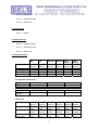
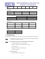
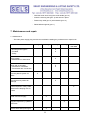
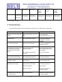
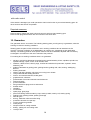
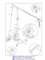
USER’S MANUAL
Introduction
This operating manual should make it easier to learn about the machine and its features.
The operating manual contains important information on operating the machine safely,
correctly and efficiently. Following the instructions helps prevent accidents, unnecessary
repair costs and down time, which extends the machine’s reliability and service life.
The operating manual is yet to be supplemented with instructions pertaining to national laws concerning
accident prevention and environmental protection.
The operating manual must always be accessible on the machine.
Every person working on this machine must read and follow the instructions in the operating manual.
This includes the following areas:
• Operation, including setting-up, troubleshooting, disposal of waste products, product care, disposal of
lubrication and auxiliary products.
• Servicing (maintenance, inspection, repair) and/or
• Transport
In addition to the operating manual and to complying with all national and local regulations concerning
accident prevention, the general technical regulations for safe and correct operation must also be
adhered to.
Table of Contents
1. General Safety Precautions
2. Description of Machine
3. Commissioning
4. Transport
5. Operation
6. Dismantling
7. Maintenance and repair
8. Troubleshooting
9. Accessories
1
10. Guarantee
1. General Safety Precautions
1.1 Warning Labels and Symbols used in this Manual
Danger!
Not following the instructions can result in serious injuries or even
death.
Caution!
Not following the instructions can, under certain conditions, result in
injuries.
Note!
Not following the instructions can result in damage to the machine or
other equipment.
1.2 General Safe Operating Procedures
Danger!
1.2.1 The machine has been manufactured in keeping with the most recent technology and the
recognised safety rules. Nevertheless there may be some risk of a hazard to life and limb of the
user or third persons or impairments of the machine and other real assets respectively.
1.2.2 Use the machine only in good working condition and follow all procedures concerning correct and
safe operation, as outlined in the manual! This applies specifically to malfunctions that can
jeopardise safety!
Danger! 1.2.3 The crane is designed exclusively for the raising and lowering of flat elements.
The flat elements must not exceed a max. wind surface of 0.64 m².
The manufacturers/suppliers accept no responsibility for any damaged caused by
incorrect usage.
Correct usage includes adherence to the operating instructions and the service
and maintenance instructions.
1.3 Organisational Measures
1.3.1 Always keep the operating manual close to the crane and easily accessible
Danger! 1.3.2
Observe and give instruction to observe all laws and regulations concerning
accident prevention and environmental compliance supplementary to this
operating manual!
2
These regulations can, for example, apply to the use of dangerous materials,
personal protective equipment, and road traffic laws.
Danger! 1.3.3
1.3.4
Any personnel working on the crane must read the operating instructions,
especially the chapter on safety precautions, prior to starting work. Reading
them while on the job is too late. This applies in particular to any personnel
only occasionally working on the crane (e.g. set-up and maintenance crews).
Carry out at least occasional spot checks to ensure that personnel are working in a
safe and conscientious manner and adhering to the instructions in the operating
manual!
Caution! 1.3.5
Use personal protective equipment whenever necessary or if required by
regulations!
Danger! 1.3.6.
Observe all safety instructions and danger warnings located on the crane!
Danger! 1.3.7
Make sure that all safety instructions and danger warnings on the crane are always
legible!
Danger! 1.3.8
Stop the crane immediately and notify appropriate office/personnel if there are any
safety-related changes in the crane or its manner of operation!
Danger! 1.3.9
Do not carry out any modifications, extensions or conversions to the crane without
prior permission from the manufacturers/suppliers!
Danger! 1.3.10 Only use original spare parts!
Danger! 1.3.11 Adhere to inspection deadlines as prescribed or specified in the operating
instructions! An annual inspection by a qualified agency (Technical Inspectorate TÜV – or the manufacturers) is mandatory!
1.3.12 The crane must be cleaned thoroughly prior to inspection.
1.3.13 An inspection logbook must be kept for the crane in which the annual inspections
are to be recorded in writing.
1.3.14 All crane models, excl. 300/400 and 300/400 T, must be subjected to an
additional main inspection by an appointed technical Inspectorate (BG, TÜV) every
four years as well as in year 14 and 16 of operation, and afterwards yearly.
Danger! 1.3.15 The main power supply plug must be disconnected prior to carrying out any
maintenance or repair work!
1.4 Qualification and selection of personnel; fundamental responsibilities
Danger! 1.4.1 Personnel being permitted to work on their own on the crane must be over 18 years
of age, instructed in the operation of the crane and have been appointed in writing
with the operation of the crane by the owner.
3
Danger! 1.4.2 Unnecessary loitering on moving parts or within the movement range of the crane is
forbidden!
Danger! 1.4.3 Operating personnel must ensure at all times when moving the crane that they are
not endangering themselves or anyone else.
Danger! 1.4.4 Work on electrical equipment on the machine may only be carried out by a qualified
electrician or by an instructed person under the supervision of a qualified electrician
in compliance with respective regulations for electrical equipment.
Danger! 1.4.5 Personnel undergoing training, apprentices or new employees must be kept under
constant supervision by an experienced operator if working on the machine!
1.5 Safety instructions for specific operating phases
1.5.1 Normal operation
1.5.1.1
Any forms of working that represent a safety risk are forbidden!
Danger! 1.5.1.2 Take steps to ensure that the crane is only used when in a safe and operational
state!
1.5.1.3
Check the crane at least once a shift for visible signs of damage and faults! Any changes
(including any to operation) must be reported at once to the appropriate office/personnel!
If necessary, switch the machine off at once and secure!
Danger! 1.5.1.4 Stop the crane immediately and secure if their are any functional problems!
Rectify any faults immediately!
Danger! 1.5.1.5 The crane must be standing on a clean, horizontal and sound base capable of
bearing the crane. The max. wheel pressure is 14 kN.
Danger! 1.5.1.6 Connecting the crane to the power circuit is forbidden if there is no earth-leakage
circuit breaker (e.l.c.b.) in the power supply line or the distributor box.
Danger! 1.5.1.7 The crane must be taken down if wind force 7 (15 m per sec.) or greater prevails.
Danger! 1.5.1.8 Transporting people on the crane is forbidden!
Danger! 1.5.1.9 Loitering underneath suspended loads is forbidden.
Danger! 1.5.1.10 Only ever use suitable and tested hoisting gear (stone tongs).
1.5.2 Extracurricular work while using the machine, maintenance/repair work as well as
troubleshooting; waste disposal
4
Caution! 1.5.2.1 Adjustment, maintenance and service activities and periods, including details on
exchanging parts/components/assemblies, must be observed as specified in the
operating instructions! This work may only be carried out by qualified technicians!
Caution! 1.5.2.2 Notify operating personnel prior to commencing extracurricular and/or repair work!
Appoint a supervisor!
Danger! 1.5.2.3 If the crane has been turned off completely for maintenance or repair work,
secure it against being turned back on again unexpectedly!
Note 1.5.2.4
Before cleaning the crane with water or other detergents, cover/seal any openings
where water/steam/detergent penetration is not permitted for safety or
functional reasons. This applies in particular to electromotors, switches and plug
connections.
Note 1.5.2.5
Remove the covers/seals again completely when cleaning work is finished!
Danger! 1.5.2.6 Retighten any screw connections which may have come loose during maintenance
and repair work!
Danger! 1.5.2.7 If the removal of protective devices on the machine was necessary for set-up,
maintenance or repair work, they must be re-fitted again immediately upon
completion of the work and tested to ensure that they are functioning properly!
1.5.2.8
Make sure that operating and auxiliary materials as well as replaced parts are disposed of
in a safe and environmentally friendly manner!
1.6 Precautions for special types of danger
1.6.1 Electrical power
Danger! 1.6.1.1 Only use original fuses with the electrical current for which they were designed!
Turn the crane off immediately if encountering any faults in the power supply!
Danger! 1.6.1.2 Wait until the crane has been disconnected from the power supply circuit before
carrying out any maintenance or repair work!
Danger! 1.6.1.4 The machine's electrical equipment must be inspected/checked regularly. Any
faults, such as loose connections or damaged cables, must be repaired
immediately.
1.6.2 Dust
1.6.2.1
Observe any local regulations if working in small rooms/areas!
1.6.3 Noise
1.6.3.1 Continuous sound pressure level of below 70 dB(A)!
5
1.7 Transport
Danger! 1.7.1
Use twin suspension gear with sufficient carrying capacity if moving the crane.
Danger! 1.7.2
Have an experienced supervisor coordinate the lifting process!
Danger! 1.7.3
Only lift the crane in proper manner using hoisting gear and in compliance with
the operating instructions (attachment points for hoisting tackle etc.)!
Danger! 1.7.4
Only use appropriate transportation vehicle with adequate carrying capacity!
Danger! 1.7.5
Secure the load properly. Use the appropriate attachment points!
Danger! 1.7.6
Disconnect the crane from the power supply even if only moving the crane a small
distance! Reconnect the crane correctly to the power supply before restarting!
Danger! 1.7.7
Always observe the instructions in the operating manual when restarting!
2. Description of the machine
2.1 List of components
Pos. 1 – Undercarriage
Pos. 2 – Wheel drive
Pos. 3 – Ballast
Pos. 4 – Swivel frame
Pos. 5 – Hydraulic unit
Pos. 6 – Tower - outer
Pos. 7 – Tower - inner
Pos. 8 – Boom
Pos. 9 – Trolley
Pos. 10 – Chain hoist
Pos. 11 – Operator control unit
Pos. 12 – Cylinder support
Pos. 13 – Ballast support
6
Pos. 14 – Rotary drive
Pos. 15 – Tensioning cable
Pos. 16 – Swivel lock
2.2 Accessories
Pos. 17 – Bolting
2.3 Safety devices
Pos. 12 – Cylinder support
Pos. 15 – Tensioning cable
Pos. 16 – Swivel lock
2.4.Technical details
Lifting capacity
Length of boom
Hook height
Total weight
Ballast
300
400
300 TDP
400 TDP
300 kg
(660 lbs.)
5m
4.5 m
1.500 kg
730 kg
400 kg
(880 lbs.)
5m
4.5 m
1780 kg
1070 kg
300 kg
(660 lbs.)
5m
4.5 / 6 m
1.630 kg
730 kg
400 kg
(880 lbs.)
5m
4.5 / 6 m
1910 kg
1070 kg
300
TDP/EL
300 kg
(660 lbs.)
5m
4.5 / 6 m
1.780 kg
730 kg
400
TDP/EL
400 kg
(880 lbs.)
5m
4.5 / 6 m
2060 kg
1070 kg
Transportation dimensions
Length
Width
Height
6.7 m
2.1 m
2.0 m
6.7 m
2.1 m
2.0 m
6.7 m
2.1 m
2.0 m
Swivelling radius 1.5 m
Max. wheel
14 kN
pressure
1.5 m
14 kN
1.5 m
14 kN
Chain hoist
Lifting capacity
Lifting speed
Output
Current
consumption
300 kg
(660 lbs.)
2.0 / 8.0
m/min.
0.11 kW
0.5 kW
0.8 A
1.3 A
400 kg
(880 lbs.)
2.0 / 8.0
m/min.
0.18 kW
0.75 kW
0.95 A
2.1 A
300 kg
(660 lbs.)
2.0 / 8.0
m/min.
0.11 kW
0.5 kW
0.8 A
1.3 A
7
400 kg
(880 lbs.)
2.0 / 8.0
m/min.
0.18 kW
0.75 kW
0.95 A
2.1 A
300 kg
(660 lbs.)
2.0 / 8.0
m/min.
0.11 kW
0.5 kW
0.8 A
1.3 A
400 kg
(880 lbs.)
2.0 / 8.0
m/min.
0.18 kW
0.75 kW
0.95 A
2.1 A
Operating
voltage
400 V
400 V
400 V
400 V
400 V
400 V
Drive motor
Output
Current
consumption
Operating voltage
0.55 kW
1.8 A
0.55 kW
1.8 A
400 V
400 V
300
Hydraulic unit output
Current consumption
Operating voltage
300 TDP
0.31 kW
1A
400 V
Swivel motor
Output
0.25 kW
Current consumption
0.75 A
Operating voltage
400 V
Trolley
Output
Current consumption
Operating voltage
0.37 kW
1.75 A
230 V
3. Commissioning
Important! Before commissioning the cranes with radio control, the storage battery must be loaded!
Danger!
3.1 Always place the crane on a horizontal, clean and sound surface capable of bearing
the load (max. wheel pressure 14 kN)
Danger!
3.2 Extending the tower (only on 300/400 TDP and 300/400 TDP/EL)
-
Lower ballast supports (pos. 1) and clamp tight
-
Mount stay cable (pos. 2) with shackle (pos. 3) on boom
-
Remove bolt (pos. 4)
-
Extend the tower using crank handle (pos. 5)
-
Insert bolt and secure
3.3 Erecting the tower
-
Connect operating control unit (pos. 6)
8
Danger!
-
Insert the bolt (pos. 7) into the lower hole on the crab
-
Remove the bolt (pos. 8) from the support pipe
-
Insert the feed cable in the lower control box
-
Push the switch “Up” at the upper control box, until the tower is righted (support
tube until stopper)
-
Insert the bolt (pos. 8) in the hole (pos. 11) and secure
-
Raise ballast supports (pos. 1) (only on 300/400 TDP and
300/400 TDP/EL)
-
The crane can be swivelled by undoing the swivel lock (pos. 12)
3.4 Wheel drive (only on 300/400 TDP and TDP/EL
-
Remove securing pin (pos. 14)
∗ Motor swivels on the gearwheel
-
Insert tow bar in holder
-
Brake (pos. 15) must be released
3.5 Pushing in swivel motor (only on 300/400 TDP/EL)
Note!
-
Undo the swivel lock (pos. 12)
-
Raise swivel motor and position between the rubber buffers with bolt (pos. 16)
Important!
Do not use force to push in motor – if necessary, turn upper sections
slightly until the motor can be pushed in easily!
4. Transport
Danger!
4.1 Transport position includes:
-
Swivel lock (pos. 12) is engaged and secured with lock
-
Support pipe is secured with bolt (pos. 8)
-
Trolley is locked in place with bolt (pos. 7)
-
Drive motor must not be in operating position (bolt 14 is inserted)
4.2 Transport possibilities
-
Crane is pulled by the tow bar
-
Transport with fork lift truck (fork lift rings – pos. 18)
-
Reposition with construction crane (crane rings – pos. 19)
IMPORTANT! Use twin suspension gear with sufficient carrying capacity!
9
4.3 The crane can be moved in an erected state by a construction crane using the rings
(pos. 20).
5. Operation
5.1 Safety
Attention! The operation of the crane is just allowed due to the size of the elements
according to a certain wind force (see 2.4).
-
Only use suitable and tested stone tongs for lifting the stones
-
Loitering underneath suspended loads is forbidden!
-
Do no leave any suspended loads unattended on the crane
-
The crane can be swivelled through 360° by undoing the swivel lock (pos. 12)
5.2 Handling the operator control unit
(see "9. Accessories")
5.3 Operating the trolley unit without motor ( 300 TDP/EL)
-
Undo the clamping lever (pos. 22)
-
Pull back the catch (pos. 23)
-
Tighten the clamping lever (pos. 22)
6. Dismantling
-
Erect ballast support (pos. 1)
(only necessary if dismantling from an extended operating height of 6 m)
-
Remove securing bolt (pos. 8) from hole (pos. 11)
-
Open lowering valve a little (only by hand pump) or press lowering valve (pos. 17)
to the right (TDP and DK)
-
Observe the lowering movement – the speed can be regulated using the hand
pump with the lowering valve.
-
Insert securing bolt (pos. 8) in the lower hole and secure in place
Important! Resetting the tower extension
-
Remove securing bolt (pos. 4)
10
-
Wind the tower down using the crank handle (pos. 5)
-
Insert the securing bolt (pos. 4) and secure in place
-
Fasten stay cable (pos. 2) with shackle (pos. 21)
-
Raise ballast supports (pos. 1)
7. Maintenance and repair
7.1 Maintenance
- The main power supply plug must be removed before starting any maintenance or repair work
Maintenance work
daily
weekly
monthly
Lubricate grease nipples
∗ Turntable
∗ Trolley
X
X
Apply grease
∗ Gearwheels on wheel drive
X
Spray with chain spray
∗ Tower/boom connection
∗ Tower/swivel arm connection
X
X
Check hydraulic system for
leaks
annually
X
Check electricity cables for
damage
X
Visual inspection of stay cable,
shackle and clamping lock for
cracks
Clean crane thoroughly
X
X
Regular inspection by qualified
technician
Grease lubrication points (pos.
before every
new task
X
X
11
25) with lithium grease
Change hydraulic oil
X
SELS chain hoist
see SELS chain hoist operating
instructions!
7.2 Hydraulic oil
IMPORTANT! The unit is filled by us at the works with "BP-Batran hydraulic oil
HV-46"! An oil change should be carried out once a year.
The following types of oil can be used depending on operating conditions:
Operating conditions
Ambient
temperature
Designation to
ISO-VG
DIN 51 519
Kinematic viscosity
range at 40 °C
Designation to
DIN 51 502
Normal conditions
Difficult conditions
below 0 °C
0/30 °C
above + 30 °C
below 0 °C
0/30 °C
above + 30 °C
VG 32
VG 40
VG 68
VG 32
VG 46
VG 68
28.8-35.2
mm²/s (cSL)
41.4-50.6
mm²/s (cSl)
61.2-74.8
mm²/s (cSl)
22.8-35.2
mm²/s (cSl)
41.4-50.6
mm²/s (cSl)
61.2-74.8
mm²/s (cSl)
HL
32
HL
48
HL
68
HLP
32
HLP
48
HLP
68
Aral Vitam GF
32
Aral Vitam GF 46
Aral Vitam GF 68
Aral Vitam GF 32,
Aral Vitam DE 32
Aral Vitam GF 46,
Aral Vitam DE 46
Aral Vitam GF 88,
Aral Vitam DE 88
BP Energol HL
32
BP Energol 46
BP Energol RC 68
BP Energol
HLP 32,
BP Energol
HLP-D 32,
BP Energol
SHF 32
BP Energol
HLP 46,
BP Energol
HLF-D 46,
BP Energol
SHF 46
BP Energol
HLP 68,
BP Energol
HLP-D 68
CASTROL
HYSPIN
VG 32
CASTROL
HYSPIN
VG 46
CASTROL
HYSPIN
VG 68
CASTROL
HYSPIN
AWS 32
CASTROL
HYSPIN
AWS 46
CASTROL
HYSPIN
AWS 68
ESSTIC 32
ESSTIC 46
ESSTIC 68
NUTO H 32
NUTO H 46
NUTO H 68
RENOLIN
DTA 10
RENOLIN
DTA 15
RENOLIN
DTA 20
RENOLIN
MR 10,
RENOLIN
B 10
RENOLIN
MR 15,
RENOLIN
B 15
RENOLIN
MR 20,
RENOLIN
B 20
Mobil D.T.E.
Oil Light
Mobil D.T.E.
Oil Medium
Mobil D.T.E
Oil Heavy Medium
Mobil D.T.E 24
Mobil D.T.E 25
Mobil D.T.E 26
12
Rando Oil 32
Rando Oil 46
Rando Oil 68
Rando Oil
HD A-32,
Rando Oil
HD AZ-32
Rando Oil
HD B-46
Rando Oil
HD C-68,
Rando Oil
HD CZ-68
ZET-GE GWA
1
ZET-GE DHG
32
ZET-GE GWA 2
ZET-GE DHG 46
ZET-GE GWA 3
ZET-GE DHG 68
ZET-GE HLP 32
ZET-GE DHG 32
ZET-GE HLP 46
ZET-GE DHG 46
ZET-GE HLP 68
ZET-GE DHG 68
These are some examples of brand-name hydraulic oils. Similar oils can also be used. The guarantee for their suitability of use
is to be provided by the supplier.
8. Troubleshooting
- The power supply plug must be removed before carrying out any maintenance or repair work.
Fault
Cause
Remedy
Crane mast cannot be erected
upright
Not enough hydraulic oil in the
tank
Top up with oil (see
"Recommendations for oil")
Mast lifts jerkily
Air in the hydraulic system
Have system bled by the
manufacturer or trained
personnel
Unit not running (TDP)
Supply line or motor fault
May only be repaired by a
qualified electrician
The tower does not move when
the "up" button is pressed
although the unit is running
(TDP)
Pump running in wrong
rotational direction
Turn round the poles on the
phase reversal socket for the
power supply
Securing bolt has not been
removed
Remove securing bolt
Crane cannot be dismantled
Securing bolt not removed
Remove securing bolt
Turntable sluggish
No lubrication
Apply lubricating grease
Wheel drive not running
Drive motor not connected
Connect motor (see 3.5)
Brake not released
Release brake
Motor not running
May only be repaired by a
qualified electrician
Boom setting wrong
Raise boom tip using clamping
lock (behind ballast)
A raised load runs to the end of
the boom by itself
13
with radio control
If the sender is damaged you could operate the chain hoist function by a one hand steering gear. All
other functions are still out of operation.
Required measures:
Remove dummy plug at the chain hoist and connect it with one hand steering gear.
Remove both plugs at the switch box and connect it with each other.
10. Guarantee
The guarantee time is 12 months. The following wearing parts you will get only in guarantee, when the
wearing is not due to working conditions.
Wearing parts are parts, which will be worn out in working conditions due to intended use of a
machine. The time of wearing is not defineable in an uniform way, it depends on their application
intensity. The wearing parts for each specific machine has to be attended, adjusted and if necessary
exchanged in accordance to the user’s manual of the producer.
For wearing due to working conditions there is no guarantee.
•
•
•
•
•
•
•
•
•
•
•
•
•
•
•
•
•
•
•
•
•
•
•
•
•
•
Advance- and driving elements as toothed racks, toothed wheels, pinions, spindles, spindle nuts,
spindle bearings, ropes, chains, chain wheels, belts
Washers, cables, hoses, collars, plugs, clutches and switches for pneumatic, hydraulic, water,
elektricity, fuel
guidance elements as guiding joints, guiding bushes, guiding rails, rolls, bearing, antislipping
devices
flushing head seal
sliding- and rolling bearing, which are not running in an oil-bath
rotary shaft seal and sealing elements
friction- and overload clutches, brake gears
graphite brush, collectors
potentiometer control and manual control elements
fuses and lamps
process materials
fixing materials as plugs, anchor and screws
bowden wires
lamellars
membranes
spark plugs, glow plugs
parts of reversing starter as start by rope, start by handle, start by roll, start by spring
sealing brush, packing rubber, splash guard rags
filter all types
driving-, deflection roller and roller lining
protection elements for rope lays
running- and driving wheels
water pumps
transport roller for cutting material
drilling-, parting-off- and cutting tools
conveyor belt
14
•
•
•
rubber stripes
needled felt protection
energy storage
15
9
2. Machine description
2.1 Component overview
Item 1 – chassis
Item 29 – forklift eyes
Item 2 – drive unit
Item 30 – crane eyes
Item 3 – ballast
Item 31 – crane eyes (built onto
the crane)
Item 4 – pivoting frame
Item 32 – clamping lever (detail B)
Item 5 – hydraulic assembly
Item 33 – pull carriage (detail B)
Item 6 – outer tower
Item 34 – exhaust valve
Item 7 – inner tower
Item 35 – shackle
Item 8 – arm
Item 36 – stop (detail C)
Item 9 – carriage
Item 37 – lubricant nipple bearing
(detail A)
Item 10 – chain hoist
Item 11 – pendant control panel
Item 12 – cylinder support
Item 13 – ballast support
2.2. Safety guards
Item 14 – stay
Item 15 – pivot interlock
Item 12 – cylinder support
Item 16 – shackle
Item 14 – stay
Item 17 – bolts
Item 15 – pivot interlock
Item 18 – crank
Item 26 – safety plug – drive
Item 19 – plug bolts – carriage
Item 27 – brake
Item 20 – plug bolts – support pipe (lower hole)
Item 21 – shackle
Item 22 – plug
Item 23 – plug bolts – support pipe (upper hole)
Item 24 – anti-rotation device
Item 25 – plug
Item 26 – safety plug – drive
Item 27 – brake
Item 28 – bolts (detail A)
8
2.4.Technical details
Lifting capacity
400
300 TDP
400 TDP
400 TDP/EL
400 kg
300 kg
400 kg
400 kg
(880 lbs.)
(660 lbs.)
(880 lbs.)
(880 lbs.)
Length of boom
5m
5m
5m
5m
Hook height
4.5 m
4.5 / 6 m
4.5 / 6 m
4.5 / 6 m
Total weight
1780 kg
1.630 kg
1910 kg
2060 kg
Ballast
1070 kg
730 kg
1070 kg
1070 kg
Transportation dimensions
Length
6.7 m
6.7 m
6.7 m
Width
2.1 m
2.1 m
2.1 m
Height
2.0 m
2.0 m
2.0 m
Swivelling radius
1.5 m
1.5 m
1.5 m
Max. wheel pressure
14 kN
14 kN
14 kN
400 kg
300 kg
400 kg
400 kg
(880 lbs.)
(660 lbs.)
(880 lbs.)
(880 lbs.)
2.0 / 8.0 m/min.
2.0 / 8.0
2.0 / 8.0
2.0 / 8.0 m/min.
m/min.
m/min.
Chain hoist
Lifting capacity
Lifting speed
Output
Current consumption
Operating voltage
0.18 kW
0.11 kW
0.18 kW
0.75 kW
0.5 kW
0.75 kW
0.18 kW
0.75 kW
0.95 A
0.8 A
0.95 A
0.95 A
2.1 A
1.3 A
2.1 A
2.1 A
400 V
400 V
400 V
400 V
Drive motor
Output
-
0.55 kW
0.55 kW
Current consumption
-
1.8 A
1.8 A
Operating voltage
-
400 V
400 V
300 TDP
0.31 kW
1A
400 V
Hydraulic unit output
Current consumption
Operating voltage
Swivel motor
Output
-
-
0.25 kW
Current consumption
-
-
0.75 A
Operating voltage
-
-
400 V
Trolley
Output
0.37 kW
Current consumption
1.75 A
Operating voltage
230 V