1
COMBI PAL / LHX PAL
PAL COMBI-xt / PAL LHX -xt
User Manual
Installation and Operation
PAL User Manual
Installation and Operation
COMBI PAL / PAL LHX
PAL COMBI-xt / PAL LHX-xt
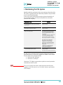
Printing History
Edition 1
Edition 2
Edition 3
Edition 4
Edition 5
Edition 6
January 1999
April 2003
August 2005
October 2009
March 2010
June 2010
Software Version 2.0
Software Version 2.0
Software Version 2.0
Software Version 2.5 to 4.1.X
Software Version 2.5 to 4.1.X
Software Version 2.5 to 4.1.X
Original Instructions
CTC Analytics AG reserves the right to make improvements and/or changes to
the product described at any time without notice.
CTC Analytics AG makes no warranty of any kind with regard to this product,
including but not limited to implied warranties of merchantability and
suitability for a particular purpose.
In no case shall CTC Analytics AG be liable for any coincidental or
consequential damage in connection with or arising from the use of this
document.
© 2009 CTC Analytics AG. All rights reserved. Neither this publication nor any
part hereof may be copied, photocopied, reproduced, translated or reduced
to electronic medium or machine readable form without the prior written
permission of CTC Analytics AG, except as allowed under copyright laws.
CTC Analytics AG acknowledges all trade names and trademarks used as the
property of their respective owners.
1
COMBI PAL / LHX PAL
PAL COMBI-xt / PAL LHX -xt
User Manual
Installation and Operation
A. Safety Information
General Considerations
The PAL System User Manual and the corresponding “Addendum” for a
specific module must be consulted by the user under all circumstances
before a unit is put in use.
Changes or modifications to this unit not expressly approved by the party
responsible for compliance could void the user’s authority to operate the
equipment.
The user shall be made aware that, if the equipment is used in a manner not
specified by the manufacturer, the protection provided by the equipment may
be impaired.
When using the PAL System, follow the generally accepted procedures for
quality control and methods development.
When using the PAL System in the field of chromatographic analysis, if a
change in the retention of a particular compound, in the resolution between
two compounds, or in peak shape is observed, immediately determine the
reason for the changes. Do not rely on the separation results until you
determine the cause of a change.
Electrical Hazards
Every analytical instrument has specific hazards, so be sure to read and
comply with the following precautions. They will help ensure the safe,
long-term use of your PAL System.
The installation category (over-voltage category) for this instrument is Level II.
The Level II category pertains to equipment that receives its electrical power
from the local level, such as an electrical wall outlet.
Use only fuses of the type and current rating specified. Do not use repaired
fuses and do not short-circuit the fuse holder.
The supplied power cord must be inserted into a power outlet with a
protective earth contact (ground). When using an extension cord, make
sure that the cord also has an earth contact.
2
COMBI PAL / LHX PAL
PAL COMBI-xt / PAL LHX -xt
User Manual
Installation and Operation
Do not change the external or internal grounding connections. Tampering
with or disconnecting these connections could endanger you and/or damage
the PAL System.
The instrument is properly grounded in accordance with these regulations
when shipped. You do not need to make any changes to the electrical
connections or the instrument's chassis to ensure safe operation.
The combination of a PAL System with a LC/MS System does require the
safety measure as described by the LC/MS System manufacturer. Detailed
instructions for the safety grounding on the LC/MS system are outlined in
the corresponding operating/installation manual.
CTC Analytics recommends using a grounding cable connected on one side
at the Injection Valve, Loop or any other suitable direct metallic contact, and
on the other side at an appropriate ground point on the LC/MS System. This
supplementary grounding measure will support the safety strategy of the
LC/MS System manufacturer.
Do not turn the instrument on if you suspect that it has incurred any kind
of electrical damage. Instead disconnect the power cord and contact a CTC
Analytics representative for a product evaluation. Do not attempt to use the
instrument until it has been evaluated. Electrical damage may have occurred
if the PAL System shows visible signs of damage, exposure to any liquids or
has been transported under severe stress.
Damage can also result if the instrument is stored for prolonged periods
under unfavorable conditions (e.g. subjected to heat, water, etc.).
Ensure that the power supply/controller unit is always placed on a dry and
clean position. Avoid any spill of liquids.
Always disconnect the power cord(s) from the power supply or from the
various power supplies if optional devices are installed before attempting
any type of maintenance.
Capacitors inside the instrument may still be charged even if the instrument
is turned off.
To avoid damaging electrical parts, do not disconnect an electrical assembly
while power is applied to the PAL system. Once the power is turned off, wait
approximately 30 seconds before you disconnect an assembly.
3
COMBI PAL / LHX PAL
PAL COMBI-xt / PAL LHX -xt
User Manual
Installation and Operation
The instrument includes a number of integrated circuits. These circuits may
be damaged if exposed to excessive line voltage fluctuations and/or power
surges.
Never try to repair or replace any components of the instrument that are not
described in this manual without the assistance of a CTC Analytics
representative.
There are no operator-serviceable or replaceable parts inside the power
supply(ies) or in the PAL System. If a power supply is not functioning, contact
a CTC Analytics representative.
The power supplies for the PAL Instrument, the Stack Cooler DW, Stack
Cooler MT and Tray Cooler have the symbols I/0 on the label for the power
switch to switch ON/OFF.
Any additional power supply for other devices, such as a Valve Module,
exhibits the symbols as shown below on the label for the power switch:
Power ON
Power OFF
The symbols warn the user that in an emergency more than one power
supply must be turned OFF or more than one power cord must be pulled
from the power supply or from the wall outlet to shut down the complete PAL
System.
If the basic PAL System is installed, then a single power supply only is
installed. Turning OFF the power supply or pulling this single power cord
will stop the complete PAL System in an emergency.
If a Stack Cooler DW, Stack Cooler MT or a Tray Cooler is installed in
combination with a PAL System, then a second power supply is installed
in the complete system. Turning OFF the power supplies or pulling the
two power cords in an emergency will stop the complete PAL System.
It is important that the power supply (ies) be in a location where the power
ON and OFF switch is accessible and easy to operate, and where it is possible
to unplug the AC power cord from the power supply/wall outlet in case of
emergency.
4
COMBI PAL / LHX PAL
PAL COMBI-xt / PAL LHX -xt
User Manual
Installation and Operation
Other Hazards
To avoid injury during PAL System operation, keep your hands away from
the syringe.
Do not operate the PAL System without the safety shield. The safety shield
must be installed for safe operation.
To avoid injury, observe safe laboratory practice when handling solvents,
changing tubing, or operating the PAL System. Know the physical and
chemical properties of the solvents you use. See the Material Safety Data
Sheets from the manufacturer of the solvents being used.
Use caution when working with any polymer tubing under pressure:
• Always wear eye protection when near pressurized polymer tubing.
• Do not use polymer tubing that has been severely stressed or kinked.
• Do not use polymer tubing, in particular no PEEK or Tefzel tubing when
using tetrahydrofuran (THF), dimethylsulfoxid (DMSO), chlorinated
organic solvents, concentrated mineral acids, such as nitric, phosphoric
or sulfuric acids, or any compounds related to the above.
Do not use vials without a sealing cap, microtiter or deepwell plates without
a plate seal. Vapor phase from organic solvents can be hazardous and
flammable. Acidic vapor phase can cause corrosion to critical mechanical
parts.
Disposal
Do not dispose of this equipment or parts thereof unsorted in municipal
waste. Follow local municipal waste ordinances for proper disposal provisions
to reduce the environmental impact of waste electrical and electronic
equipment (WEEE).
European Union customers: Call your local customer service representative
responsible for the PAL System for complimentary equipment pick-up and
recycling.
5
COMBI PAL / LHX PAL
PAL COMBI-xt / PAL LHX -xt
User Manual
Installation and Operation
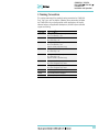
Commonly Used Symbols
Caution or refer to User Manual
Caution, Risk of Needle-Stick Puncture
Caution, Hot Surface or High Temperature
Direct Current
Alternating Current
Protective Conductor Terminal, Ground
Fuse
I
°
Electrical Power ON
Used with Main PAL Power Supply
Electrical Power OFF
Used with Main PAL Power Supply
Electrical Power ON for Only Part of the System.
Used with Optional Device(s)
Electrical Power OFF for Only Part of the System Used with
Optional Device(s)
Caution, Risk of Electrical shock (high voltage)
Disposal, Do not dispose in municipal waste.
Follow local waste regulations to reduce electrical and
electronic waste (WEEE).
6
COMBI PAL / LHX PAL
PAL COMBI-xt / PAL LHX -xt
User Manual
Installation and Operation
B. Table of Contents
A. Safety Information
2
B. Table of Contents
7
C. List of Figures
10
D. How to Use this Manual
12
E. COMBI PAL Operating Instructions
13
1. Using the Control Terminal
13
1.1. Menu Screens
13
1.2. Function Keys
14
1.3. ESCape and STOP Keys
14
1.4. Scroll Knob and ENTER Button
14
2. Methods
15
2.1. Creating Methods
15
2.2. Edit / View Methods
16
2.3. Delete Methods
16
3. Job and Job Queue
17
3.1. Building and Starting a Job Queue
17
3.2. Aborting a Job Queue
18
3.3. Restarting an aborted Job Queue
19
4. Utility Functions
19
4.1. Syringe
20
4.2. Tray
21
4.3. Injector
22
4.4. Wash Station
22
4.5. Vial
23
4.6. Dilutors
23
4.7. Tools
24
5. Logfile
24
6. Info Functions
25
6.1. Hardware
25
6.2. Software
25
6.3. Maintenance
26
6.4. Free Objects / Free Items
26
7. Setup Functions
26
7.1. Sounds
27
7.2. Time
27
7.3. Objects
27
7
COMBI PAL / LHX PAL
PAL COMBI-xt / PAL LHX -xt
User Manual
Installation and Operation
Table of Contents (contd.)
F. COMBI PAL Description and Installation
1. General System Overview
28
28
1.1. Specifications
29
1.3. Electrical Specifications
30
1.4. Physical Specifications
31
1.5. Operating and Environmental Requirements
31
1.6. Sound Pressure Level
31
1.7. Hardware and Software Requirements
32
1.8. Regulatory Compliance Requirements
32
2. Product Warranty
2.1. Statement of Limited Product Warranty
3. Installation
33
33
35
3.1. Unpacking the Components
35
3.2 Assembling the COMBI PAL
35
3.3. Electrical Connections
42
4. COMBI PAL Object Positions
43
4.1. Defining Object Positions
43
4.2. Description of Object Positions
46
5. Syringes
54
5.1. Selecting Syringes
54
5.2. Syringe Priming (for Liquid Syringe Types only)
54
5.3 Installing a Syringe for Liquid Injections
54
5.4. Removing a Syringe for Liquid Injections
56
5.5. Installing a Syringe for Headspace Injections
56
5.6. Removing a Syringe for Headspace Injections
57
6. Interfacing the COMBI PAL to Other Devices
6.1. Synchronization and Output Signals
7. PAL System Software
58
58
60
7.1. PAL Loader Software
60
7.2. PAL Object Manager Software
61
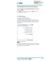
8. Establishing Communication with Computer
62
8.1 COM Port Settings
62
8.2 Setting up LAN Communication
63
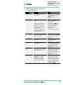
8.3 Troubleshooting for Serial or LAN Communication
66
8
COMBI PAL / LHX PAL
PAL COMBI-xt / PAL LHX -xt
User Manual
Installation and Operation
Table of Contents (contd.)
9. Special Functions
67
9.1. How to Access “Extended User Mode”
67
9.2. Section “F3-Setup”
68
9.3. Section “F3-Setup” / Objects
72
G. Troubleshooting PAL and PAL-xt System
80
H. Replacing Parts
82
1. MOTIO Board
82
2. CPU Board
84
3. Control-xt Board
85
4. Agitator
86
5. Injection Unit
86
6. Wash Station
86
I. Maintaining the PAL System
87
J. Appendices
88
1. Definition of Terms
88
2. Naming Convention
91
3. COMBI PAL and –xt Injection Cycles
92
3.1. COMBI PAL "GC-Inj" Cycle
92
3.2. GC PAL "GC-InjS" Cycle
94
3.3. COMBI PAL "HS-Inj" Cycle
96
3.4. COMBI PAL "GC-Dual" Cycle
98
4. PAL Firmware Overview
100
4.1. COMBI PAL Flow Chart based on PAL Firmware Version 2.5.X.
100
4.2. PAL COMBI-xt PAL System Flow Chart based on
PAL Firmware Version 4.1.X
104
5. External Connectors for PAL and -xt System
108
6. Intended Use for PAL System
112
6.1. Introduction
112
6.2. Intended Use
112
6.3. Disclaimer and Restrictions on Use
112
7. PAL Accessories
113
9
COMBI PAL / LHX PAL
PAL COMBI-xt / PAL LHX -xt
User Manual
Installation and Operation
C. List of Figures
Figure 1
Figure 2
Figure 3
Figure 4
Figure 5
Figure 6
Figure 7
Figure 8
Figure 9
Figure 10
Figure 11
Figure 12
Figure 13
Figure 14
Figure 15
Figure 16
Figure 17
Figure 18
Figure 19
Figure 20
Figure 21
Figure 22
Figure 23
Figure 24
Figure 25
Figure 26
Figure 27
Figure 28
Figure 29
Figure 30
Figure 31
Figure 32
Figure 33
Figure 34
Figure 35
Figure 36
Figure 37
Figure 38
Figure 39
Figure 40
Figure 41
Figure 42
Figure 43
Figure 44
Figure 45
PAL Control Terminal and Conventions
Accessing a Method Screen
Verifying Tray with corresponding Tray Type
Example of Job Queue Screen
Selecting Utilities Functions
Selecting Info Functions
Selecting Setup Functions
COMBI PAL Major System Components
Attachment of Mounting Claws
Attaching the PAL Injection Unit
Connecting the Injection Unit Ribbon Cable
Inserting the Injection Unit Mounting Torx Screws
COMBI PAL with Injection Unit and Standalone Supports
Installing the Keypad Terminal
Installing the Flush Gas Regulator
Installing the Wash Station
Installing the Agitator
Installing a Tray Holder
Electrical Connections for Combi PAL System
Electrical Connections for PAL COMBI-xt System
Object Reference Position
Menu Screen Object Tray Holder
Inclined Tray, Corrections for X-,Y-,Z-Axes
Tray Holder Reference Position
Demonstrating a possible Inclination of Tray in X-,Y-,Z-Axes.
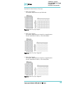
Tray Type VT 32
Tray Type DW96
Utilities Function “Trays”
Adjusting “Offset X,Y, Z” for Tray Position 001
Adjusting Row Inclination at Second Tray Corner Position
Adjusting Column Inclination at Third Tray Corner Position
Wash Station Wash1/Wash2 Reference Point
Wash Station Waste/Waste2 Reference Position
Wash Station Standard Reference Position
GC Injectors (e.g. GC Inj1) Reference Position
Agitator Reference Position
Syringe and Syringe Adapter for Liquid Injections
Installing and Removing a Syringe for Liquid Injections
Headspace Syringe and heated Syringe Adapter
Installing and Removing a Headspace Syringe
Removing a Headspace Syringe from the
Heated Syringe Adapter
COM Port Settings
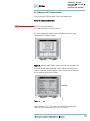
Reading MAC Address from Ethernet Communication Port
PAL-xt Communication Settings
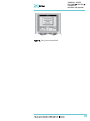
Setting Communication Mode
10
COMBI PAL / LHX PAL
PAL COMBI-xt / PAL LHX -xt
User Manual
Installation and Operation
List of Figures (contd.)
Figure 46
Figure 47
Figure 48
Figure 49
Figure 50
Figure 51
Figure 52
Figure 53
Figure 54
Figure 55
Figure 56
Figure 57
Figure 58
Figure 59
Figure 60
Figure 61
Selecting “Setup” in Extended User Mode
Selecting “Objects” in Extended User Mode
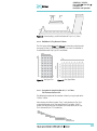
Pattern Tray Type “Regular”
Pattern Tray Type “Staggered+”
Pattern Tray Type “Staggered-“
Replacing MOTIO Board
Replacing CPU Board
Replacing Control-xt Board
COMBI PAL Firmware Overview, Page 1
COMBI PAL Firmware Overview, Page 2
COMBI PAL Firmware Overview, Page 3
COMBI PAL Firmware Overview, Page 4
PAL COMBI-xt Firmware Overview, Page 1
PAL COMBI-xt Firmware Overview, Page 2
PAL COMBI-xt Firmware Overview, Page 3
PAL COMBI-xt Firmware Overview, Page 4
11
COMBI PAL / LHX PAL
PAL COMBI-xt / PAL LHX -xt
User Manual
Installation and Operation
D. How to Use this Manual
note
This User Manual covers the COMBI PAL and PAL COMBI-xt Systems. Issues
specific to the PAL COMBI-xt model have been emphasized as such.
Follow the description given in this manual to Install and operate the PAL
model “LHX PAL,” which differs only by its X-axis length of 120 cm as
compared to 80 cm for the COMBI PAL model and thus is not handled
separately. Thus, model PAL LHX-xt is also not handled separately.
Unless stated otherwise, this manual refers to all COMBI PAL models.
The manual is divided into following major sections:
•
•
•
•
•
•
•
•
•
Safety Information
COMBI PAL Operating Instructions
Specifications
Product Warranty
COMBI PAL Description and Installation
Troubleshooting
Replacing Parts
Maintaining PAL System
Appendices
The "COMBI PAL Operating Instructions" in section E are intended for
infrequent PAL users or new users who already have experience using
automated systems to perform standard analytical methods.
note
The COMBI PAL must be installed and set up properly before the Operating
Instructions in Section E can be used.
Users who are installing a COMBI PAL system or COMBI PAL accessories, or
who need to adjust an installed system, should consult "COMBI PAL
Description and Installation" in Section F.
The Appendices provide useful information such as the Software Flow Chart,
Definition of Terms, Injection Cycle parameter descriptions, or the COMBI PAL
accessories guide.
12
COMBI PAL / LHX PAL
PAL COMBI-xt / PAL LHX -xt
User Manual
Installation and Operation
E. COMBI PAL Operating Instructions
1. Using the Control Terminal
The following procedures present the key steps required to set up and
process multiple groups of samples with the COMBI PAL. They are intended
to provide an overview for new users and a reminder for infrequent users.
The COMBI PAL and all accessories should be installed with Objects defined
correctly. A syringe of the specific type called for by a particular method
should also be installed.
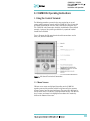
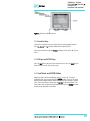
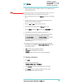
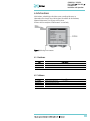
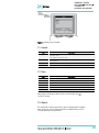
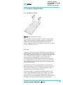
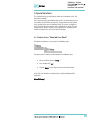
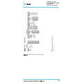
Figure 1 illustrates the PAL control terminal and the conventions used to
enter, edit, and view information.
Figure 1. PAL Control Terminal and Conventions
1.1. Menu Screens
Different menu screens are displayed, depending on the COMBI PAL
operating state and the particular function being accessed by the operator.
All menu screens have the same basic format. The menu title is displayed at
the top of the screen. A list of items is displayed below the title. The date and
time, or status, are shown in the highlighted area above the Function key
labels on the bottom of the screen.
13
COMBI PAL / LHX PAL
PAL COMBI-xt / PAL LHX -xt
User Manual
Installation and Operation
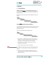
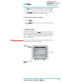
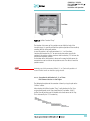
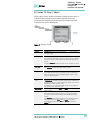
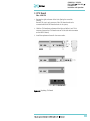
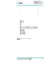
Figure 2. Accessing a Method Screen
1.2. Function Keys
Options for a particular menu are assigned to the corresponding function
keys (F1, F2, F3 and F4) directly below each function key label.
Pressing the function key labeled Home will always return to the Job Queue
menu.
1.3. ESCape and STOP Keys
Press the ESCape key to return to the previous menu. Press the STOP key to
abort the current Cycle, Job, or Job Queue.
1.4. Scroll Knob and ENTER Button
Rotate the outer knob to scroll through items in a menu list. To select a
highlighted item press the central knob (ENTER button). Then use the outer
knob to scroll through available options for that item or to change a numeric
value. Then press the inner knob again to ENTER the displayed option. The
inner knob is also used for other operations that require an ENTER operation
to continue or complete an operation.
14
COMBI PAL / LHX PAL
PAL COMBI-xt / PAL LHX -xt
User Manual
Installation and Operation
2. Methods
2.1. Creating Methods
Methods can be defined by the user and assigned names up to eight
characters in length. Methods can be created, copied, edited, and viewed
from the Methods menu. Methods can be viewed (but not edited) from the
Job Queue menus.
Methods are created by either copying an existing Method or creating a new
Method.
To copy a Method, complete the sequence as follows.
You will be prompted to enter a name for the new Method.
Use the scroll knob and the left-right arrow function keys (F2 and F3) to select
among alphanumeric characters and spaces. Press the ENTER function key
(F4) to accept the name.
To create a new Method, complete the following steps:
1. Assign and enter a new Method name as above. After a copy of the
Method has been created, the Method parameters will display and can
be edited. The Cycle and Syringe entries cannot be changed;
2. If the Method is new (i.e. added), select and enter a Cycle that is
appropriate for the application;
3. Select the specific Syringe to be used by the Method;
note
Once a Method has been created and saved, the Cycle and Syringe cannot
be changed. To use a different Cycle or Syringe, a new Method must be
created.
4. Assign Parameter values according to the application requirements.
Consult Appendix point 3, COMBI PAL "Injection Cycle Parameters" for
details on specific items;
15
COMBI PAL / LHX PAL
PAL COMBI-xt / PAL LHX -xt
User Manual
Installation and Operation
2.2. Edit / View Methods
Method parameters (excluding Cycle and Syringe) can be viewed and
changed from the Method menu as follows:
Complete the following menu selections:
1. Scroll to and select the parameter to be changed. Assign the new value
and press the ENTER key;
2. Exit from Parameter List by pressing either the Home function key (F4)
to return to the top-level Job Queue menu or the ESCape key to return
to the previous menu;
3. Method contents may be viewed from the Job Queue displays by
selecting the desired Job, pressing ENTER and the View Method function
key.
2.3. Delete Methods
Methods can be deleted from the Methods menu. Methods in use by an
active Job cannot be deleted. Complete the following menu selections to
delete a Method.
16
COMBI PAL / LHX PAL
PAL COMBI-xt / PAL LHX -xt
User Manual
Installation and Operation
3. Job and Job Queue
A Job bundles the specified Tray with the designated vials (samples) and with
the Method to run those samples. Another term often used for “Job” in the
chromatographic field is “sequence”.
If more than one Job is prepared, the term Job Queue is used.
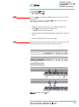
Before a Job can be activated the operator must verify that the Tray Type
matches the specified Tray and vial size (type). This step is done in Utilities
class.
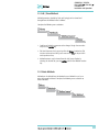
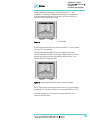
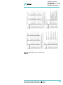
Figure 3. Verifying Tray with corresponding Tray Type
Select the corresponding Tray Type. By activating function key “F3” the
injection unit can be moved to the first position and to another two corner
positions to verify the correct selection of the Tray Type and teaching position.
3.1. Building and Starting a Job Queue
1. Power up the COMBI PAL. The JOB QUEUE screen is displayed;
Figure 4. Example of Job Queue Screen
17
COMBI PAL / LHX PAL
PAL COMBI-xt / PAL LHX -xt
User Manual
Installation and Operation
2. Load a sample Tray onto an available location in a Tray Holder. Note the
corresponding Tray name;
note
If a sample Tray contains 10 mL sample vials and the "HS-Inj" cycle is used,
insert the supplied adapters into the Agitator sample positions.
3. Add a new Job for the Tray. Press the Add Job key to bring up the default
Job;
4. For TRAY, select the Tray name (e.g. Tray1) that corresponds to the
location of the Tray that was just loaded;
5. Enter the First and Last sample number for this Job;
6. Select and enter the sample processing Method for this Job;
7. Press the Home function key (F4) to return to the JOB QUEUE screen;
8. To add additional samples to be processed, repeat steps 2 – 7;
9. If necessary, replace and/or clean the syringe (liquid versions only).
Press the Menu key to see the available options for changing
(F1 Change Syringe) and cleaning F2 Clean Syringe). To completely
remove air bubbles, the syringe should be primed manually;
(See Section F. “Description and Installation”, point 5.2,
"Syringe Priming".)
10. If only one Job is to be processed, select the Job with the scroll knob.
Press Start key. In the dialog box "Select Job(s) to Process" select one
of the following options:
•
•
•
All (Entire Job Queue starting from the top)
Selected (Job selected with the cursor bars)
Resume (Continue with the next Job after the one aborted.)
3.2. Aborting a Job Queue
1. Press STOP;
2. Select one of the available options
(Continue, Sample, Job, or Job Queue);
3. Select Continue to resume processing with the current sample;
4. Select Sample if there is a problem with only the current sample.
Processing will resume with the next sample;
18
COMBI PAL / LHX PAL
PAL COMBI-xt / PAL LHX -xt
User Manual
Installation and Operation
5. Select Job to abort processing all samples in the current Job. Processing
will resume with the next Job. The aborted Job is marked with an X;
6. Select Job Queue to abort processing of all Jobs. The JOB QUEUE screen
will be displayed. The aborted Job is marked with an X.
3.3. Restarting an aborted Job Queue
1. Press the START key;
2. Select the Resume option. The job after the last one marked as aborted
will be started.
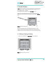
4. Utility Functions
Utility functions, selectable from the Menu screen, provide quick access to
checking operations and parameters that may need to be changed. These
functions are available for the actual Syringe, Trays, Injectors, and the Wash
Station. They allow access to key functions without having to set up and
execute a Method and Job.
note
If an item is used in the sample processing cycle, the appropriate Utility
value will be overwritten by the Method value.
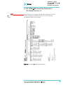
Figure 5. Selecting Utilities Functions
19
COMBI PAL / LHX PAL
PAL COMBI-xt / PAL LHX -xt
User Manual
Installation and Operation
4.1. Syringe
The following functions are available by pressing a Function Key:
Function Key
F1 Chang Syr
Description
The syringe is moved to a position in which the syringe assembly can be completely lowered to
facilitate removal of the syringe adapter. The syringe can then be removed from the adapter and
replaced. A prompt will be displayed to specify the new syringe. The syringe must be installed
before pressing Enter. (See Section F. “Description and Installation”, point 5 "Syringes".)
F2 Clean Syr
This Function is used to clean or prime the syringe prior to use. After selecting F2 either Wash1
or Wash2 can be selected.
F3 Set Pos
F4 HOME
Set Pos is used to define the Chang Syr position.
The Injection Unit moves to its HOME position and the Job Queue Menu is displayed.
The following Syringe items may be changed by selecting the particular item:
Item
Description
Actual ID
Indicates the identification number (ID) of the currently inserted syringe. If the syringe detection
system is set to manual, the message “Syringe: No syringe" is displayed.
Fill Volume
This parameter serves to control the filling of the syringe. It can occur that air bubbles remain below
the plunger after the first pull up. If the plunger is moved up and down several times (see Fill
Strokes), these air bubbles are worked out. With this operation the syringe can be completely filled
even when using very small sample volumes.
Fill Strokes
Number of fill strokes. All fill strokes, except the last one, use the selected fill volume. If the
selected sample volume is higher than the fill volume, the sample volume is used for all fill
strokes. If zero is selected the plunger is pulled up only once using the sample volume value.
Pullup Del
By using this item a delay time can be selected between sample pullup and ejection while filling the
syringe. When the plunger reaches the zero position during the fill strokes, the system waits half the
Pullup Del time. This allows for an air bubble to float away from the needle tip. This feature is especially
useful for removing any air bubble in the syringe and handling viscous fluids.
Fill Speed
Speed of plunger movement used in all syringe filling operations.
Eject Speed
Speed of plunger movement used in all syringe eject operations except sample injection.
Inject Speed
Speed of plunger movement for sample injection. Typically used for “Fill Strokes”.
Standby Temp*
Sets the temperature for a heated syringe during standby mode,
(e.g. before or after a Job/Job Queue is processed).
Actual Temp *
Indicates the actual (current) syringe temperature
Plunger Chnge Pos
Plunger position during Chang Syr operation. The syringe plunger is moved to a position where
the syringe can be removed and replaced. The value may be changed for different types of
syringes.
* Available for Agitator only
20
COMBI PAL / LHX PAL
PAL COMBI-xt / PAL LHX -xt
User Manual
Installation and Operation
4.2. Tray
After selecting the particular Tray to be accessed, the following functions are
available:
Function Key
F1 Start Agi *
Description
F1 starts the spinning motion of the agitator. It may be used to test the agitator function or to
optimize the spinning speed for particular applications.
F2 Block NdlG
F2 activates Needle Guide blocking. The option after activation is “Rel NdlG”, releasing Needle
Guide Blocking. It may be used to test the functionality of the solenoid that blocks the needle
guide.
F3 Movto nnn
This function serves as a quick check to determine if the X,Y,Z coordinates are defined correctly
for the selected Tray. To use this utility the selected Tray, including the sample vials, must be
present. After pressing "Movto 001" the Injection Unit moves to sample position no.1. This
procedure can be repeated for the last sample position in the first row and the last sample
position.
F4 HOME
The Injection Unit moves to its HOME position and the Job Queue Menu is displayed.
*Available for Agitator only.
The following Tray items may be changed by selecting the particular item:
Item
Description
Needle Penetr
Needle penetration depth into the sample vial. The needle penetration depth for the selected Tray
may be changed by entering the desired value.
Tray Type
The Tray Type which is selected for the Tray is shown. If the Tray enables the use of different
Tray Types it can be changed at this position.
Tray Offset X
If necessary, a correction to the ideal X-position of “Position 1” can be made by using
“Tray Offset X”.
Tray Offset Y
If necessary, a correction to the ideal Y-position of “Position 1” can be made by using
“Tray Offset Y”.
Tray Offset Z
If necessary, a correction to the ideal Z-position of “Position 1” can be made by using
“Tray Offset Z”.
dxRow
Correction of any inclination of a Tray (plate) in the X-axis of a row (see Fig. 25 for details).
dyRow
Correction of any inclination of a Tray (plate) in the Y-axis of a row (see Fig. 25 for details).
dzRow
Correction of any inclination of a Tray (plate) in the Z-axis of a row (see Fig. 25 for details).
dxCol
Correction of any inclination of a Tray (plate) in the X-axis of a column (see Fig. 25 for details).
dyCol
Correction of any inclination of a Tray (plate) in the Y-axis of a column (see Fig. 25 for details).
dzCol
Correction of any inclination of a Tray (plate) in the Z-axis of a column (see Fig. 25 for details).
Standby Temp*
Sets the temperature for the Agitator during standby mode,
(e.g. before or after a Job/Job Queue is processed).
Actual Temp *
Indicates the actual agitator temperature.
Speed *
Sets the Agitator spinning speed. Usually it has to be set as high as possible, but not so high that
the liquid does not move up to the septum. Check the correct speed by inserting a spacer below
the vial inside the agitator so the liquid level is visible. Try different speeds and monitor the liquid
level.
Agi On Time *
Sets how long the Agitator spins in one direction.
Agi Off Time *
Sets how long the Agitator stops before it reverses the direction of spin. If this value is set to 0,
only the clockwise direction with no interrupts will be used.
*Available for Agitator only
Items displayed in “italic” are available beginning with PAL Firmware Version 4.1.X.
note
A “staggered pattern” is selectable in firmware class “Tray Type”. For details see section F. “Description
and Installation”, point 9.3.1 “Tray Type”.
21
COMBI PAL / LHX PAL
PAL COMBI-xt / PAL LHX -xt
User Manual
Installation and Operation
4.3. Injector
After selecting the particular Injector to be accessed, the following Functions
are available:
Function Key
F3 Movto Inj
F4 HOME
Description
The Injection Unit moves to the selected injector position. With this function, e.g. the injectors
GC-Inj1, Waste, Waste2 and Flush can be accessed. By selecting the parameter "Needle Penetr"
on the same screen, the Injector Needle Penetration value can be checked or changed.
The Injection Unit moves to its HOME position and the Job Queue Menu is displayed.
The following Injector item may be changed by selecting the particular item:
Item
Needle Penetr
Description
By selecting the parameter "Needle Penetr" the Injector Needle Penetration value can be checked
and/or changed. To ensure reproducible sample injections and minimize carryover it is critical
that the needle penetration depth be accurately set.
4.4. Wash Station
After selecting the specific Wash Station, the following functions are available:
Function Key
F3 Movto Wash
F4 HOME
Item
Description
The injection unit moves to the selected Wash Station port. By selecting the Parameter "Needle
Penetr" on the same screen the Wash Station Needle Penetration value can be checked or
changed.
The injection unit moves to its HOME position and the Job Queue Menu is displayed.
Description
Needle Penetr
By selecting the Parameter "Needle Penetr" the Wash Station Needle Penetration value can be
checked and/or changed.
Rinse Time
If rinse time is activated (value > 0), the solenoid of a Fast or Active Washstation opens for the
specified time after the syringe needle has been removed from the wash port (after completion
of the syringe wash cycle).
The solvent flows into the wash port without the restriction of the needle; be aware of higher
solvent consumption.
The following Wash Station items may be changed by selecting the particular
item:
Item
Description
Needle Penetr
By selecting the parameter "Needle Penetr" the Wash Station needle penetration value can be
checked and/or changed.
Rinse Time
If rinse time is activated (value > 0), the solenoid of a Fast or Active Washstation opens for the
specified time after the syringe needle has been removed from the wash port (after completion
of the syringe wash cycle).
The solvent flows into the wash port without the restriction of the needle; be aware of higher
solvent consumption.
22
COMBI PAL / LHX PAL
PAL COMBI-xt / PAL LHX -xt
User Manual
Installation and Operation
4.5. Vial
After selecting the specific Vial type*, the following functions are available:
Function Key
F3 Movto Vial
F4 HOME
Description
The injection unit moves to the selected vial type. By selecting the parameter "Needle Penetr"
on the same screen, the Wash Station Needle Penetration value can be checked or changed.
The Injection Unit moves to its HOME position and the Job Queue Menu is displayed.
* Available Vial types:
- Standard: Vial in Standard Washstation for GC (front position).
- Fiber Exp: Position to block needle guide.
Mainly used for SPME application. See SPME User Manual.
Item
Needle Penetr
Description
By selecting the parameter "Needle Penetr" the wash station needle penetration value can be
checked and/or changed.
4.6. Dilutors
After selecting the specific Dilutor, the following functions are available:
Function Key
F1 Prime
F2 Chang DSyr
Description
The Dilutor syringe is primed with solvent after activating the F1 function.
F4 HOME
The Injection Unit moves to its HOME position and the Job Queue Menu is displayed.
Activating F2 moves the plunger of the Dilutor Syringe to standby position to allow easy access
to change the syringe.
The following Dilutor items can be changed by selecting the particular item:
Item
Syringe
Syr Dilut Pos
Dilutor Syr
Prime Volume
Pullup Delay
Fill Speed
Eject Speed
Eject Delay
Description
Indicates the Dilutor side-port syringe inserted in the Z-axis. This function allows
selecting another syringe size.
Activating this function moves the plunger of the side port syringe up by the specified
distance. This allows adjustment of the plunger tip of the side port syringe exactly
above the lower side port (solvent inlet). This fine tuning is necessary after changing a
side port syringe to allow unrestricted solvent flow.
Indicates Dilutor Syringe is installed. If the syringe size is changed, this item must be
adapted accordingly. The syringe-specific dimensions are coordinated by this function.
A volume to prime the Dilutor Syringe can be specified. The allowed range can be
fourfold higher than the actual syringe volume. This allows filling and emptying a
dilutor syringe more often than just once.
Using this item permits selecting a delay time between solvent filling and ejection
while filling (or priming) the syringe.
Speed of plunger movement of Dilutor Syringe used in all syringe filling operations.
Speed of Dilutor Syringe plunger movement used in all dilutor syringe eject
operations.
Using this item permits selecting a delay time between solvent ejection and filling
while filling (or priming) the syringe.
23
COMBI PAL / LHX PAL
PAL COMBI-xt / PAL LHX -xt
User Manual
Installation and Operation
4.7. Tools
note
The Object class “Tools” is available with PAL Firmware version
3.0.X , 4.1.X. or higher.
After selecting the specific tool, the following functions become available:
Function Key
F1 Chk Offs
F4 HOME
Description
The item “Check Offset” can be used to verify the offset from the syringe needle tip to the tool tip.
This item is mainly used for the MALDI tool; it is not active for the MHE tool.
The injection unit moves to its HOME position and the Job Queue Menu is displayed.
The following tool items may be changed by selecting the particular item:
Item
Description
Teach Point
The reference point at which to teach the Object (Tool; MHETool) is selectable. In the case of
the MHETool, no extra position is necessary. The Parking Station is the fix point. Select “None.”
ToolOffset X
If necessary, a correction to the ideal X-position of the MHETool can be made by using
“ToolOffsetXX”.
ToolOffset Y
If necessary, a correction to the ideal Y-position of the MHETool can be made by using
“ToolOffsetY”
ToolOffset Z
If necessary, a correction to the ideal Z-position of the MHETool can be made by using
“ToolOffsetZ”
A “ToolOffsetZ” of -48.0 mm is necessary to position the MHETool on the sample vial.
5. Logfile
The PAL logfile cannot be read-out directly on the terminal display.
However, the function key “F3” does allow a print out. A serial printer has to
be connected to port “SER2” for the PAL System and to the port “SER1” for
PAL-xt System. If a serial printer is not available use a serial/parallel converter.
24
COMBI PAL / LHX PAL
PAL COMBI-xt / PAL LHX -xt
User Manual
Installation and Operation
6. Info Functions
Info functions, selectable from the Menu screen, provide quick access to
information to be viewed. These info functions are available for the Hardware,
Software Maintenance, Free Objects, and Free Items.
All items with the exception of “Maintenance” are read only.
Figure 6. Selecting Info Functions
6.1. Hardware
Item
Description
CPU SNo
The serial number (SNo.) of the PCB “APR CPU” is displayed-
CPU ID
Version number of the PCB “APR CPU”.
MOTIO ID
Version number of the PCB “APR CPU”.
6.2. Software
Item
Description
PAL Firmware
Firmware version of PAL System.
Head Firmware
Firmware version PAL Injection Unit.
Terminal FW
Firmware version PAL Terminal.
Altera Firmware
Firmware version of the Altera component.
25
COMBI PAL / LHX PAL
PAL COMBI-xt / PAL LHX -xt
User Manual
Installation and Operation
6.3. Maintenance
Item
note
Description
PlgStrokeCnt
This is a counter for syringe plunger movements. The actual number of strokes is displayed. If the
counter reaches the set limit (PlgStrkeLim), a warning is displayed at the next start of a job (run).
The system continues but signals the user to verify syringe conditions. The counter can be set
back to zero to restart.
There is only one counter for a syringe. If syringe types are changed the system continues to
count as if it were the same type.
PlgStrokeLim
An upper limit for the syringe plunger strokes can be set.
Inject Count
This counter monitors the number of injections. The number of penetrations into the GC injector
is a helpful tool for the user to decide on a replacement of the injector system. The actual number
of injections is displayed. If the counter reaches the set limit (PlgStrokeLim), a warning is
displayed at the next start of a job (run) (Inject Limit). The same counter is used for valve
switches (HPLC technique).
Inject Limit
An upper limit for the number of injections can be set.
Counters for the plunger movement and injector penetrations are
available with PAL Firmware version 2.5.X or higher.
6.4. Free Objects / Free Items
In addition to the core software, the PAL Firmware contains data for the
“Firmware Objects”. There are different classes of Objects, such as Syringes,
Trays, Tray Holders, etc. Each class of Objects contains “Items”. The items
contain the actual data such as X-, Y-, Z-positions.
The data are stored in a flash memory backed up by a battery.
To optimize RAM and Flash memory use, a certain section of memory has
been reserved by the software for each of the Objects and Object Items.
The percentage shown in the “Info” section provides an indication as to how
much of the reserved software space is still available.
7. Setup Functions
The Setup functions, selectable from the Menu screen, allow accessing
various functions for the PAL System. The “Sound”, “Time” and “Objects” are
basic functions used at installation or if changes have been made over time.
26
COMBI PAL / LHX PAL
PAL COMBI-xt / PAL LHX -xt
User Manual
Installation and Operation
Figure 7. Selecting Setup Functions
7.1. Sounds
Item
Description
Message Box
A specific dual beep tone signals that a pop-up window (Message Box) for user intervention
appears on the screen.
This beep signal can be turned on or off.
Warn Move
A beep sound is heard at the start of the PAL movement. It is advisable to keep this function turned
on for safety reasons.
End Cycle
A beep sound is heard at the end of a cycle. Select as desired.
End Job
A beep sound is heard at the end of a cycle. Select as desired.
7.2. Time
Item
Description
Year
The “year” can be set for the PAL internal clock
Month
The “month” can be set for the PAL internal clock.
Day of Month
The “day” can be set for the PAL internal clock.
Hours
The “hours” can be set for the PAL internal clock.
Minutes
The “minutes” can be set for the PAL internal clock.
Seconds
The “seconds” can be set for the PAL internal clock.
After setting or resetting the date and time, use the function key “F1”
“Set Time” to store.
7.3. Objects
The various PAL Firmware Object classes can be selected and the functions
most used by the user are directly accessible. For detailed listing see PAL
Firmware overview in the appendices.
27
COMBI PAL / LHX PAL
PAL COMBI-xt / PAL LHX -xt
User Manual
Installation and Operation
F. COMBI PAL Description and Installation
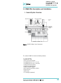
1. General System Overview
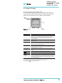
Figure 8. COMBI PAL Major System Components
The standard COMBI PAL includes the following hardware:
1 X-, Y-axes assembly
1 Injection Unit, Z-axis
1 Flush Gas Pressure Regulator
1 Tray Holder/Tray for 1 mL / 2 mL vials
1 Tray Holder/Tray for 10 mL / 20 mL vials
1 Syringe kit for liquid injections
1 Syringe kit for heated Syringes
1 Heated, six-position Agitator
1 Wash Station for two different solvents
1 Keypad terminal
1 Safety Guard
1 GC mounting kit (optional)
28
COMBI PAL / LHX PAL
PAL COMBI-xt / PAL LHX -xt
User Manual
Installation and Operation
1.1. Specifications
1.1.1. Sample Capacity
•
•
•
98 x 2 mL vials per Tray
200 x 1 mL vials per Tray
32 x 10 mL / 20 mL vials per Tray
(up to three Trays can be configured)
•
•
•
•
108 x 2 mL vials per Stack Cooler 2 DW (2 x 54 vials)
216 x 2 mL vials per Stack 4 DW (without cooling/heating)
2 Micro- Deepwell plates per Stack Cooler 2 DW
4 Micro- Deepwell plates per Stack 4 DW
1.1.2. Thermostatted Sample Tray
•
•
Tray Cooler, optional, 4 °C – 70 °C
Stack Cooler 2 DW, optional, 4 °C – 40 °C
1.1.3. Liquid Injection Range
•
•
•
•
1 µL – 10 µL with standard 10 µL syringe
Down to 0.1 µL with sandwich technique or
Optional 1.2 µL syringe
Up to 50 – 500 µL with optional 500 µL syringe
1.1.4. Headspace Injection Range
•
•
•
250 – 2500 µL with standard 2.5 mL heated syringe
Down to 100 µL with optional 1.0 mL heated syringe
Up to 5000 µL with optional 5.0 mL heated syringe
1.1.5. Heated Syringe Temperature
•
35 °C – 150 °C selectable in 1 °C increments
1.1.6. Incubator (Agitator)
•
•
•
Six heated vial positions for 2 / 10 / 20 mL vials
Temperature range 35 °C – 200 °C, selectable in 1 °C increments
Orbital interval shaking, speed 250 – 750 rpm
29
COMBI PAL / LHX PAL
PAL COMBI-xt / PAL LHX -xt
User Manual
Installation and Operation
1.1.7. Replicate Injections
•
1 – 99 from one vial
1.1.8. Minimum Sample Volume
•
1 µL from a 3 µL sample in 1 mL tapered micro vial
in liquid injection mode
1.2. Performance Specification
The performance specifications are available as part of a specific, separate
document.
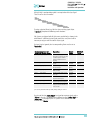
1.3. Electrical Specifications
Parameter
Requirement
a
Protection class
b
Over voltage category
c
Pollution degree
d
Moisture protection
Voltage
Current
Fuse
Class I
Category II
2
Normal (IPXO)
36 VDC
3.2 A
T6.3 A/250 V
PAL System Power Supply
Input line voltage
Input line frequency
Input power
Output voltage
Output current
Grounded AC, 100 to 240 V
50/60 Hz
4A
36 VDC
4.16 A
a: Protection Class I:
Protection class describes the insulating scheme used in the instrument to protect the
user from electrical shock. Class I identifies a single level of insulation between live
parts (wires) and exposed conductive parts (metal panels), in which the exposed
conductive parts are connected to a grounding system. In turn this grounding system
is connected to the third pin (ground pin) on the electrical power plug.
b: Over Voltage Category II:
Over Voltage category II pertains to instruments that receive their electrical power
from a local level such as an electrical wall outlet.
c: Pollution Degree 2:
This is a measure of pollution on electrical circuits that may produce a reduction of
the dielectric strength or surface resistivity.
Degree 2 refers to normally only non-conductive pollution.
Occasionally, however, a temporary conductivity caused by condensation must be
expected.
d: Moisture Protection:
Normal (IPXO) – IPXO means that there is NO Ingress Protection against any type of
dripping or sprayed water. The X is a place holder to identify protection against dust
if applicable.
30
COMBI PAL / LHX PAL
PAL COMBI-xt / PAL LHX -xt
User Manual
Installation and Operation
1.4. Physical Specifications
Parameter
COMBI PAL Systems
Requirements
Height
Depth
Width
Weight
648 mm (25.5 in)
385 mm (14.1 in.)
828 mm (32.6 in.)
10 kg (22 lbs.) without accessories
1.5. Operating and Environmental Requirements
Parameter
Requirements
Operating temperature range
Maximum relative humidity
Bench space
4 to 40 C (39 to 104 F)
75%, non-condensing
At least 16 cm (6 in.) at the rear.
Access to power switch(es) and power cord(s).
Clean, level and smooth surface.
Solid bench plate.
Negligible
Negligible
Vibration
Static electricity
o
o
1.6. Sound Pressure Level
Parameter
Requirements
Sound Pressure Level
Measured value: 62 dBA
(PAL System used for measurement)
One meter from the equipment in the direction
of maximum sound pressure level.
st
According to UL 610107A-1, 1 Edition,
clause 12.5.
Limit < 85 dBA
dBA = ”A weighted” sound pressure level
31
COMBI PAL / LHX PAL
PAL COMBI-xt / PAL LHX -xt
User Manual
Installation and Operation
1.7. Hardware and Software Requirements
1.7.1. Hardware Requirements
In order to operate a PAL System, the electronic control board must be
compatible with the corresponding PAL System.
-
PAL System operated with PAL Firmware version 2.X.X. or 3.0.X:
either the combination of ‘APR CPU’ and ‘APR MOTIO’ or the
‘APR Control’ boards can be used.
PAL-xt systems operating with PAL Firmware version 4.1.X or higher:
‘APR Control-xt ’ board must be installed.
A PAL System can be upgraded to a PAL-xt System; for details contact your
CTC Analytics representative.
For specific PAL hardware Modules, a minimum PAL Firmware version is
required. For example, a PAL Dilutor Option requires the PAL Firmware
version 2.3.X or higher, and a PAL DLW Option requires the PAL Firmware
version 4.1.X or higher. Details are given either in the corresponding
‘Addendum to PAL User Manual’ or in the ‘Addendum to PAL User Manual
for PAL Object Manager Software’.
1.7.2. Software Requirements
The various PAL Software programs, such as PAL Loader or PAL Object
Manager, are operated with Microsoft Windows Operating systems, such as
Windows XP and Vista. For details, see the corresponding ‘Addendum to the
PAL User Manual’.
The PAL System can be controlled using PAL control software, the Cycle
Composer, or any data system software that controls the PAL using the Cycle
Editor for PAL ICC interpretation (e.g. Analyst, ChemStation, Empower,
EZChrom, MassLynx, Xcalibur).
For details on software requirements for integration of the PAL System with
other data handling systems (CDS), contact your CTC Analytics representative
or the manufacturer’s representative of the other CDS software program.
1.8. Regulatory Compliance Requirements
As of the date of publication, this product is compliant with current RoHS and
WEEE regulations.
•
•
note
Directive 2002/95EC, RoHS
Directive 2002/96/EC, WEEE
CTC Analytics AG reserves the right to make improvements and/or changes
to the product specifications without notice.
32
COMBI PAL / LHX PAL
PAL COMBI-xt / PAL LHX -xt
User Manual
Installation and Operation
2. Product Warranty
2.1. Statement of Limited Product Warranty
What does this Warranty cover?
CTC Analytics AG warrants only that its products comply with CTC Analytics
AG specifications.
This warranty covers defects in or failures of the Autosampler and major
accessories, such as Agitator, Stack Coolers, or Valve Drives, occurring as a
result of normal use or manufacturing defect.
What is NOT covered by this warranty?
This warranty does not cover defects or failures resulting from damage caused
by accident, misuse or abuse, such as:
- Improper or unauthorized service or repair.
- Failure to follow the operating instructions provided by CTC Analytics AG.
- Improper or insufficient ventilation.
- Force Majeure: No liability for events beyond its reasonable control,
including, but not limited to, fire, storm, flood, earthquake, explosions,
riots, strikes, labor disputes, transportation embargoes or other
contingencies beyond the control of CTC Analytics AG. (i.e. acts of God”
or “Force Majeure”).
- Exposure to corrosive compounds.
- The warranty does not cover parts exposed directly to liquids, such as valves,
valve rotors or other valve components, tubing or syringes or any other parts
considered consumables and wear parts.
What is the Period of Coverage?
This warranty remains in effect for a period of one year from the date of
installation.
What will CTC Analytics do to correct Problems?
CTC Analytics AG is represented by an authorized distributing or OEM partner
in the respective country. These partners must be contacted to request
technical assistance by phone to diagnose the nature and probable cause of
any malfunction. If we determine that the problem is due to the result of a
defect in the instrument or a module, any replacement module(s) that has
(have) been determined to be necessary to correct the problem will be sent
to user’s location, shipping costs at previously agreed conditions.
33
COMBI PAL / LHX PAL
PAL COMBI-xt / PAL LHX -xt
User Manual
Installation and Operation
What will CTC Analytics NOT Do?
A service representative will not be sent to perform service at customer’s
location prior to a determination by the responsible CTC Analytics
representative that such is necessary.
Only after telephone support and replacement of any modules sent to user’s
site have failed to resolve the problem will we send a service representative
on site. CTC Analytics AG will not replace “consumable” parts, as explained
above.
How can you get Technical Assistance?
To obtain technical assistance, call the responsible CTC Analytics
representative from whom the instrument was originally purchased.
Please be prepared to provide the serial number of the instrument and
discuss the problem in detail, and be willing to perform recommended tests
and adjustments to help us determine the probable cause of and solution to
the problem.
What must you do to keep the Warranty in Effect?
To keep this warranty in effect, the user must take care to avoid accidents,
misuse and abuse, as described above under “What is Not covered by this
Warranty?”.
The maintenance guidelines outlined in the PAL User Manual must be
followed. Preventative Maintenance (PM) or any service or repair task on the
instrument must be carried out by CTC Analytics authorized personnel only.
Normal Responsibilities of the Buyer
The user must report any problem with the equipment to the responsible
representative of CTC Analytics AG and assist the technical support
representative in diagnosing and attempting to resolve the malfunction of the
instrument. It is expected that the user will cooperate and will install any
replacement parts (modules) that have been sent and will return any
exchanges or unused replacement parts to the responsible representative of
CTC Analytics AG at previously agreed conditions.
How does the LAW of various Countries or States relate to
this Warranty?
This warranty gives you specific legal rights, and you may also have other
rights which vary from country to country or from state to state.
How does this Warranty relate to Warranty Statements of
various Distributing or OEM Partners?
This warranty statement from CTC Analytics AG gives the user specific legal
rights. If the warranty statement from your purchaser, distributor, or OEM is
broader, the added value of that warranty will be valid for the user. This,
however, this is not the responsibility of CTC Analytics AG, but solely that of
the particular distributor or OEM partner.
34
COMBI PAL / LHX PAL
PAL COMBI-xt / PAL LHX -xt
User Manual
Installation and Operation
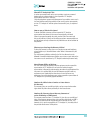
3. Installation
3.1. Unpacking the Components
A COMBI PAL system is shipped in one box. The box contains the X-,Y-axes
assembly, the Injection Unit, the heated Agitator, the Keypad Terminal, GC
mounting kit (optional), connecting cables, power supply, (heated) Syringe
kits, Tray Holders, Trays, Wash Station assembly, Safety Guard and
miscellaneous parts.
1. Open the box and first remove the accessory boxes and the Injection Unit
before attempting to remove the X-, Y-axes assembly;
2. Carefully lift the X-,Y-axes assembly and remove it from the box. Hold
the Y-axis in place while the assembly is being removed from the box.
Set the X-,Y-axes assembly on a bench;
3. Unpack the remaining small boxes and any other accessories;
4. When placing the COMBI PAL onto a GC, make sure that no objects
interfere with either the Y-axis or the Injection Unit throughout the entire
range of potential movement.
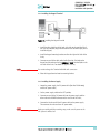
3.2 Assembling the COMBI PAL
note
During headspace operation, the syringe is cleaned after each injection with
clean, inert gas (e.g. N2 or He). Therefore, a 1/8 inch gas supply line must
be available close to the COMBI PAL.
1. First mount the correct GC mounting kit onto the GC;
2. Loosen the two mounting clamp Torx screws of the vertical legs;
3. Place the X-, Y-axes assembly on top and fit the mounting kit legs into the
groove in the X- axis. Be sure that the clamps fit completely into the
grooves. Alternately tighten the two Torx screws until the legs are firmly in
place;
4. Double check whether the leg claws are correctly attached to the X-axis
(see Fig. 9).
Figure 9. Attachment of Mounting Claws
35
COMBI PAL / LHX PAL
PAL COMBI-xt / PAL LHX -xt
User Manual
Installation and Operation
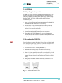
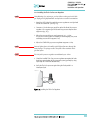
3.2.1. Installing the Injection Unit
note
Installation of the Injection Unit should be done carefully. When installing it
for the first time, have someone hold it in place while the mounting screws
are inserted.
Figure 10. Attaching the PAL Injection Unit
1. Remove the three Torx mounting screws A, B, and C, used to fix the
Injection Unit to the Y-axis;
2. Connect the ribbon cable A protruding from the front end of the Yaxis to the corresponding connector on the Injection Unit (see Fig. 11);
Figure 11. Connecting the Injection Unit Ribbon Cable
36
COMBI PAL / LHX PAL
PAL COMBI-xt / PAL LHX -xt
User Manual
Installation and Operation
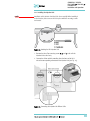
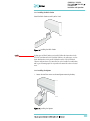
3. Hold the Injection Unit in place against the Y-axis. Make sure the two
locating pins on the Y-axis fit into the two guide pin holes on the Injection
Unit;
4. Place one of the screws onto the end of the supplied Torx driver. Slide the
clear plastic cover on the Injection Unit all the way to the top. Locate the
three large holes in the black anodized frame attached to the Z-axis inside
the Injection Unit. Slide the frame upwards until the top hole is centered
on the top threaded hole at the end of the Y-axis. Insert and
securely tighten the Torx screw A. (See Fig. 12.);
Figure 12. Inserting the Injection Unit Mounting Torx Screws
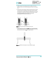
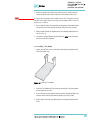
5. Install the two remaining Torx screws B, C in the left and right mounting
holes, respectively. It may be necessary to move the elastic cord slightly to
the left to insert the Torx screw C into the right-hand hole.
Figure 13. COMBI PAL with Injection Unit and Standalone Supports
37
COMBI PAL / LHX PAL
PAL COMBI-xt / PAL LHX -xt
User Manual
Installation and Operation
3.2.2. Installing the Keypad Terminal
Figure 14. Installing the Keypad Terminal
1. Install the safety shield on the left and right sides to the outside of the Xaxis. Use the provided, longer thumbscrew on the side where you plan to
install the keypad;
2. Install the Keypad mounting bracket on either the right or left side of the
X-axis;
3. Connect one end of the white coiled cable (Part No. SS8J-700) to the
Keypad and the other end to the TERMINAL (SER3) interface jack on the
rear side of the X-axis. For details see Figures 19 or 20;
note
Do not interchange the Terminal with LAN cable connectors.
4. Place the Keypad terminal onto its mounting bracket.
3.2.3. Installing the Power Supply
1. Locate the power supply, the DC power cable (Part No. RS3M-2000),
and the AC power cable;
2. Set the power supply switch to the OFF position;
3. Connect one end of the DC power cable to the power supply and the
other end to the POWER connector at the rear side of the X-axis;
4. Connect the female end of the AC power cable to the power supply.
Then connect the male end to an AC power outlet.
note
Before proceeding with the remaining steps, make sure the power to the
PAL System is switched off.
38
COMBI PAL / LHX PAL
PAL COMBI-xt / PAL LHX -xt
User Manual
Installation and Operation
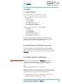
3.2.4. Installing the Flush Gas Pressure Regulator
note
Safety Warning: Use an inert gas, such as helium or nitrogen, for the flush
gas. Hydrogen is highly flammable and explosive at certain concentrations.
1. Attach the OUT-side of the supplied pressure regulator at rear right hand
side of the COMBI PAL. (See Fig. 15.);
2. Connect a 1/8 inch clean gas supply line to the IN-side of the pressure
regulator. Use a separate gas line to avoid any pressure drop on other
equipment (e.g. GC);
3. Adjust the pressure of the gas supply source to 1.0 − 1.5 bar.
If a gas line is teed-up from an installed gas chromatograph, the preset
secondary pressure will be approx. 5 bar;
4. Adjust the COMBI PAL gas pressure regulator to approx. 0.5 bar;
note
Pressure higher than 0.5 bar will not yield higher flow rates through the
heated syringe. The syringe needle is the point of flow restriction in the
gas flow system.
note
The body of the pressure regulator can withstand up to 10 bar.
5. Check the installed Flush Gas pressure regulator connections for leaks.
Avoid any contamination of the pneumatic system (gas flow) by using
liquid soap or similar leak detection aids;
6. Verify the Flush Gas pressure again during the flush period in a
Headspace Cycle.
Figure 15. Installing the Flush Gas Regulator
39
COMBI PAL / LHX PAL
PAL COMBI-xt / PAL LHX -xt
User Manual
Installation and Operation
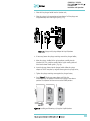
3.2.5. Installing the Wash Station
Attach the Wash Station assembly to the X-axis.
Figure 16. Installing the Wash Station
note
If other types of Wash Stations are installed, follow the instructions in the
HTS PAL User Manual for the Fast Wash Station or for other types, such as
Active Washstation, in the specific Addendum of the PAL User Manual.
Observe safety measures if a waste line has to be installed in combination
with a gas chromatograph. Do not position the waste line above a heated
zone.
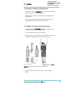
3.2.6. Installing the Agitator
1. Loosen the two Torx screws on the two Agitator mounting brackets;
Figure 17. Installing the Agitator
40
COMBI PAL / LHX PAL
PAL COMBI-xt / PAL LHX -xt
User Manual
Installation and Operation
2. Attach the Agitator to the left or right end of the X-axis. Install it with the
mounting clamp teeth fit into the grooves on the bottom of the X-axis;
note
Do not position the Agitator in the middle of the X-axis. The Agitator must be
installed on the right or left side. Crossing-over the Agitator with a 20 ml vial
would cause a collision.
3. Be sure that the clamps fit completely into the grooves. Alternately tighten
the two Torx screws until the two mounting clamps are firmly in place;
4. Double check whether the Agitator clamps are correctly attached to the Xaxis. (See Fig. 9.);
5. Connect the supplied Agitator control cable from AUX1 to the connector
on the rear side of the Agitator.
3.2.7. Installing a Tray Holder
1. Loosen the two Torx screws on the two mounting clamps located on top
of the Tray Holder legs;
Figure 18. Installing a Tray Holder
2. Install the Tray Holder with the mounting clamp teeth fit into the grooves
on the bottom of the X-axis;
3. Be sure the clamps fit completely into the grooves. Alternately tighten the
two torx screws until the two mounting clamps are firmly in place;
4. Double check if the two Tray Holder clamps are correctly attached to the
X-axis.
41
COMBI PAL / LHX PAL
PAL COMBI-xt / PAL LHX -xt
User Manual
Installation and Operation
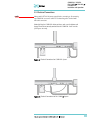
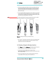
3.3. Electrical Connections
note
Always switch OFF the PAL power supply before connecting or disconnecting
any COMBI PAL accessories cable! Do not interchange the Terminal with
LAN cable connectors.
Before defining the COMBI PAL object positions, make sure the Agitator and
Keypad Terminal are correctly connected to the COMBI PAL X-axis rear side.
(See Figures 19 or 20).
Figure 19. Electrical Connections for COMBI PAL System
Figure 20. Electrical Connections for PAL COMBI-xt System
42
COMBI PAL / LHX PAL
PAL COMBI-xt / PAL LHX -xt
User Manual
Installation and Operation
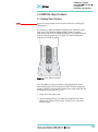
4. COMBI PAL Object Positions
4.1. Defining Object Positions
note
Remove the Syringe Adapter from the Injection Unit before performing the
following steps.
The objective is to define the Reference Positions for all COMBI PAL Objects.
Make sure the Tray Holder(s), Agitator and Wash Station are properly
mounted to the PAL X-axis. The following description is an example of how to
teach the reference position for a Tray Holder. The described procedure is
common to all COMBI PAL Objects.
Figure 21. Object Reference Position
For a Tray Holder, the reference position is a hole (slightly larger than the
lower needle guide) in the base plate of the holder. The lower needle guide
should be centered in the hole with the bottom of the needle guide flush with
the bottom of the base plate (see Fig. 21).
1. Switch ON the PAL power supply;
2. Observe the keypad display. The model name COMBI PAL will display
along with the software version number. The Job Queue menu screen
will then display;
43
COMBI PAL / LHX PAL
PAL COMBI-xt / PAL LHX -xt
User Manual
Installation and Operation
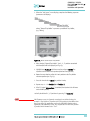
3. When the "Job Queue" menu displays, complete the following sequence
(common to all objects):
where "Named Tray Holder" represents a predefined Tray Holder,
(e.g. THldr1);
Figure 22. Menu Screen Object Tray Holder
4. After selecting "Named Tray Holder", the X-, Y-, Z- positions associated
with the object will be displayed (see Fig. 22);
5. Highlight item Position X with the cursor bar and press ENTER. The
Injection Unit will move to the previously defined X-axis position;
6. Rotate the outer knob to adjust the X-axis position to the Tray Holder
reference position (see Fig. 21);
7. Press the inner knob to ENTER the position X value;
8. Repeat steps 5 – 7 for Position Y and Position Z;
9. If the F3 button "Moveto Zero" is activated, the Injection Unit will move
to the HOME position;
10. Verify the defined X-, Y-, Z-positions by pressing F1 "Check Pos".
note
PAL Firmware verson 3.0.X permits correcting for an inclined surface, for
example a Tray Holder or Tray where the Z-axis position in front differs from
the rear position. For applications such as the PAL MALDI Option, perfect
alignment of the MALDI tip is vital. This compensation for the Z-axis position
is provided in the firmware class “Tool”.
44
COMBI PAL / LHX PAL
PAL COMBI-xt / PAL LHX -xt
User Manual
Installation and Operation
For the device “PAL MHE Tool” the PAL Firmware Object Class “Tool” is also
required. See specific Addendum to PAL User Manual.
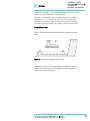
The release of PAL Firmware version 4.1.X makes possible the correction of
all three axes, X-, Y-, Z, in the firmware class “Tray.” The correction of the
inclination can be made for a tilted Tray in the direction of the row and/or
the column. Teaching is possible in the ”Utilities” section by using the path:
Menu/Utilities/ Trays.
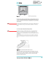
Figure 23 illustrates possibilities of correction. Details for teaching are given
below.
Figure 23. Inclined Tray, Corrections for X-,Y-,Z-Axes
Note that these functions are not available for the GOMBI PAL if operated
solely on PAL Firmware version 2.4.X or higher, but neither with firmware
version 3.X.X. nor with version 4.X.X.
45
COMBI PAL / LHX PAL
PAL COMBI-xt / PAL LHX -xt
User Manual
Installation and Operation
4.2. Description of Object Positions
4.2.1. Tray Holder (e.g. THldr1)
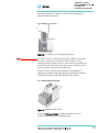
Figure 24. Tray Holder Reference Position
For a Tray Holder, the reference position is a hole in the base plate of the
Holder. The lower needle guide should be centered in the hole with the
bottom of the needle guide flush with the bottom of the base plate.
Figure 24 shows the example of a Tray Holder for a single Tray, e.g. “THldr1”
for “Tray 1” with Tray Type “VT98”.
4.2.2. Trays
In general it is not necessary to teach a Tray position. The Tray Holder has a
teaching position, as described above. A Tray is assigned to the Tray Holder.
The numbers (values) for the relevant items are stored in the firmware object
“Tray”. To complete the combination of a Tray Holder and a Tray, it is
necessary to assign the corresponding “Tray Type” to the “Tray.”
The “Tray Type” contains the geometric data for the Tray and information
such as how many samples are in a row and a column in the Tray. A Tray
Type defines the pattern and sampling sequence of sample location within a
Tray. For details see below.
As described above, the Tray is physically placed in the Tray Holder, the
firmware assigns the Tray to the Tray Holder and the Tray Type to the Tray.
This is routine procedure as long as no special circumstances need be
considered, such as customized Trays or Tray Types.
PAL Firmware version 4.1.X now makes a correction possible if the Tray
surface is not exactly horizontal and planar but is inclined in one or more
axes. At version 4.1.X this is standard and a dialog window pops up the
moment the Tray has been checked-out at the corners to verify vial positions
and heights. How to correct a possible inclination is explained below.
46
COMBI PAL / LHX PAL
PAL COMBI-xt / PAL LHX -xt
User Manual
Installation and Operation
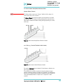
Figure 25. Demonstrating a possible Inclination of Tray in X-,Y-,Z-Axes.
4.2.2.1. Definition of a Tray Row and Column
The PAL System defines Rows and Columns by the order in which samples
are treated. A “Row” is not associated with an X- or Y-axis. The definition is
visualized below with Tray Type VT32 and DW96:
Figure 26. Tray Type VT32
Figure 27. Tray Type DW96
4.2.2.2. Correction for Sample Position in X-, Y- or Z-Axes
PAL Firmware Version 2.X.X.
The following description of the correction is done by using the path to the
“Utilities” section.
After selecting the Utilities function “Trays”, verify whether the Tray Type
assigned corresponds to the Tray placed into the Tray Holder. If this is
verified, the vial positions can be checked at the three corners of the Tray.
This is activated by the “F3” function key.
47
COMBI PAL / LHX PAL
PAL COMBI-xt / PAL LHX -xt
User Manual
Installation and Operation
Figure 28. Utilities Function “Trays”
The Injection Unit moves to Tray position no. 001. With the help of the
inserted syringe is it possible to check the optimized position of the needle tip
matching with the vial or well position.
In case the position is off, make corrections in X-, Y- or Z-positions.
Continue with function key “F3” to move to the next corner to verify this
position. If the position matches, continue with function key “F3” to move the
unit to the third corner position.
If a deviation of the ideal position is observed in second or third corner, the
corrections have to be made on the position no. 001. The offset is bound to
position no. 001.
note
Activating one of the parameters Offset X-, Y-, or Z-axis at the positions of
second or third corner can bend the syringe needle.
4.2.2.3. Correction for Inclination in X-, Y- or Z-Axes
PAL Firmware Version 4.1.X or higher
The following description of the correction is done by using the path to the
“Utilities” section.
After selecting the Utilities function “Trays”, verify whether the Tray Type
assigned corresponds to the Tray placed into the Tray Holder. If this is
verified, the vial positions can be checked at the three corners of the Tray.
This is activated by the “F3” function key.
48
COMBI PAL / LHX PAL
PAL COMBI-xt / PAL LHX -xt
User Manual
Installation and Operation
A dialog window opens, displaying a note to “Adjust offset X-, Y-, Z for
position 001”. Continuing in this dialog will provide the user the opportunity
to adjust all three axes perfectly by the top of the vial. Please note that this
step is only valid for position number 001.
Figure 29. Adjusting “Offset X,Y,Z” for Tray Position 001
To check the next corner of the Tray, activate function key “F3” again, example
Tray Type “VT32”, position 008.
The next information provided by the pop-up window asks to correct a
possible inclination of the “Row”. Continuing the dialog provides the user the
opportunity to adjust the three axes perfectly to match the vial top – or in
case of a well-plate, the top of the plate.
Figure 30. Adjusting Row Inclination at second Tray corner position
The last step will be to move to the next corner of the Tray by again activating
function key “F3”. This will be position 32 in the example of Tray Type “VT32”.
A possible inclination of the Tray column can be corrected in the same
manner as described above.
49
COMBI PAL / LHX PAL
PAL COMBI-xt / PAL LHX -xt
User Manual
Installation and Operation
Figure 31. Adjusting Column Inclination at Third Tray Corner Position
The three corner points are now adjusted for a possible inclination of the Tray
in any axis. A possible deviation from an ideal axis position for the other vials,
caused by variance from the horizontal, is interpolated by the system without
further teaching.
note
For routine work using standard vials it is not necessary to compensate for a
possible inclination as long as the vial detection is within the “Z-Tolerance”
range.
4.2.3. Wash Station: Wash1/Wash2 Reference Point
note
If positions of other types of Wash Stations have to be taught, follow the
instructions in the HTS PAL User manual for the Fast Wash Station or for
other types, such as Active Washstation, in the specific Addendum of the PAL
User Manual.
Observe safety measures if a waste line has to be installed in combination
with a gas chromatograph. Do not position the waste line above a heated
zone.
Figure 32. Wash Station Wash1/Wash2 Reference Point
For the Wash Station, the reference positions are the two holes in the wash
vial caps (see Fig. 32, Wash1 and Wash2). The lower needle guide should be
centered in these holes with the bottom of the lower needle guide lightly
touching the surface of the caps.
50
COMBI PAL / LHX PAL
PAL COMBI-xt / PAL LHX -xt
User Manual
Installation and Operation
4.2.4. Wash Station: Waste/Waste2 Reference Point
Injectors (Waste / Waste2 )
note
The Waste positions represent an "Injector" within the PAL software. It is
defined in the Object class "Injectors".
For Waste / Waste2 the reference positions are the two holes in the wash
vial caps (see Fig. 33). The lower needle guide should be centered in these
holes with the bottom of the lower needle guide lightly touching the surface
of the caps.
Figure 33. Wash Station Waste/Waste2 Reference Position
4.2.5. Vials (e.g. “Standard” Position in Wash Station)
Figure 34. Wash Station Standard Reference Position
The position “Standard” on the Standard GC Wash Station is defined in the
PAL Firmware class “Vials”.
This position can be used for a standard, an internal standard, a reagent
solution, a calibrator solution or any other type of solution. The advantage to
the user is that a large quantity of solution is available and can be defined by
“Job” (conventionally known as “Sample List” or “Sequence” in other
systems).
51
COMBI PAL / LHX PAL
PAL COMBI-xt / PAL LHX -xt
User Manual
Installation and Operation
The reference position is the hole in the vial cap. Teaching this position is
identical for Wash or Waste vials.
4.2.6. Injectors (e.g. GC-Inj1)
Figure 35. GC Injectors (e.g. GC Inj1) Reference Position
note
For certain GC models, centering rings are provided with the GC mounting
kit. If such a centering ring is available, it should not only be used for
teaching the injector position but also for routine work. The ring stabilizes the
needle guide of the PAL Injection Unit at the moment of needle penetration.
It acts as a guide tool and prevents needle bending.
For the GC Inj1 (GC Inj2) the reference position is the appropriate GC
Injection port. The lower needle guide should be centered on the port with
the bottom of the lower needle guide lightly touching its surface.
4.2.7. Agitator Reference Position
Figure 36. Agitator Reference Position
The Agitator Reference Position is located as indicated in Figure 36.
To define the position, complete the following steps:
52
COMBI PAL / LHX PAL
PAL COMBI-xt / PAL LHX -xt
User Manual
Installation and Operation
1. When the "Job Queue" menu is displayed complete the following
sequence;
2. Select "AgiHldr" and scroll to Access Path / Restore Path;
3. If the Agitator is located on the left side, choose AgiOpnL / AgiClsL
If the Agitator is located on the right side, choose AgiOpnR / AgiClsR;
note
Steps 2+3 are obsolete beginning with Firmware version 2.2.0 or higher.
4. Open the white Agitator cover manually and block it open with a
screwdriver, fitting it into the side of the cover;
5. Insert a 20 mL vial in sample position No. 1;
6. Attach the red vial transport ring to the lower needle guide;
7. Define the X-, Y-, Z- positions common to all objects as described in topic
4.1. The reference position is located at the hole in the steel vial cap. The
lower needle guide should be centered on the vial cap and should touch
the cap;
8. Remove the screwdriver and close the Agitator cover.
note
After all positions have been set, perform a firmware backup of the existing
configuration by using the PAL Loader software. For instructions, see below.
53
COMBI PAL / LHX PAL
PAL COMBI-xt / PAL LHX -xt
User Manual
Installation and Operation
5. Syringes
5.1. Selecting Syringes
The standard COMBI PAL is shipped with two syringe kits:
One PAL SyrGC10µL Kit GC Syringe 10 µL for COMBI PAL,
consisting of:
1 pc syringe adapter
1 pc plunger holder
2 pcs syringe SYRC L10-26S-AS or
2 pcs syringes SYRC L10-23S-AS
(in combination with Shimadzu GC.)
1 PAL SyrHS2.5mL Kit HS Syringe 2.5 mL for COMBI PAL,
consisting of:
1 pc syringe heater
1 pc plunger holder
2 pcs syringe SYRC HS2.5-23-5 or
2 pcs syringe SYRC HS1.0-23-5
(in combination with a Varian GC)
The supplied syringe kits cover the standard liquid and headspace GC
injection techniques. However, certain applications may require different
syringe sizes. Consult "COMBI PAL Accessories" for detail.
5.2. Syringe Priming (for Liquid Syringe Types only)
It is critical that syringes be primed before beginning sample preparation.
Prime every liquid syringe first manually before inserting into the PAL system.
Afterwards, the syringe can be primed and tested by using the Utility function
"Clean Syr".
5.3 Installing a Syringe for Liquid Injections
note
Before a syringe is inserted, the position “Change Syr” should first be
verified. The position “Change Syringe” should not be located above an
object where the needle could collide with a vial, as for example.
Path:
Menu/Utilities/Syringe/function key “F3” “Change Pos”.
Move the PAL Injection Unit to a location where a collision cannot occur by
selecting the X- and Y- axes. The value for the Z-axis is given as a default and
a change of this position is not necessary in standard operation.
1. Select Menu and press F1/Chang Syr. The Injection Unit will move to a
location that will facilitate installation of the syringe;
54
COMBI PAL / LHX PAL
PAL COMBI-xt / PAL LHX -xt
User Manual
Installation and Operation
2. Place the blue plunger holder into the injection unit;
3. Place the syringe in the appropriate syringe adapter. Pull the plunger out
to approximately 20% of its length. (See Fig. 37.);
Figure 37. Syringe and Syringe Adapter for Liquid Injections
4. If necessary, loosen the plunger retaining screw in the plunger holder;
5. Move the syringe, installed in the syringe adapter, partially into the
Injection Unit. First, guide the needle into the upper needle guide and
then into the lower needle guide. (. Fig. 38);
6. Insert the plunger button into the plunger holder. Allow the syringe
adapter to "click" into place by magnetic force against the syringe carrier;
7. Tighten the plunger retaining screw against the plunger button;
8. Press "Home". The plunger moves down until it hits the
mechanical stop. This position is stored as the syringe’s zero volume
position. The Injection Unit then returns to the HOME position.
Figure 38. Installing and Removing a Syringe for Liquid Injections
55
COMBI PAL / LHX PAL
PAL COMBI-xt / PAL LHX -xt
User Manual
Installation and Operation
5.4. Removing a Syringe for Liquid Injections
1. Select "Menu" and press F1/Chang Syr. The Injection Unit will move to a
location that facilitates removal of the syringe;
2. Loosen the plunger retaining screw. Move the plunger slightly out of the
plunger holder;
3. Pull the syringe adapter out and then carefully upward to remove the
syringe adapter, with the syringe, from the Injection Unit.
5.5. Installing a Syringe for Headspace Injections
1. Select Menu and press F1/Chang Syr. The Injection Unit will move to a
location that facilitates installation of the syringe;
2. Fit the red plunger holder onto the plunger button;
3. Place the syringe in the appropriate heated syringe adapter. Pull the black
plunger out to approximately 20% of its length. (See Fig. 39.);
Figure 39. Headspace Syringe and heated Syringe Adapter
4. If necessary, loosen the plunger retaining screw in the red plunger
holder;
56
COMBI PAL / LHX PAL
PAL COMBI-xt / PAL LHX -xt
User Manual
Installation and Operation
5. Lift the lower needle guide, sliding it into the upper needle guide. Insert
the syringe needle tip and match the magnetic pins of the syringe holder
with the counter positions on the syringe slider. Let the lower needle
guide return slowly and make sure the needle tip does not catch on the
guide. (See Fig. 40.);
6. Press the heated cartridge firmly against the Z-axis slider to ensure that the
Syringe heater unit engages. Move the plunger up (plunger holder) until
the thread of the screw catches the thread of the plunger bushing. Tighten
the screw to fix the plunger holder. (See Fig. 40.);
note
The clamp provided with the Headspace syringe kit must only be installed
with a 5 mL HS-syringe. See note enclosed in the syringe kit.
Figure 40. Installing and Removing a Headspace Syringe
7. Press "Home". The plunger moves down until it hits the mechanical stop.
This position is stored as the syringes zero volume position. Then the
Injection Unit returns to the HOME position.
5.6. Removing a Syringe for Headspace Injections
1. Select "Menu" and press F1/Chang Syr. The Injection Unit will move to a
location that facilitates removal of the heated syringe adapter;
2. Unscrew the red plunger holder from the plunger bushing.
Move the black plunger slightly down to gain some space to be able to lift
out the syringe cartridge;
3. Pull the syringe adapter out and then carefully upward to remove the
syringe adapter, with the syringe, from the Injection Unit;
57
COMBI PAL / LHX PAL
PAL COMBI-xt / PAL LHX -xt
User Manual
Installation and Operation
Figure 41. Removing a Headspace Syringe from the Heated Syringe Adapter
4. Unscrew the white plastic retainer;
5. Place the supplied gray plastic tube over the needle. This plastic tube
protects the syringe needle at shipment, but it can be used as a syringe
removal tool;
6. Using the gray plastic tube, push the Headspace Syringe through the
heated Syringe Adapter.
note
Gastight Headspace syringes have very tight plungers when new. After a
short operating time at elevated temperature, the plunger tip adjusts its
diameter. Should the syringe be used later at lower temperatures, there will
be a risk of leakage. The polymer tip never expands at lower temperatures.
Therefore, a particular Headspace syringe should always be used at the
same or higher temperatures.
6. Interfacing the COMBI PAL to Other Devices
6.1. Synchronization and Output Signals
Synchronization Signals (Sync Signals) are inputs that tell the COMBI PAL
when to wait or proceed with a sample-processing step. Output Signals
(Out Signals) are sent from the PAL to external devices to indicate status or
completion of particular processing steps. These signals are classified as
Objects. Physical Events (e.g. TTL-In1) are also Objects and may be assigned
to named signals. PAL Cycles require that certain signals such as "Start",
"Inject", and "Injected" be defined. See the next table below for the PAL
Events and signal assignments associated with the standard PAL "GC-Inj",
"HS-Inj" and "GC-Dual" cycles.
Certain types of integration of the PAL system into data handling or control
software, such as ChemStation, Xcalibur, Galaxie or Chromeleon, accomplish
synchronization of the Ready/Start signal done directly via software control
58
COMBI PAL / LHX PAL
PAL COMBI-xt / PAL LHX -xt
User Manual
Installation and Operation
(RS232/LAN). A synchronization cable is not required and the Sync Signal
“Start” must be set to “Immediat”.
To assign a physical Event (e.g. SW-Out 1) to an existing signal Object
("Injected"), complete the following menu selections:
PAL Systems are shipped with all Cycle events pre-defined, as shown in the
table below. If a different physical signal needs to be used, then it will be
necessary to assign a new Event to the Object signal.
If a signal is to be ignored, then its corresponding Event must be set to
"Immediat".
Standard Assignment for
COMBI PAL Injection Cycles
Description
Default
Events
Start JobQueue (Sync Signal)
Start a Job Queue (Job).
Prerequisite is a defined “Job” with
a method assigned. Useful for
automated, unattended, timed
sampling.
Immediat
Start
Start a cycle (Input from GC or data
Immediat 1
system)
(Sync Signal)
Start2
(Sync Signal)
Continue the cycle “GC-Dual” for
the second sample
Immediat
(Ignore)
Inject
(Sync Signal)
Inject
READY to INJECT
Immediat
(Ignore)
Inject2
(Sync Signal)
Inject the second sample for “GCDual” cycle
Immediat
(Ignore)
Injected
(Out Signal)
Activated at the moment the
sample has been injected
SW-Out1
Injectd2
(Out Signal)
Activated at the moment the
second sample has been injected
Off
Running
(Out Signal)
Active as long as the Job Queue is
being processed and the PAL is not
in an error state
Off
INTERFACE
1 Pin #
7
8(GND)
3
4
1) If used to synchronize with Sync cable, change setting to “TTL-In1”
If an item of the class “Sync Signal” is assigned to an output signal, such as
“TTL-In1”, then this TTL contact must be defined as either “Active High” or
“Active Low”, as expected by the GC system. This is defined in the PAL
Firmware class “Events”.
59
COMBI PAL / LHX PAL
PAL COMBI-xt / PAL LHX -xt
User Manual
Installation and Operation
Select the corresponding item and set the mode accordingly.
The setting is provided with the schematic description of the GC Sync Cable
supplied with the specific GC Mounting Kit.
7. PAL System Software
7.1. PAL Loader Software
The purpose of PAL Loader Software is to create a backup file of the complete
PAL System Firmware. The core software (firmware) and all PAL Firmware
Objects, including all settings (Items), the local methods, and jobs are saved
in one file.
The PAL Loader software has a second function of loading the firmware or a
complete backup file to a PAL system.
The PAL Loader software has always been a part of the PAL System.
The following PAL Loader Software versions are in use:
- PAL Loader Version 1.0.1
- PAL Loader Version 1.1.1
A new PAL Loader software, “Loader” version 2.1.1 (or higher), has been
developed for the PAL-xt system.
The PAL-xt system requires PAL Firmware 4.1.X or higher, which calls for the
new “Loader” software.
The new PAL Loader Software is backwards compatible. The software
can be used for all PAL Firmware versions.
The name of the *.exe file has been changed intentionally to avoid conflicts
when old and new versions are installed on the same computer:
•
PAL Loader version 1.1.1: PALLOAD.exe
PAL Firmware version up to and including 3.X.X
•
PAL Loader version 2.1.X: PALoader.exe
PAL Firmware version as of 4.1.X
but backwards compatible with lower versions.
Details are described in: “Addendum to PAL User Manual, PAL Loader
Software Version 2.1.X, Installation and Operation”.
60
COMBI PAL / LHX PAL
PAL COMBI-xt / PAL LHX -xt
User Manual
Installation and Operation
7.2. PAL Object Manager Software
The PAL Object Manager software is used to load a new PAL Firmware Object
to a system after a new module (hardware module) has been added to the
PAL System.
The PAL Object Manager software is the software used to handle the so-called
PAL Object List.
The software version 2.2.1 or higher has been developed for the PAL-xt
System that, in addition to serial communication, also permits LAN
communication (TCP/IP). The software is backwards compatible and can be
used for all PAL Firmware versions.
The PAL Object Lists have to match the corresponding PAL Firmware version,
as shown in the list below:
•
PAL System
Firmware Versions 2.X.X
PAL Object Lists Rev. K (or higher)
•
PAL System
Firmware Version 3.0.X
PAL Object Lists Rev. K (or higher)
See specific Object Lists for this FW Version 3.0.X.
•
PAL-xt System
Firmware Version 4.1.X (or higher)
PAL-xt Object Lists Rev. B (or higher)
The two Object Lists for the PAL and PAL-xt Systems can be loaded with the
same PAL Object Manager software. This simplifies the handling in cases
where the PAL and PAL-xt Systems are in use within the same working
environment.
Detailed information is available in the ‘Addendum to PAL User Manual PAL
Object Manager Software’.
61
COMBI PAL / LHX PAL
PAL COMBI-xt / PAL LHX -xt
User Manual
Installation and Operation
8. Establishing Communication with Computer
The PAL System allows a serial communication protocol with a PC. As a new
feature, the PAL-xt System provides LAN communication, also referred to as
“TCP/IP” or “Ethernet”.
The PAL-xt System requires a dedicated “APR Control-xt ” board and PAL
Firmware version 4.1.X or higher.
8.1 COM Port Settings
The port settings are normally defined in:
Windows\Control Panel\Device Manager\Ports.
The standard settings for the serial communication are shown in Figure 45.
It is important to understand that the application (e.g. PAL Loader Software)
does actively set the communication parameters, and the baud rate is set
for optimized use.
Figure 42. COM Port Settings
A quick way to check whether serial communication with the PAL System can
be established is to use the PAL Loader software. For details see “Addendum
to PAL User Manual PAL Loader Software”.
62
COMBI PAL / LHX PAL
PAL COMBI-xt / PAL LHX -xt
User Manual
Installation and Operation
8.2 Setting up LAN Communication
Select the firmware “Communication” class by the following path:
Menu/ F3-Setup/Communication
note
Menu/ F3-Setup/Communication
See detailed description below under point 10.
The system automatically searches for the MAC address when the “Setup
Communication” window is accessed.
Figure 43. Reading the MAC Address from the Ethernet Communication Port
This search for and reading of the MAC address takes approximately 10 to 15
seconds. If successful, the MAC Address is stored in the system firmware and
can be viewed on the terminal as follows.
Figure 44. PAL-xt Communication Settings
Pressing function key “F1”, “Set Comm” sets the selected communication
mode. The same is achieved by pressing “ESC” or “Home”.
63
COMBI PAL / LHX PAL
PAL COMBI-xt / PAL LHX -xt
User Manual
Installation and Operation
Figure 45. Setting Communication Mode
64
COMBI PAL / LHX PAL
PAL COMBI-xt / PAL LHX -xt
User Manual
Installation and Operation
8.2.1. Explanations for the various settings for the
Communication Protocol
Parameter
CommPort
Explanation
Setup for serial (SER1) or LAN
communication.
DHCP
= Dynamic Host Configuration
Protocol.
If set to “Off”, the IP address is
provided by the user, see
IPAddr1 to 4. The user can ask
the network administrator for a
suitable IP address.
If set to “On”, an IP address is
dynamically sought throughout
the provided network.
IPAddr1 to 4
Enter the IP address divided into
four blocks, example IP default
Address: 192.168.0.1.
SubNet1 to 4
SubNet mask for network
configuration.
TCPPort
This parameter is read only, no
changes possible.
StdGateway
1 to 4
If Gateway is used in network,
the Gateway IP address (switch,
hub) has to be entered.
MACAddr1 to6
The unique MAC Address for the
PAL-xt System is read and
entered into this PAL-xt
communication protocol.
This is a read only parameter
field.
Remarks
If serial communication is
selected, all other parameters in
PAL-xt Firmware
“Communication” class are
ignored.
It is advisable to use a fixed IP
address, set the “DHCP”
parameter to “Off”.
In this mode the PAL-xt System
always has the same fixed IP
address. Troubleshooting is
easier for the network
administrator.
See also special remarks below.
The IP address is a fixed PAL-xt
System address. The IP address is
often provided by the network
administrator.
The SubNet mask must be
provided by the network
administrator.
The network administrator must
be informed about this setting.
The port must be cleared of
firewall protection to enable
communication.
Gateway is used if independent
networks need to communicate
interactively. Communication
within the network is provided by
a hub or switch, defined as
“Gateway”.
The MAC address is provided by
the Ethernet communication
hardware. The address is also
visible beside the read-out from
the terminal on the label affixed
to the Ethernet module on the
PCB “APR Control-xt”.
65
COMBI PAL / LHX PAL
PAL COMBI-xt / PAL LHX -xt
User Manual
Installation and Operation
8.2.2. Special Remarks to the above listed Parameters
DHCP:
If “DHCP” mode is active, an automatic search for the IP address is activated.
If a free IP address is found, the communication between the PAL-xt System
and the network becomes established. The new IP address (found through
“DHCP” search) is immediately entered into the PAL-xt Communication
protocol as seen from the local terminal. The parameters “IPAddr1 to 4” are
not updated until one opens the communication menu again.
The Setup for the PAL Loader software requires entering the IP address or
hostname. The dynamically provided IP address is displayed on the local
terminal. As an alternative, the following setup procedure can be used:
Prerequisite: PAL-xt setting in “Communication” class: DHCP = On.
Open the “Setup” window and enter the following name in the “Hostname
or IP Address” field: CXXXXXX. The “Xs” being the last six characters of the
MAC address, which is known from the parameter “MacAddr4, MacAddr5,
and MacAddr6.
If a MAC address only consists of one character, insert a 0 in front of it. If, for
example, MacAddr4=BA, MacAddr5=35 and macAddr=3, enter CBA3503 and
not CBA353.
8.3 Troubleshooting for Serial or LAN Communication
Both communication protocols are described in detail in the “Addendum to
PAL User Manual PAL Loader Software”.
66
COMBI PAL / LHX PAL
PAL COMBI-xt / PAL LHX -xt
User Manual
Installation and Operation
9. Special Functions
This section describes special functions which can be activated by the “PAL
Extended User Mode”.
The purpose of having two software access levels is to display discrete items
and sections of the firmware at each level. Settings which need to be done
rarely, perhaps at the time of installation of the PAL System, are hidden at
level 1(User Level) and revealed at level 2 (Extended User Level). This also
protects the PAL System in group use. Nevertheless, the important points
should be known by the user and are described below.
9.1. How to Access “Extended User Mode”
Extended User Mode can be accessed by the following path:
The above path as shown is an abbreviation for the following steps:
•
Menu/ scroll the cursor to “Setup” /
•
Press function key “F3” /
•
Activate “Setup” by pressing the center of the selector knob.
In this PAL User Manual or in technical notes, only the following will be
referred to:
Menu/F3-Setup/.
67
COMBI PAL / LHX PAL
PAL COMBI-xt / PAL LHX -xt
User Manual
Installation and Operation
9.2. Section “F3-Setup”
The path to access this section is shown below.
This “Setup” section at the Extended User Level provides various options to
access other classes which are not visible at the User level. Some classes are
known but may show some new items. Details are described below.
Figure 46. Selecting “Setup” in Extended User Mode
Object
Description
Ident
The “Identification” of the system provides the opportunity to assign Users, site,
and system names. The serial number of the PAL System can be entered at this
level. Remark: After loading a fresh PAL Firmware Backup file, the SNo. Is
displayed as “XXXXXX”.
Access can be selectively opened or limited to different users for the “Job”,
“Method” or “Setup”.
The “Beep” sound can be adjusted to specific needs. For safety reasons it is
advisable to keep the default settings, especially the “Warn Move,” turned ON to
signal the start of the PAL System to the user.
The PAL internal clock can be set.
Remark: If the clock is fast, reset all items, from “Year” to “Seconds” and use the
mandatory function key “F1” “Set Time”.
The communication mode serial or LAN can be selected and conditions are
defined.
For details see above point 8 or Addendum PAL Loader Software.
Basic parameters can be predefined for specific needs. Details see below.
Basic service tests can be activated. Details see below.
Accessing the PAL Firmware class “Objects” in the Extended User mode provides
more detailed possibilities for object items. At this level an Object can be copied
or deleted by using the specific function keys. This provides quick access to add
e.g. a second or third injector.
Access
Sounds
Time
Communication
System
Service
Objects
Items displayed in “italic” are available beginning with PAL Firmware Version 4.1.X.
Items displayed in “bold” are explained in detail below.
68
COMBI PAL / LHX PAL
PAL COMBI-xt / PAL LHX -xt
User Manual
Installation and Operation
9.2.1. System
The following “System” Items can be changed by selecting the particular item.
Beginning with PAL Firmware version 4.1.X, an intermediate step was added.
After selecting “System”, the new “Settings” level follows. Activating “Settings”
opens up the described Items below.
Item
Description
Syr Detect
The syringe detection can be turned off in cases of sensor failure or if a special
syringe with unknown ID is installed.
Turning OFF the syringe identification sensor automatically displays a dialog box
enabling the selection of syringe identification manually.
This item provides the choice of referencing all axes at the start of the system or
suppressing the referencing. It is advisable to use this function actively to detect a
possible loss of steps.
This function allows turning off the automatic recovery of the PAL system after
detection of a collision (loss of steps of a stepper motor).
Stop XY Error = ON: Automated recovery turned OFF
Stop XY Error = OFF: Automated recovery turned ON
In PAL Firmware version 2.3.X the new feature that recovers automatically after
detecting a collision has been implemented. Firmware version 2.6.2 provides the
possibility of disabling automated recovery.
If recovery is turned OFF, the PAL system always checks its position before moving to
the injection port for injection. This can lead to an extra move, crossing over the X-,Yaxes sensors – if the injection port is at the opposite end of the X-axis relative to the
sample location, (zero X-axis position in-between sample location and injection
port).
For critical application fields, e.g. clinical analyses, it is advisable to turn off the
automated recovery; Stop XY Error= ON.
The plunger travel path is monitored to ensure that the plunger tip reaches the
syringe zero point in all cases – compared to original plunger referencing and
defining the syringe zero point.
If an error is detected, the PAL System stops operation.
This feature is useful if sample solutions with particles need to be handled, or if the
syringe type is not adequate for the solution composition, or if the syringe plunger is
blocked or even bent, such an error will be recognized and the system will come to
an emergency stop.
Changing a syringe using the Menu function “Chnge Syr” moves the plunger up to
the position specified by this item. For normal use, accept the default values.
The syringe plunger can be initialized (referenced) at “Home” or “Waste” position.
If samples with a high danger of toxicity are treated, it is advisable to use the “Waste”
position for referencing.
An Autosampler is usually the master in a total chromatographic system. The other
components send a “Ready” signal to enable a start of the Autosampler. At the
moment of injection a Start signal is sent from the PAL System to the other
component(-s) of the entire system. With this “Inj Signal” item the status at which
the signal is sent out can be defined. The syringe is filled with the defined sample
volume.
PlgUp = Start signal at the moment the plunger starts moving down for injection.
PlgDown = Start signal at the moment the plunger reached zero point from syringe.
(recommended for large volume injection, but not in combination with Agilent
Chemstation.)
ValveSw = Start signal sent at the moment the injection valve is switched, HPLC
technique.
PreInj = Start signal sent at a time before injection, as with a sample preparation
device started before a GC or LC system. Minus time relative to chromatographic
start time.
Start Ref
Stop XY Error
PlgPathCheck
PlgChnge Pos
Init Syr at
Inj Signal
69
COMBI PAL / LHX PAL
PAL COMBI-xt / PAL LHX -xt
User Manual
Installation and Operation
Vial PrePress
LC-Inj
LC-Cut
GC-Inj
GC-InS
GC-Dual
HS-Inj
SPME
TTS
Sotax
This item can be activated to avoid a vacuum if a relatively large amount of sample is
taken out of a small volume vial. If e.g. a volume of 50 µL is specified for injection,
the PAL system first takes 50 µL ambient air and “injects” this volume into the sealed
vial, causing overpressure in the vial. After this step, the sample volume can be
aspirated without forming a vacuum.
This functionality is only valid for liquid sampling, not for the Headspace technique.
Starting with PAL Firmware version 4.01X this item is also active in combination with
Cycle Composer.
Standard cycle for HPLC technique. Details on method parameters see Appendices,
point 3, “Injection Cycles” and point 4, Flow Chart “Firmware Overview”
Cycle for column switching with two valves, HPLC technique. Both valve drives have
to be controlled through “AUX” interfaces.
Details on method parameters, see Appendices, point 4, Flow Chart “Firmware
Overview”
Standard cycle for GC technique. Details on method parameters, see Appendices,
point 3, “Injection Cycles” and point 4, Flow Chart “Firmware Overview”.
Standard cycle covering GC Sandwich technique. Details on method parameters, see
Appendices, point 3, “Injection Cycles” and point 4, Flow Chart “Firmware
Overview”.
Cycle for GC technique which allows injecting two samples in two different injectors.
The start signal is sent after injection of both sample solutions.
Details on method parameters, see Appendices, point 3, “Injection Cycles” and point
4, Flow Chart “Firmware Overview”.
Standard cyle for GC headspace technique. Details on method parameters, see
Appendices, point 3, “Injection Cycles” and point 4, Flow Chart “Firmware Overview”
Standard cycle for GC SPME technique, Solid Phase Micro Extraction, Fiber
technique. Details on method parameters, see Appendices, point 4, Flow Chart
“Firmware Overview”
The two cycles are dedicated cycles for “dissolution applications”. TTS cycle is used
for transdermal patches and the Sotax cycle is used for tablet dissolution
Items displayed in “italic” are available beginning with PAL Firmware Version 4.1.X.
note
note
Standard injection cycles are selectable and activated directly from the PAL
System. Any deviation from a standard cycle, a Cycle Composer Macro or
Cycle Editor (ICC-CE) Cycle must be programmed for customized
requirements.
In PAL Firmware versions < 4.0 the standard cycles are grouped in
Item “Cycles”.
70
COMBI PAL / LHX PAL
PAL COMBI-xt / PAL LHX -xt
User Manual
Installation and Operation
9.2.2. Service
The following “Service” items may be changed by selecting the particular
item:
Item
Description
Check Motors
Every stepper motor can be moved separately. This function is useful to check
out a specific motor or to perform an endurance test after a repair.
The Start and Stop positions of the test path can be selected. The motor
Current, Speed, and Acceleration are selectable (accept default value if not
secure). A Pause time can be specified. A Cycle Limit and Actual Cycle Counter
are useful tools for endurance tests.
Test Head
1
Test Switches
This tests the functionality of the PAL Injection Unit (“Head”).
Two tests can be activated by the function keys:
“F1” Check Plg: The stepper motor of the plunger drive is tested. Sensor
check.
“F2” Check Z: The vial detection sensor and “Needle Guide Blocking” function
is tested.
These tests are only required if any erratic behavior of the PAL System is
observed. In such cases contact a representative of CTC Analytics AG.
X-Limit = Actual status of X-axis sensor. Move the X-Y-Carriage manually
across the limit switch to verify activation of the sensor.
Y-Limit = Actual status of X-axis sensor. Move the Y-axis manually to the Yzero point (at X-axis), crossing over the limit switch to verify activation of the
sensor.
Z-Limit = Actual status of Z-axis sensor. Move the syringe slider assembly
manually up to the zero Z-axis point, crossing over the limit switch to verify
activation of the sensor.
Aux1 Limit = Actual status of Aux1 limit sensor
Aux2 Limit = Actual status of Aux2 limit sensor
Plg –Pos = Actual status of Plg –Pos
Needle Guide = Actual status of needle guide sensor
Items displayed in “italic” are available beginning with PAL Firmware version 4.1.X.
1
Please note that the service test ‘Test Head’ is executed in the same way, independent of
the PAL Firmware version. However the test evaluation is different between firmware versions
2 - 3 and version 4.
The updated PAL Service Manual, Edition 1.1, will include the PAL-xt System and will explain
these differences.
71
COMBI PAL / LHX PAL
PAL COMBI-xt / PAL LHX -xt
User Manual
Installation and Operation
9.3. Section “F3-Setup” / Objects
For the section “Objects” opened in Extended User Mode the same applies as
is described above. New classes are visualized and known classes may
contain new items accessible only on the level of the Extended User Mode.
To open this level, use the following path:
Figure 47. Selecting “Objects” in Extended User Mode
Object
Description
Syringes
At this level all loaded syringes are selectable. At the “Utilities” user level only the
active syringe is visible.
Vials
The Firmware Objects accessed on the PAL Extended User Mode have more specific
items selectable than at the User level. Tolerances or ranges such as, e.g. “Maximum
Penetration” can be defined and limited for the user such that this value cannot be
exceeded.
In the Object “Tray Types”, details for the various Items are described more closely.
Tray Types
The object class “Tray Type” is only accessible via the PAL Extended User Level. All
loaded Tray Types are visible and selectable. Details, see below.
Tray Holders
The Firmware Objects accessed on the PAL Extended User Level have more specific
items selectable than at the User level. Depending on the type of Tray Holder, e.g.
an Access and Restore Path or a Heater and Agitator (Motor) is assigned. Typical
example, the Tray Holder “Agitator”.
Trays
All loaded Trays are visible and accessible. A Tray must be assigned to a Tray Holder.
A “TrayTypeGroup” identification checks if the specified Tray Type is allowed in this
combination. The offsets X-,Y-, Z and the inclination corrections for a row or column
are explained in the “Utilities Functions” section.
The “Path Offset X-, Y-, Z-” is used only if a “Path” is assigned to the specified Tray
Holder, typically a Stack or Agitator uses a Path.
The Wash station and its positions “Wash1” and “Wash2” are visible and selectable.
Details , see below.
The Firmware Objects accessed on the PAL Extended User Mode have more specific
items selectable than at the User level. Tolerances or ranges such as “Maximum
Penetration” can be defined and limited for the user so that this value cannot be
exceeded.
In the “Tray Types” Object details for the various Items are described. Furthermore,
in this Firmware Object class a “Valve” and/or a “Heater” can be assigned.
Note that the Wash Station Positions “Waste” and “Waste2” are listed in this
“Injectors” class.
Wash Stations
Injectors
72
COMBI PAL / LHX PAL
PAL COMBI-xt / PAL LHX -xt
User Manual
Installation and Operation
Valves
Agitators
Dilutors
Tools
Positions
Paths
Sync Signals
Out Signals
Events
Serial Valves
Out Exp Box
RS232
The Valves and Valve Drives connected and controlled by an “AUX” interface are
listed in this object class. For more details, see the Valves and Valve Drives
Addendum.
Note that the valves controlled by serial communication (Serial Valves or
Multiposition Valves) are in the PAL Firmware Object class “Serial Valves”.
At this level items such as “Motor Drive”, “Minimum Speed” and “Maximum
Speed” are selectable for the “Agitator” Object. The range can be set for the speed.
The other items are available directly as Method parameters.
The Firmware Objects accessed in the PAL Extended User Mode have more specific
items selectable than at the User level. Tolerances or ranges such as “Maximum Fill
Speed” can be defined and limited for the user so that this value cannot be
exceeded.
Items such as “Prime Volume”, “Waste to”, “Motor Drives”, or “Scale Length” are
specific items that remain hidden at the User levels.
The Object class “Tools” is used to handle another device, such as the MHE-Tool
(Multiple Headspace Extraction Tool) or MALDI Tool. For details, see the specific
Addendum for the PAL User Manual.
The various positions used with the PAL System are selectable at this level. Positions
such as “Home”, “Change Syringe”, or a Path Point, reference the Paths for a
specified Tray Holder directly, such as “Agitator” or “Stack”.
Selecting an item, e.g. “Home” will provide the function key “F1”, Check Pos” on
the screen. Activating this function provides the possibility of verifying X-, Y-, Z-axes
values for this particular position.
A Path defines specific movements for the Injection Unit, which represent a
repetitive task assigned to a Tray Holder. Typical examples are opening and closing
a drawer from a Stack or opening the lid of an Agitator.
The Path is composed of several steps (points) which are added up in a sequence.
Each individual step (point) can be positioned by teaching X-, Y-, Z-axes. In most
cases the return path is in the reverse order of the starting path. Example “AgiOpnL”
and “AgiClsL”. If one setting of a point is changed, this change will be valid for the
return path as well.
The various synchronization signals are described above in Section F. “Description
and Installation”, point 6.1. At this level no other functionality, as shown at the user
level, is provided.
The various Out-Signals are described above in Section F. “Description and
Installation”, point 6.1. At this level no other functionality, as shown at the User level,
is provided.
The various synchronization signals are described above in Section F. “Description
and Installation”, point 6.1. At this level no other functionality, as shown at the user
level, is provided. Three events are newly available on this extended user level:
Pwr-Out1, Pwr-Out2 and FlushVlv. The main purpose of these three power-out
signals is to activate a solenoid, such as for the Wash station or the Gas Flush Valve.
At this level the functionality of the signal can be tested.
Serial Valves, or “Multiposition Valve Drives”, are powered and controlled by the
serial (RS232) control and not through the “AUX” interface. With firmware version
4.1.X a “Mode ” is now selectable. The mode refers to the setting of the Valve Drive,
whether the current for the motor is set to “High Speed” or “High Torque”.
For more details, see Addendum to PAL User Manual “Valve and Valve Drive”.
The “Out Expansion Box” provides 8 TTL contacts and 8 relay contacts
(24 V contact closure). The optional module (box) is connected and controlled by
“Interface 2”.
For more details, see Out Expansion Box Addendum to PAL User Manual.
This Object allows selecting the serial ports for the specific needs. Choices are:
Remote, Terminal, Printer, Barcode, ExtDev, VICI-Vlv (for serial valve drives), or
None.
73
COMBI PAL / LHX PAL
PAL COMBI-xt / PAL LHX -xt
User Manual
Installation and Operation
Motors
In the class ‘Motors’, the Objects ‘Motor-Y’ and ‘Motor-Z’ are accessible, to enable
the user to select specific motor parameters in case a specific application requires an
adjustment.
Motor-Y
Strategy
Three different settings are selectable for the Y-Motor movement strategy:
Rectang = normal movement as used for PAL system.
(On firmware version < 4.01X this mode was called “Auto”.)
XY-Simul = X,-Y-axes move simultaneously, which allows movement in a diagonal
direction.
(At firmware version < 4.1.X this mode was called ‘Rectang’, but it was not active at
lower versions.)
Retract = Y-axis moves from any point first to zero Y (back to the x-axis) before the
X-movement is started. This mode allows bypassing an object (such as a large GC
detector) which is in the travel path if the mode ‘Rectang’ is used.
Path Speed = Y-axis motor speed in conjunction with a “Path”, example opening
and closing a drawer of a Stack. In certain situations it is necessary to slow down the
speed to open and close a drawer. Typical application example is fraction collection,
collecting directly into a well plate. If the liquid level is high, the liquid can wash over
into the next row if drawer movement is too fast.
Remark: At PAL Firmware version 4.1.X these items of the Y motor have been made
available at the Extended User Level.
Motor-Z
For the ‘Motor-Z’, following speeds are selectable:
Penetr Speed = This is the speed used to penetrate the syringe needle into any
object, with the exception of the injector. Example: Vial penetration.
Inj Penet Spd = Injector Penetration Speed. With PAL Firmware version 2.X and 3.0
the injector penetration speed is identical to the injector retraction speed.
Inj Retr Spd = Injector Retract Speed. With PAL Firmware version 4.1.X, the injector
speed was separated into a penetration and a retraction speed. This allows safe
penetration of a vial by any type and diameter of syringe needle without bending
through the septum of the GC injector. The needle retraction speed can be
increased to speed up the entire injection process. This new feature enables the
user to avoid uncontrolled evaporation of any remaining sample solution in the
needle.
The visibility of the Motor-Z parameters at the Extended User Level’ was introduced
with PAL Firmware version 4.1.3.
Items displayed in “italic” are available beginning at PAL Firmware Version 4.1.X.
Items displayed in “bold” are explained in detail below.
74
COMBI PAL / LHX PAL
PAL COMBI-xt / PAL LHX -xt
User Manual
Installation and Operation
9.3.1. Tray Type
The following object “Tray Type” Items may be changed by selecting the
particular item. First select the desired Tray Type, such as “VT32-20”.
note
The definition of Row and Column is given above in Section F. “Description
and Installation, point 4.2.2.1.
By reversing the first six entries, the order of injection can be changed.
Example: Tray Type “VT32-20” has a “Row Length Y” and a “Col Length X”
defined. Reversing to “Row Length X” and “Col Length Y” would start with
sampling from left to right, as used e.g. with Tray Type “DW96”.
The values of the items “Spl Per Row” and “Spl Per Col” must also be
reversed.
Item
Description
Row Length X
Defines the Row length in the X-direction from the center of the first to the
center of the last vial position, measured in mm.
Defines the Row length in the Y-direction from the center of the first to the
center of the last vial position, measured in mm.
Defines the Column length in the X-direction from the center of the first to the
center of the last vial position, measured in mm.
Defines the Column length in the Y-direction from the center of the first to the
center of the last vial position, measured in mm.
Number of samples per Row.
Number of samples per Column
The pattern of the Row or Column arrangement has to be defined.
Regular = square arrangement (standard)
Staggrd+ = Rows are arranged in staggered pattern.
Offset of second Row is shifted by +50% of hole pattern.
Staggrd-= Rows are arranged in staggered pattern.
Offset of second Row is shifted by -50% of hole pattern.
See Graphics below.
Software protection so that not every Tray Type can be placed on any Tray
Holder. Example: VT32-20 cannot be fit into a Stack.
Thickness of Tray plate bottom (not the total height of the Tray).
Measured in mm.
Total height of the vial including cap to seal if applicable. Measured in mm.
Remark: The sum of the plate thickness and vial height adds up to the total
height This is the point where the Injection Unit expects an object.
The mode to transport a vial is defined by:
None = No transport required. Example liquid sampling.
Magnet = Magnetic Transport. Requires magnetic vial caps. The Injection Unit
moves to the side to wipe off the vial when moved away.
Needle = Device is transported with the syringe needle inserted. Example:
special vials where a magnetic cap cannot be crimped, e.g. “Vacutainer”.
Remark: This item became active beginning at PAL Firmware version 2.5.X.
If magnetic transport is selected, the distance can be defined to move the
syringe slider up (Z-direction), lifting up the vial by magnetic force. Measured
in mm.
If magnetic transport is selected, the distance can be defined to move the
Injection Unit to the side, Y-direction, to wipe off the vial. Measured in mm.
If a Barcode Reader is installed, the mode has to be set for “AutoFix”.
None = No Barcode Reader option requested for this Tray Type.
Row Length Y
Col Length X
Col Length Y
Spl Per Row
Spl Per Col
Pattern
TrayTypeGroup
Plate Thickn
Vial Height
Vial Trnsprt
ZSlideOffRetr
YSlideOffDist
Barcode
75
COMBI PAL / LHX PAL
PAL COMBI-xt / PAL LHX -xt
User Manual
Installation and Operation
Z Tolerance
Z Retract
Max Penetr
Needle Penetr
Spl1 Offset X
Spl1 Offset Y
Spl1 Offset Z
A tolerance window to give a plus/minus range (expressed in mm) where the
Injection Unit must expect an object.
If the value of this item is > 0, this is a relative detection mode and the sensor
from the Injection Unit needle guide is active.
If the value of this item is set to “0” the sensor of the needle guide is turned off
and the syringe slider moves to an absolute value, Z-axis position as specified in
the object.
The distance to lift up the syringe slider before the Y-, Z-axes assembly moves
across the unit can be specified, expressed in mm.
The maximum allowed Needle Penetration can be defined as a safety so that
the user cannot destroy the needle tip by going too far down.
The Tray Type is prepared for a specific vial size; this value is therefore unique
to this combination. The maximum needle penetration must not exceed the
length of the syringe needle, considering the loss due to needle guide, etc..
Typical needle length is 51 mm, maximum penetration must not exceed
48 mm.
This item is identical to that used on the User level or if available as a method
parameter of a local cycle. The value defined on these levels is mirrored to the
Extended User Level.
The “X” offset is defined as the distance from the outer edge of the Tray in the
X-direction to the center of the vial position 1. Measured in mm.
The “Y” offset is defined as the distance from the outer edge of the Tray in
Y-direction to the center of the vial position 1. Measured in mm.
The “Z” offset can be selected for special cases where e.g. the syringe needle
has to reach a deeper point before penetration into a vial. A “Z” offset value = 0
considers the Tray surface or vial top as the reference point. Measured in mm.
Items displayed in “italic” are available beginning with PAL Firmware Version 4.1.X.
note
The dimensions used for Row/Column Length or X-, Y-, Z-Offsets for Sample
Number 1, are specific for a particular Tray Type. If a general adjustment for
a Tray from a specific vendor – e.g. for a Deepwell Plate – has to be made,
this should be done in the “Tray Type” class of Object. For fine tuning, the
Offset items from the class “Trays” can be used.
76
COMBI PAL / LHX PAL
PAL COMBI-xt / PAL LHX -xt
User Manual
Installation and Operation
Explanation for various Patterns in Tray Type:
1. Pattern Type “Regular”.
The sample or well positions are equal distributed.
Figure 48. Pattern Tray Type “Regular”
2. Pattern Type “Staggrd+.
The sample or well positions are arranged in a staggered pattern.
Offset of second Row is shifted by + 50% of hole pattern.
Figure 49. Pattern Tray Type “Staggered+”
3. Pattern Type “Staggrd-.
The sample or well positions are arranged in a staggered pattern.
Offset of second Row is shifted by - 50% of hole pattern.
Figure 50. Pattern Tray Type “Staggered-“
77
COMBI PAL / LHX PAL
PAL COMBI-xt / PAL LHX -xt
User Manual
Installation and Operation
9.3.2. Trays
The following object “Tray” Items can be changed by selecting the particular
item. First select the desired Tray, such as “Tray1”.
Item
Description
Tray Holder
TrayTypeGroup
The Tray Holder to which the Tray is assigned is specified.
All Tray Type Groups which are allowed for this particular combination of Tray
and Tray Holder are displayed. The “TrayTypeGroup” for the Tray Type itself is
specified for each Tray Type.
The Tray Type to be used is linked to the Tray.
This item is usually set at User level in “Utilities/Trays”. See above.
The “X” offset is defined as the distance from the center of the teaching position
from the Tray Holder to the edge of the Tray in X-direction. Measured in mm.
This item is available at User level in section “Utilities/Tray” and can be used for
fine tuning a Tray installed in a Tray Holder. Important for well-plates 384
installed in a Stack.
Remark: Position#1 is the only correction point.
The “Y” offset is defined as the distance from the center of the teaching position
from the Tray Holder to the edge of the Tray in Y-direction. Measured in mm.
This item is available at User level in section “Utilities/Tray” and can be used for
fine tuning a Tray installed in a Tray Holder. Important for well-plates 384
installed in a Stack.
Remark: Position#1 is the only correction point.
The “Z” offset is defined as the distance from the plate surface of the Tray
Holder to the teaching point, black needle guide flush underneath plate of Tray
Holder (which corresponds to plate thickness of Tray Holder). Measured in
mm.
This item is available at User level in section “Utilities/Tray” and can be used for
fine tuning a Tray installed in a Tray Holder. Important for well-plates 384
installed in a Stack.
Remark: Position#1 is the only correction point.
The Path Offset “X” can be specific for a Tray, adjustment in X-direction.
Expressed in mm.
Remark: This item is only valid if a Path is assigned to the Tray Holder as
specified in this combination.
The Path Offset “Y” can be specific for a Tray, adjustment in Y-direction.
Expressed in mm.
Remark: This item is only valid if a Path is assigned to the Tray Holder as
specified in this combination.
Tray Type
Offset X
Offset Y
Offset Z
Path Offset X
Path Offset Y
Path Offset Z
dxRow
dYRow
dzRow
dxCol
dyCol
dzCol
The Path Offset “Z” can be specific for a Tray, adjustment in Z-direction.
Expressed in mm.
Remark: This item is only valid if a Path is assigned to the Tray Holder as
specified in this combination.
Correction for inclination of a Tray in X-Row direction. For details, see Section
4.1.2.2 above.
Correction for inclination of a Tray in Y-Row direction. For details, see Section
4.1.2.2 above.
Correction for inclination of a Tray in Z-Row direction. For details, see Section F.
“Description and Installation”, point 4.1.2.2 above.
Correction for inclination of a Tray in X-Column direction.
For details, see Section F. “Description and Installation”, point 4.1.2.2 above.
Correction for inclination of a Tray in Y-Column direction.
For details, see Section F. “Description and Installation”, point 4.1.2.2 above.
Correction for inclination of a Tray in Z-Column direction.
For details, see Section F. “Description and Installation”, point 4.1.2.2 above.
Items displayed in “italic” are available beginning with PAL Firmware Version 4.1.X.
78
COMBI PAL / LHX PAL
PAL COMBI-xt / PAL LHX -xt
User Manual
Installation and Operation
9.3.3. Wash Stations
The following object “Wash Station” items may be changed by selecting the
particular item. First select first the desired Wash Station, such as “Wash1”.
Item
Description
Position X
Position Y
Position Z
Z Tolerance
X-axis position for Wash Station.
Y-axis position for Wash Station.
Z-axis position for Wash Station.
A tolerance window for a plus/minus range (expressed in mm) where the
Injection Unit has to expect an object. If the value of this item is > 0, this is a
relative detection mode and the sensor from the Injection Unit needle guide is
active. If the value of this item is set to “0” the sensor of the needle guide is
turned off and the syringe slider moves to an absolute value, Z-axis position as
specified in the object.
Z Retract
The distance to lift up the syringe slider before the Y-, Z-axes assembly moves
across the unit can be specified, expressed in mm.
Max Penetrat
The maximum allowed Needle Penetration can be defined as a safety so that
the user cannot destroy the needle tip by going too far down.
The maximum needle penetration must not exceed the length of the syringe
needle, considering the loss due to needle guide, etc.. Typical needle length is
51 mm, maximum penetration must not exceed 48 mm.
Needle Penetr
This item is identical to that at the User level. The value defined at this level is
mirrored to the Extended User Level.
Type
The specific mode for the Wash station in use has to be defined:
Standard = Standard Wash Station. Syringe is filled with wash solvent and
expelled into Waste.
Pulse = A pulsed signal is sent to activate the device. Used for the “Fast Wash
Station” and “Active Wash Station”. See Type ‘Active’ for details.
Flow = Continuous flow of liquid by gravity. No electrical contact required for a
solenoid.
DLW = Dynamic Load & Wash. Item used to activate specific solenoid for DLW
Wash Station.
Active = Used for Active Wash Station in conjunction with the Wash Station
Print with PNo. ‘APR WASHPUMP B.A.’ (Revision B). Simplified print, activation
of pumps is controlled by PAL Firmware. Requires Object Lists
‘PAL WashActive_Rev. B’.
Remark: Type ‘Active’ is not used for Fast Wash Station operation and cannot
be used for first generation Active Wash Station with print Revision A installed.
For these cases is the type ‘Pulse’ required.
Flow Control
The power source to activate a Wash Station is specified. For the Fast, Active
Wash Station and DLW the Event “Power-Out1” and “Power-Out2” is used.
Ndl Cln Path
A Path can be assigned to the Wash Station.
Waste to
The Waste position is assigned to the Wash Station.
Clean Volume
A percentage of the syringe maximum volume is defined for the cleaning step.
Clean Count
The counter monitors the number of wash cycles. The setting in the method
has the same functionality and the value is mirrored to the Extended User
Level.
Max Fill Spd
The fill speed for the syringe is defined with this item.
If the maximum value of the Fill Speed (10.0 mL/s) is selected, the system takes
the injection syringe Fill Speed as defined in the method.
Max Eject Spd
The Eject Speed is the speed used to eject the wash solvent during the wash
cycle. This speed is usually higher than the Fill Speed.
If the maximum value of the Eject Speed (10.0 mL/s) is selected, the system
takes the injection syringe Eject Speed as defined in the object class “Syringe”.
Rinse Time
Rinse is the time to rinse the wash port with wash solvent after the wash cycle
of the syringe has been finished.
In the case of Fast/Active Wash Station, the syringe needle is pulled out of the
wash port. The wash solvent flows without restriction. As a result, higher solvent
consumption has to be taken into consideration.
Items displayed in “italic” are available beginning with PAL Firmware Version 4.1.X.
79
COMBI PAL / LHX PAL
PAL COMBI-xt / PAL LHX -xt
User Manual
Installation and Operation
G. Troubleshooting PAL and PAL-xt System
note
The Combi PAL always represents one of several total components in a
chromatography system. The following Troubleshooting Guide is limited to
the COMBI PAL or PAL-xt only.
Symptom or
Error Message
Possible Cause
Recommended Action
Clogged syringe.
Remove syringe and aspirate/dispense liquid manually.
Clean syringe.
Bent needle.
Inspect and/or change syringe.
No sample liquid is injected.
Check and/or adjust Needle Penetration into sample vial
(see section 4.2).
Sample volume too low.
Increase sample volume.
Syringe does not fill
properly.
Air bubbles below Syringe
plunger. It can happen that air
bubbles remain below the
plunger after the first pull up. If
the plunger is moved up and
down several times, these air
bubbles are worked out.
Increase method parameter "Fill Strokes".
Sample
peaks/responses are
not reproducible.
Dirty syringe.
Increase Pst Cln Slv1/Slv2 values in method.
Use PreClnSlv1/Slv2 and PreClnSpl.
Syringe pressure differences.
Increase Pullup Delay value.
Vacuum created in sample vial.
Reduce sample volume in sample vial. Use setting under
”F3-Setup/System/PrePressureVial”.
Highly volatile solvent.
Use gastight syringe and sample tray cooling.
Not properly crimped vials.
Check vial cap by attempting to rotate by hand. Loose caps
may cause selective loss of lighter components from
sample. Adjust crimping tool correctly.
Method Parameters
Check recommended Method Parameters in Flow Chart
“Firmware Overview”, Appendix 4.
The following parameters are crucial and should be
verified first:
- Fill speed
- Pullup delay
- Injection Speed
- Post Inj Delay
Dirty syringe.
Increase Pst Inj Slv1/Slv2 values in method.
Use PreClnSlv1/Slv2 and PreClnSpl.
Check and, if necessary, replace vial septa from
Wash/Waste vials.
Inappropriate wash solvent(s).
Use appropriate wash solvent(s).
Wash Solvent and Waste vial
septa too tight.
Check if the syringe fills completely when washing. If
several cleaning cycles are programmed and many
samples are processed, then vacuum in the Wash Solvent
vials and overpressure in the Waste vials may build up.
Cut away a segment of the Solvent and Waste septa to
assure equalization of pressure.
Unexplained collisions
of the Injection Unit.
Object(s) not defined correctly.
Define Object(s) correctly. (See section F. “Describing and
Installing”, point 4.1 “Defining Object Positions”).
Error Message
"Object Not
Detected".
Incorrect Z value for the affected
Object (e.g. GC Inj1, THldr1 or
Agitator).
Redefine Z value for the affected Object. (See section F.
“Describing and Installing”, point 4.1 “Defining Object
Positions”).
Error Message
"Invalid Motor Status
Motor Aux1".
Agitator not connected.
Switch OFF PAL and check connection between PAL and
Agitator.
Agitator Connection cable.
Change connection cable.
MOTIO Board defective.
Replace MOTIO or Control-xt Board.
No or very low
detector signal is
observed.
Excessive carryover
between samples.
80
COMBI PAL / LHX PAL
PAL COMBI-xt / PAL LHX -xt
User Manual
Installation and Operation
Headspace specific
Symptoms
Possible Cause
Recommended Action
Sample peaks or
responses are not
reproducible.
Dirty syringe.
Increase method value "Syr Flushing"
Set method value "Syringe Temp" 10 °C above "Incubat
Temp"
Syringe pressure differences.
Increase Pullup delay value
Vacuum created in sample vial.
Reduce sample volume
Improperly crimped vials.
Check vial cap by attempting to rotate manually. Loose
caps may cause selective loss of more volatile components
from sample. Adjust crimping tool correctly.
None or too low Syringe flush
gas pressure
Check pressure at flush gas regulator (0.5 bar) during
syringe flushing period. Check gas flow at syringe needle
tip.
Method Parameters.
Check recommended Method Parameters in Flow Chart
“Firmware Overview”, Appendix 4.
The following parameters are crucial and should be
verified first:
- Fill Speed
- Pullup Delay
- Injection Speed
- Post Inj Delay
Method Parameters.
See recommended actions above.
Needle penetration speed in
GC injector.
Check the parameters for injection technique. If all
changes give no positive result, check the ‘Injector Retract
Speed’. See F3-setup/Objects/Motors/Motor-Z.
Solvent not suitable for
application.
Check the boiling point of the solvent and try to change
the solvent.
GC Injector liner not suitable.
Check the liner geometry according to recommendations
of the GC manufacturer.
GC related parameters.
Any parameter like injector, oven or detector temperature
can contribute to bad peak shape. Check the column type
and connections (square cut connections).
Check the troubleshooting guide of the GC Manufacturer.
Dirty syringe.
Increase method value "Syr Flushing"
Set method value "Syringe Temp" 10 °C above "Incubat
Temp"
None or too low Syringe Flush
gas pressure.
Check pressure at flush gas regulator (0.5 bar) during
Syringe Flushing period.
Check gas flow at syringe needle tip.
Unexplained
chromatographic
peaks.
Dirty flush gas.
Check flush gas for impurities.
Faulty temperature
read-out.
HS-syringe Cartridge (holder)
temperature heater probe or
sensor broken.
Contact your CTC Analytics representative.
Peak distortion or
tailing.
Excessive carryover
between samples.
e.g. value: -99 °C.
Agitator temperature heater
probe or sensor broken.
81
COMBI PAL / LHX PAL
PAL COMBI-xt / PAL LHX -xt
User Manual
Installation and Operation
H. Replacing Parts
note
Safety Warning
Always disconnect the power cord(s) from the power supply or from the
various power supplies if optional devices are installed before attempting
any type of maintenance.
Capacitors inside the instrument may still remain charged even if the
instrument is turned off.
To avoid damaging electrical parts, do not disconnect an electrical assembly
while power is applied to the PAL system. Once the power is turned Off, wait
approximately 30 seconds before you disconnect an assembly.
1. MOTIO Board
PNo.: APR Motio
1. Follow the sequence shown in Figure 51 to detach and release the
MOTIO board from its position inside the X-axis.
As shown, remove the dummy cover first.
Slide the MOTIO board to the left side. This is necessary because the
board mates on its right side with the connector on the CPU board;
2. Carefully pull the two ribbon cable connectors upwards to free them
from the board;
3. Install the replacement board in the reverse order.
note
After reconnecting the two ribbon cables to the board, ensure that the cables
are folded flat and can slide inside the X-axis without damage.
82
COMBI PAL / LHX PAL
PAL COMBI-xt / PAL LHX -xt
User Manual
Installation and Operation
Figure 51. Replacing MOTIO Board
83
COMBI PAL / LHX PAL
PAL COMBI-xt / PAL LHX -xt
User Manual
Installation and Operation
2. CPU Board
PNo.: APR CPU
1. Remove the right end cover of the X-axis (facing the rear of the
chassis).
Remark: This step is only necessary if the CPU board needs to be
removed and the MOTIO Board remains in the system;
2. Slide the CPU board out and towards the right end of the X-axis. This is
necessary because the CPU board mates on its left side with a connector
on the MOTIO board;
3. Install the replacement board in the reverse order.
Figure 52. Replacing CPU Board
84
COMBI PAL / LHX PAL
PAL COMBI-xt / PAL LHX -xt
User Manual
Installation and Operation
3. Control-xt Board
PNo.: APR Control-xt
note
The Control-xt board combines the MOTIO and the CPU boards in a single
control board.
This board is required for the PAL COMBI-xt System and operates only at
PAL Firmware Version 4.1.X or higher.
1. Follow the sequence shown in Figure 45 to detach and release the
Control-xt board from its position inside the X-axis.
As shown, remove the dummy cover first;
2. Carefully pull the two ribbon cable connectors upwards to free it from the
board;
3. Install the replacement board in the reverse order.
note
After reconnecting the two ribbon cables to the board, ensure that the cables
are folded flat and can slide inside the X-axis without damage.
Figure 53. Replacing Control-xt Board
85
COMBI PAL / LHX PAL
PAL COMBI-xt / PAL LHX -xt
User Manual
Installation and Operation
4. Agitator
Follow the sequence of steps shown in section F. “Description and
Installation”, point 3.2, “Assembling the COMBI PAL”.
5. Injection Unit
Follow the sequence of steps shown in section F. “Description and
Installation”, point 3.2, “Assembling the COMBI PAL”.
6. Wash Station
Follow the sequence of steps shown in section F. “Description and
Installation”, point 3.2, “Assembling the COMBI PAL”.
86
COMBI PAL / LHX PAL
PAL COMBI-xt / PAL LHX -xt
User Manual
Installation and Operation
I. Maintaining the PAL System
Regularly performing maintenance helps ensure accuracy and precision of the
PAL System. Suggested intervals for maintenance procedures are given below
to ensure uninterrupted operation.
If you use the system extensively (for example, nights and weekends), or if
you use corrosive solvents, you may need to perform the maintenance
procedure more frequently.
Maintenance Step
Interval
Use only a soft lint-free cloth dampened with mild
soap and water.
Weekly or as needed
Clean Instrument, syringe and surfaces
Weekly or as needed.
Replace the syringe plunger
Syringe Plunger for a liquid syringe (Metal
Plunger sealing against glass) should be
cleaned on a regular basis with an aqueous
alcohol solution.
Be aware that this plunger type should not be
used for samples with a high amount of
matrices, for clinical or residue analysis. A
polymer plunger tip would be more suitable.
Syringe Plunger for a gas tight syringe
(polymer tip) has to be replaced on
a regular basis. The interval is highly
dependent on the application, throughput,
quality of sample solution (particles, etc.)
washing solvent.
It is advisable to check the tightness of
the plunger on a regular basis to gain
experience with the application.
Wash and Waste Solvent reservoirs
Weekly or as needed.
Replace the Septum as well to avoid carry over.
The other steps are described in the “Preventative Maintenance Procedure”.
Specific kits for the GC or the HPLC techniques are available. The kits include
the parts which must be changed annually.
• PM Kit1 for HPLC technique
• PM Kit2 for GC technique
Contact your CTC Analytics representative to perform an annual preventative
maintenance on the PAL System.
note
There are no operator-serviceable or replaceable parts inside the power
supply(ies) or the PAL System. In case of a failure, contact a representative
of CTC Analytics.
87
COMBI PAL / LHX PAL
PAL COMBI-xt / PAL LHX -xt
User Manual
Installation and Operation
J. Appendices
1. Definition of Terms
Job Queue
A Job Queue is a list of sample processing Jobs. Jobs are executed in the
order displayed on the JOB QUEUE menu screens. New Jobs may be added
to the queue while samples are being processed.
Job
A Job contains the information needed by the PAL to process multiple
samples by the same processing steps. The elements of a Job are a Method
and a Tray that define the location of the samples to be processed. For
identification, Jobs are automatically numbered from 01 to 99 and then
restarting with 01 when they are added to the Job Queue.
Cycle
A Cycle consists of the specific operations necessary to process one sample.
The Cycle operations are repeated for each sample within a Job. Cycles are
designed for specific applications.
Method
A Method defines how the samples are processed. The elements of a Method
are a Cycle, a Syringe and a Parameter List. Methods have names with up to
eight characters and can be edited, copied, and deleted.
Method Parameters
Method Parameters are associated with the Cycle operations. User-assigned
Parameter values define how a processing operation is performed. A zero
Parameter value will disable a Cycle operation. Cycle Parameters are
application-specific.
Tray Holder
A Tray Holder can hold one or more trays. Each Tray Holder has a reference
position (X-, Y-, Z-coordinates) that defines its location.
88
COMBI PAL / LHX PAL
PAL COMBI-xt / PAL LHX -xt
User Manual
Installation and Operation
Tray
A Tray holds multiple samples. Trays are defined by designating the Tray Type
(see below) and the Tray Holder. Tray names are used to identify the sample
source within a PAL Job.
Tray Type
A Tray Type defines the pattern and sampling sequence of sample locations
within a Tray.
Stack
A Stack is a particular type of Tray Holder that is designed to hold microplates.
A six-drawer Stack holds 12 standard micro-plates, two in each drawer.
A three-drawer Stack holds six deep-well micro-plates, two in each drawer.
PAL Object Manager
Software to load a PAL Object List to an instrument if a Module (hardware
module) has been added to the PAL System. In a special mode Object
Manager can also be used to create and maintain Object Lists.
PAL Object List
If a PAL Module (hardware) is added to an instrument, several Objects have
to be loaded into the firmware. These Objects are collected in an Object List
and stored in a file with the extension “*.pol”.
Object Lists are delivered together with Object Manager Software and are
grouped into folders for the different kind of Modules (e.g. Syringes, Tray
Holders, Valve Drives). The name of an Object List starts with the Module part
number with variants added (e.g. first or second Stack). The name of the root
folder includes the revision which is dependent on the firmware version (e.g.
“Object Lists Rev. K“ for firmware 2.X and 3.X).
Object Class
Each Object belongs to an Object Class (e.g. Syringes, Trays, Injectors).
The Object Class defines the Items of an Object.
Object Item
An Object contains several Items which can be numerical values with a
physical unit (e.g. X-, Y-, Z-Position, Penetration, Syringe Scale Length,
Syringe Volume) or references to other objects.
Note that the term “Parameter” is reserved for “ATOM Parameter”
(PAL Firmware commands to be used for a PAL Cycle or Macro).
89
COMBI PAL / LHX PAL
PAL COMBI-xt / PAL LHX -xt
User Manual
Installation and Operation
Objects
Objects are data structures describing the properties of physical modules.
Certain modules (e.g. a Stack) require several objects.
Module
PAL hardware module, either part of a standard PAL configuration (e.g.
COMBI PAL, HTS PAL) or an optional addition (e.g. Cooled Stack, MALDI Tool,
Dilutor). The term “Module” is intentionally used to differentiate from
“Object”, which is reserved for the PAL Firmware Object.
90
COMBI PAL / LHX PAL
PAL COMBI-xt / PAL LHX -xt
User Manual
Installation and Operation
2. Naming Convention
This section recommends the standard naming convention for COMBI PAL
Trays, Tray Types, and Tray holders. Following these conventions will allow
the COMBI PAL to be pre-configured for certain applications, will simplify
software backups and application development, and will improve technical
support and training.
Tray Type
Tray Description
VT200
Vial Tray, 200 positions (10 x 20)
For 7 mm micro-vials, 1 mL
VT98
Vial Trays, 98 positions (7 x 14)
For 12 mm vials, 2 mL
VT78
Vial Tray, 78 positions (6 x 13)
For 7 mm micro-vials, 1 mL
(opposite side of 98 positions Tray)
VT54
Vial Tray, 54 positions (6 x 9)
For 12 mm vials, 2 mL
VT21
Vial Tray, 21 Positions (7 x 14)
For 12 mm vials, 2 mL
(opposite side of 32 positions Tray)
VT32-10
Vial Tray, 32 positions (4 x 8)
For 23 mm headspace vials, 10 mL
VT32-20
Vial Tray, 32 positions (4 x 8)
For 23 mm headspace vials, 20 mL
MT96
Standard 96-position shallow microplate
DW96
Deep well 96-position microplate
MT384
High density 384-position shallow microplate
91
COMBI PAL / LHX PAL
PAL COMBI-xt / PAL LHX -xt
User Manual
Installation and Operation
3. COMBI PAL and –xt Injection Cycles
3.1. COMBI PAL "GC-Inj" Cycle
No. Processing Step
Method
Parameter
Object (Class)
1 Reference X,- Y-, Z-axes and syringe
plunger
(System)
2 Wait for Start signal
Start
(Sync Signals)
3 Read Barcode if enabled
TRAY
(Tray Type)
Start Ref = ON
Barcode ≠ None
4 Clean syringe with solvent from
Wash1 selected number of times
Pre Cln Slv1
5 Clean syringe with solvent from
Wash2 selected number of times
Pre Cln Slv2
6 Rinse syringe with sample selected
number of times
Pre Cln Spl
Sample Volume
Fill Volume
Fill Speed
Pullup Delay
SYRINGE (Syringes)
TRAY
(Tray Type)
Waste
(Injectors)
Eject Speed
Needle Penetr
Needle Penetr
7 Fill syringe with sample using
several filling strokes; aspirate air
outside of vial if Air Volume = 0
Sample Volume
Air Volume
Fill Volume
Fill Speed
Fill Strokes
Pullup Del
SYRINGE (Syringes)
Eject Speed
Overfill
Needle Penetr
8 Wait for Inject signal
9 Move to Injector
SYRINGE (Syringes)
Used Object
Value
Wash1
(Wash Stations)
Waste
(Injectors)
SYRINGE (Syringes)
Wash2
(Wash Stations)
Waste2
(Injectors)
TRAY
(Tray Type)
Inject
(Sync Signals)
Fill Speed
Eject Speed
Needle Penetr
Clean Volume
Needle Penetr
Fill Speed
Eject Speed
Needle Penetr
Clean Volume
Needle Penetr
Inject to
10 Drive needle to penetration depth
Inject to
(Injectors)
Motor Z (Motors)
Needle Penetr
Inj Penet Spd
11 Delay
12 Activate Injected signal
Pre Inj Del
Injected (Out Signals)
Pulse Time
13 Activate Injectd+ signal
Injectd+ (Out Signal)
Pulse Time
Motor Z (Motors)
Inj Penet Spd
SYRINGE (Syringes)
Fill Speed
Eject Speed
Needle Penetr
Clean Volume
Needle Penetr
14 Dispense syringe contents into GC
Injector
Inject Speed
15 Delay
Pst Inj Del
16 Retract needle from injector
17 Clean syringe with solvent from
Wash1 selected number of times
Pst Cln Slv1
18 Clean syringe with solvent from
Wash2 selected number of times
Pst Cln Slv2
19 Move to Home position
Wash1
(Wash Stations)
Waste
(Injectors)
SYRINGE (Syringes)
Wash2
(Wash Stations)
Waste2
(Injectors)
Home
(Positions)
Fill Speed
Eject Speed
Needle Penetr
Clean Volume
Needle Penetr
92
COMBI PAL / LHX PAL
PAL COMBI-xt / PAL LHX -xt
User Manual
Installation and Operation
3.1.1. "GC-Inj" Cycle Method Parameter Description
Parameter
Description
CYCLE
GC-Inj
SYRINGE
Selected syringe
Sample Volume
Selected sample volume
Air Volume
Volume aspirated after the syringe needle is moved out of the sample liquid
Pre Cln Slv1
Pre injection syringe wash strokes with Solvent 1
Pre Cln Slv2
Pre injection syringe wash strokes with Solvent 2
Pre Cln Spl
Pre injection syringe wash strokes with Sample
Fill Volume
Fill Volume used for all filling strokes except the last one
Fill Speed
Speed of plunger movement used in all syringe filling operations
Fill Strokes
Number of fill strokes
Pullup Del
Delay time between sample pullup and ejection
Inject to
Selected Injector
Inject Speed
Speed of plunger movement used during sample injection
Pre Inj Del
Delay time prior to sample injection
Pst Inj Del
Delay time after sample injection
Pst Cln Slv1
Post injection syringe wash strokes with Solvent 1
Pst Cln Slv2
Post injection syringe wash strokes with Solvent 2
93
COMBI PAL / LHX PAL
PAL COMBI-xt / PAL LHX -xt
User Manual
Installation and Operation
3.2. GC PAL "GC-InjS" Cycle
No. Processing Step
Method
Parameter
Object (Class)
Used Object
Value
1
Wait for Start signal
Start
2
Reference X,Y,Z-axes and
syringe plunger
(System)
3
Read Barcode if enabled
4
Clean syringe with
solvent from Wash1
selected number of times
Pre Cln Slv1
Clean syringe with
solvent from Wash2
selected number of times
Pre Cln Slv2
6
Rinse syringe with sample
selected number of times
Pre Cln Spl
Sample
Volume
Fill Volume
Fill Speed
Pullup Delay
SYRINGE (Syringes)
TRAY
(Tray Type)
Waste
(Injectors)
Eject Speed
Needle Penetr
Needle Penetr
7
Fill syringe with Solvent
Plug from Slv Source;
aspirate air outside of vial if
Air Gap(s) <> 0
Solvent Plug
Slv Source
Air Gap(s)
Fill Speed
Pullup Del
SYRINGE (Syringes)
(Wash Stations, Vials)
Fill Speed
Overfill
Needle Penetr
8
Fill syringe with IntStd from
Std Source; aspirate air
outside of vial if air gap(s)
<> 0
IntStd
Std Source
Air Gap(s)
Fill Speed
Pullup Del
SYRINGE (Syringes)
(Wash Stations, Vials)
Fill Speed
Overfill
Needle Penetr
9
Fill syringe with sample
Sample
volume; aspirate air outside Volume
of vial if AirVolumeNdl <> 0 AirVolumeNdl
Fill Speed
Pullup Del
SYRINGE (Syringes)
TRAY
(Tray Type)
Fill Speed
Overfill
Needle Penetr
10
Wait for Inject signal
Inject
11
Move to Injector
Inject to
12
Drive needle to penetration
depth
Inject to
13
Delay
Pre Inj Del
14
14
15
Dispense syringe contents
into GC Injector
Inject Speed
16
Delay
Pst Inj Del
17
Retract needle from injector
18
Clean syringe with
solvent from Wash1
selected number of times
Pst Cln Slv1
Clean syringe with
solvent from Wash2
selected number of times
Pst Cln Slv2
TRAY
(Injectors)
SYRINGE (Syringes)
Wash2 (Wash
Stations)
(Injectors)
Barcode ≠ None
Fill Speed
Eject Speed
Needle Penetr
Clean Volume
Needle Penetr
Fill Speed
Eject Speed
Needle Penetr
Clean Volume
Needle Penetr
(Sync Signals)
(Injectors)
Motor Z (Motors)
Needle Penetr
Inj Penet Spd
Activate Injected signal
Injected (Out Signals)
Pulse Time
Activate Injectd+ signal
Injectd+ (Out Signals)
Pulse Time
Motor Z (Motors)
Inj Penet Spd
SYRINGE (Syringes)
Fill Speed
Eject Speed
Needle Penetr
Clean Volume
Needle Penetr
Wash1 (Wash
Stations)
Waste
20
(Tray Type)
Wash1 (Wash
Stations)
Waste2
19
Start Ref=ON
SYRINGE (Syringes)
Waste
5
(Sync Signals)
Move to Home position
(Injectors)
SYRINGE (Syringes)
Wash2 (Wash
Stations)
Waste2
(Injectors)
Home
(Positions)
Fill Speed
Eject Speed
Needle Penetr
Clean Volume
Needle Penetr
94
COMBI PAL / LHX PAL
PAL COMBI-xt / PAL LHX -xt
User Manual
Installation and Operation
3.2.1. GC-InjS" Cycle Parameter Description
Parameter
Description
CYCLE
GC-InjS
SYRINGE
Selected syringe
Sample Volume
Selected sample volume
Solvent Plug
Volume aspirated to form sandwich with Solvent Plug
Slv Source
Source Vial for Solvent Plug
IntStd
Volume aspirated to form sandwich with Internal Standard or Reagent
Std Source
Source Vial for Internal Standard or Reagent
Air Gap(s)
Air Gap(-s) to separate Solvent Plug/IntStd/Reagent/Sample
AirVolumeNdl
Volume aspirated after syringe needle is moved out of the sample liquid
Pre Cln Slv1
Pre injection syringe wash strokes with Solvent 1
Pre Cln Slv2
Pre injection syringe wash strokes with Solvent 2
Pre Cln Spl
Pre injection syringe wash strokes with Sample
Fill Speed
Speed of plunger movement used in all syringe filling operations
Pullup Del
Delay time between sample pullup and ejection
Inject to
Selected Injector
Inject Speed
Speed of plunger movement used during sample injection
Pre Inj Del
Delay time prior to sample injection
Pst Inj Del
Delay time after sample injection
Pst Cln Slv1
Post injection syringe wash strokes with Solvent 1
Pst Cln Slv2
Post injection syringe wash strokes with Solvent 2
95
COMBI PAL / LHX PAL
PAL COMBI-xt / PAL LHX -xt
User Manual
Installation and Operation
3.3. COMBI PAL "HS-Inj" Cycle
No. Processing Step
Method
Parameter
1 Wait for Start signal (This is only
checked at job start)
Object (Class)
Start
(Sync Signals)
2 Wait for Agitator Temperature
Incubat Temp
Agitator (Trays)
3 Wait for Syringe Temperature
Syringe Temp
SYRINGE (Syringes)
4 Transfer sample vial from Tray to
Agitator
5 Move to flush position
6 Activate Agitator
Agi Speed
Agi On Time
Agi Off Time
7 Wait for Incubation timer
Incubat Time
8 Wait for Start Signal
9 Fill syringe with sample using
several filling strokes
10 Move to Injector
TRAY
(Tray Type)
Agitator (Tray Type)
Transport Mode
Transport Mode
Flush
Needle Penetr
Agitator (Trays)
Inject to
13 Delay before injection
Pre Inj Del
14 Dispense syringe contents into
Injector
Inject Speed
Eject Speed
Overfill
Needle Penetr
(Injectors)
Inject
12 Drive needle to penetration depth
Sync Signal
SYRINGE (Syringes)
Inject to
11 Wait for Inject signal
(Injectors)
Agitator (Trays)
Start
Sample Volume
Fill Speed
Fill Strokes
Pullup Del
Used Object
Value
(Sync Signals)
(Injectors)
Motor Z (Motors)
Needle Penetr
Inj Penet Spd
15* Activate Injected signal
Injected (Out Signals)
Pulse Time
16* Activate Injectd+ signal
Injectd+ (Out Signal)
Pulse Time
18 Retract needle from injector
Motor Z (Motors)
Inj Penet Spd
19 Transfer sample vial from Agitator to
Tray
Agitator (Tray Type)
TRAY
(Tray Type)
Transport Mode
Transport Mode
20 Move syringe to Flush position
(Move to Home position and skip
remaining steps if Syr Flushing = 0)
Flush
Needle Penetr
21 Move plunger to open flush inlet
and activate syringe flush valve
SYRINGE (Syringes)
17 Delay after injection
22 Delay
Pst Inj Del
(Injectors)
Fill Speed
Syr Flushing
23 Close syringe flush valve
note
* Steps 15 and 16 can be activated before Step 14.
Depending on the parameter setting, “Inj Signal”, selection “PlgUp” or”
PlgDown” in class “System”. Path: Menu/F3-Setup/System.
96
COMBI PAL / LHX PAL
PAL COMBI-xt / PAL LHX -xt
User Manual
Installation and Operation
3.3.1. "HS-Inj" Cycle Method Parameter Description
Parameter
Description
CYCLE
HS-Inj
SYRINGE
Selected syringe
Sample Volume
Sample volume
Incubat Temp
Temperature during incubation time
Incubat Time
Incubation time
Agi Speed
Agitator speed during incubation time
Agi On Time
On interval time during incubation time
Agi Off Time
Off interval time during incubation time
Syringe Temp
Syringe temperature
Fill Speed
Speed of plunger movement used in all syringe filling operations
Pullup Del
Delay time between sample pullup and ejection
Inject to
Selected Injector
Inject Speed
Speed of plunger movement used during sample injection
Pre Inj Del
Delay time prior to sample injection
Syr Flushing
Syringe flush time
GC-Runtime
GC-Runtime (calculated from GC ready to GC ready)
97
COMBI PAL / LHX PAL
PAL COMBI-xt / PAL LHX -xt
User Manual
Installation and Operation
3.4. COMBI PAL "GC-Dual" Cycle
No. Processing Step
Method
Parameter
Object (Class)
1 Reference X-, Y-, Z-axes and syringe
plunger
(System)
2 Wait for Start signal
Start
(Sync Signals)
3 Read Barcode if enabled
TRAY
(Tray Type)
Start Ref = ON
Barcode ≠ None
4 Clean syringe with solvent from
Wash1 selected number of times
Pre Cln Slv1
5 Clean syringe with solvent from
Wash2 selected number of times
Pre Cln Slv2
6 Rinse syringe with sample selected
number of times
Pre Cln Spl
Sample Volume
Fill Volume
Fill Speed
Pullup Delay
SYRINGE (Syringes)
TRAY
(Tray Type)
Waste
(Injectors)
Eject Speed
Needle Penetr
Needle Penetr
7 Fill syringe with sample using
several filling strokes; aspirate air
outside of vial if Air Volume = 0
1. Sample Vol
1. Air Vol
Fill Volume
Fill Speed
Fill Strokes
Pullup Del
SYRINGE (Syringes)
Eject Speed
Overfill
Needle Penetr
8 Wait for Inject signal
9 Move to Injector
SYRINGE (Syringes)
Used Object
Value
Wash1
(Wash Stations)
Waste
(Injectors)
SYRINGE (Syringes)
Wash2
(Wash Stations)
Waste2
(Injectors)
TRAY
(Tray Type)
Inject
(Sync Signals)
Fill Speed
Eject Speed
Needle Penetr
Clean Volume
Needle Penetr
Fill Speed
Eject Speed
Needle Penetr
Clean Volume
Needle Penetr
1. Inject to
10 Drive needle to penetration depth
1. Inject to
(Injectors)
Motor Z (Motors)
Needle Penetr
Inj Penet Spd
11 Delay
12 Activate Injected signal
Pre Inj Del
Injected (Out Signals)
Pulse Time
13 Activate Injectd+ signal
Injectd+ (Out Signal)
Pulse Time
Motor Z (Motors)
Inj Penet Spd
SYRINGE (Syringes)
Fill Speed
Eject Speed
Needle Penetr
Clean Volume
Needle Penetr
14 Dispense syringe contents into first
GC Injector
Inject Speed
15 Delay
Pst Inj Del
16 Retract needle from injector
17 Clean syringe with solvent from
Wash1 selected number of times
Int Cln Slv1
18 Clean syringe with solvent from
Wash2 selected number of times
Int Cln Slv2
19 Fill syringe with sample from job
sample number incremented by
2. Sample Offs using several filling
strokes; aspirate air outside of vial if
Air Volume = 0
2. Sample Offs
2. Sample Vol
2. Air Vol
Fill Volume
Fill Speed
Fill Strokes
Pullup Del
20 Wait for Inject2 signal
21 Move to second GC Injector
2. Inject to
22 Wait for time since first injection
Inj Time Diff
223 Drive needle to penetration depth
24 Delay
25 Activate Injectd2 signal
2. Inject to
Wash1
(Wash Stations)
Waste
(Injectors)
SYRINGE (Syringes)
Wash2
(Wash Stations)
Waste2
(Injectors)
SYRINGE (Syringes)
TRAY
(Tray Type)
Inject2
(Sync Signals)
Fill Speed
Eject Speed
Needle Penetr
Clean Volume
Needle Penetr
Eject Speed
Overfill
Needle Penetr
(Injectors)
Motor Z (Motors)
Needle Penetr
Inj Penet Spd
Injectd2 (Out Signals)
Pulse Time
Pre Inj Del
98
COMBI PAL / LHX PAL
PAL COMBI-xt / PAL LHX -xt
User Manual
Installation and Operation
26 Dispense syringe contents into
second GC Injector
Inject Speed
27 Delay
Pst Inj Del
28 Retract needle from injector
29 Clean syringe and
needle with solvent 1
Pst Cln Slv1
Motor Z (Motors)
Inj Penet Spd
SYRINGE (Syringes)
Fill Speed
Eject Speed
Needle Penetr
Needle Penetr
Wash1
Waste
30 Clean syringe and
needle with solvent 2
Pst Cln Slv2
31 Move to Home position
(Wash Stations)
(Injectors)
SYRINGE (Syringes)
Wash2
Waste2
(Wash Stations)
(Injectors)
Home
(Positions)
Fill Speed
Eject Speed
Needle Penetr
Needle Penetr
3.4.1. "GC-Dual" Cycle Method Parameter Description
Parameter
Description
CYCLE
GC-Dual
SYRINGE
Selected syringe
1. Sample Vol
Sample volume for first injection
1. Air Vol
Volume aspirated after the syringe needle is moved out of the sample liquid
1. Inject to
Injector used for first injection
Inj Time Diff
Time difference between first and second injection
2. Sample Offs
Offset from first sample number to second sample number
2. Sample Vol
Sample volume for first injection
2. Air Vol
Volume aspirated after the syringe needle is moved out of the sample liquid
2. Inject to
Injector used for second injection
Pre Cln Slv1
Wash cycles with Wash1 before first sample is aspirated
Pre Cln Slv2
Wash cycles with Wash2 before first sample is aspirated
Pre Cln Spl
Rinse cycles with sample before first sample is aspirated
Int Cln Slv1
Wash cycles with Wash1 before second sample is aspirated
Int Cln Slv2
Wash cycles with Wash2 before second sample is aspirated
Pst Cln Slv1
Wash cycles with Wash1 after second sample is aspirated
Pst Cln Slv2
Wash cycles with Wash2 after second sample is aspirated
Fill Volume
Fill Volume used for all Filling strokes except the last one
Fill Speed
Speed of plunger movement used to aspirate sample
Fill Strokes
Number of filling strokes
Pullup Del
Delay time between sample pullup and ejection
Inject Speed
Speed of plunger movement used during sample injection
Pre Inj Del
Delay time prior to sample injection
Pst Inj Del
Delay time after sample injection
99
COMBI PAL / LHX PAL
PAL COMBI-xt / PAL LHX -xt
User Manual
Installation and Operation
4. PAL Firmware Overview
4.1. COMBI PAL Flow Chart based on
PAL Firmware Version 2.5.X.
Figure 54. COMBI PAL- Firmware Overview, Page 1
100
COMBI PAL / LHX PAL
PAL COMBI-xt / PAL LHX -xt
User Manual
Installation and Operation
Figure 55. COMBI PAL Firmware Overview, Page 2
101
COMBI PAL / LHX PAL
PAL COMBI-xt / PAL LHX -xt
User Manual
Installation and Operation
Figure 56. COMBI PAL Firmware Overview, Page 3
102
COMBI PAL / LHX PAL
PAL COMBI-xt / PAL LHX -xt
User Manual
Installation and Operation
Figure 57. COMBI PAL Firmware Overview, page 4
103
COMBI PAL / LHX PAL
PAL COMBI-xt / PAL LHX -xt
User Manual
Installation and Operation
4.2. PAL COMBI-xt PAL System Flow Chart based on
PAL Firmware Version 4.1.X
xt
note
System,
Firmware version 4.1.X., as shown in the flow chart, corresponds to the PALSystem. The changes from Firmware version 2.5.X., as used for the PAL
are emphasized in this PAL User Manual.
Figure 58. PAL COMBI-xt Firmware Overview, Page 1
104
COMBI PAL / LHX PAL
PAL COMBI-xt / PAL LHX -xt
User Manual
Installation and Operation
Figure 59. PAL COMBI-xt Firmware Overview, Page 2
105
COMBI PAL / LHX PAL
PAL COMBI-xt / PAL LHX -xt
User Manual
Installation and Operation
Figure 60. PAL COMBI-xt Firmware Overview, page 3
106
COMBI PAL / LHX PAL
PAL COMBI-xt / PAL LHX -xt
User Manual
Installation and Operation
Figure 61. PAL COMBI-xt Firmware Overview, Page 4
107
COMBI PAL / LHX PAL
PAL COMBI-xt / PAL LHX -xt
User Manual
Installation and Operation
5. External Connectors for PAL and -xt System
Connector SER1 | PAL and -xt System
Pin
1
2
3
4
5
6
7
8
9
Signal Name
NC
RXD
TXD
DTR bridged with Pin7; Special grounding, do not alter.
GND
NC
RTS bridged with Pin 4; Do not alter.
NC
NC
Connector SER2 | PAL System
Pin
1
2
3
4
5
6
7
8
Signal Name
GND
RXD
TXD
NC
NC
+5V
NC
GND
Connector TERMINAL or SER3 | PAL and -xt System
Pin
1
2
3
4
5
6
7
8
Signal Name
GND
RXD
TXD
NC
NC
+5V
NC
GND
108
COMBI PAL / LHX PAL
PAL COMBI-xt / PAL LHX -xt
User Manual
Installation and Operation
Connector INTERFACE 1 | PAL and -xt System
Pin
1
2
3
4
5
6
7
8
9
10
11
12
13
14
15
Signal Name
Pwr-Out1 +
Pwr-Out2 +
SW-Out1 NO
SW-Out1 COM
SW-Out2 NO
Opto-In1 +
TTL-In1
GND
Pwr-Out1 Pwr-Out2 TTL-In2
SW-Out2 COM
TTL-In3
Opto-In1 +5V
Connector INTERFACE 2 | PAL and -xt System
Pin
1
2
3
4
5
6
7
8
9
10
11
12
13
14-19
20
21
22
23
24
25
Signal Name
TTL-In1
TTL-In2
TTL-In3
TTL-Out1
TTL-Out2
TTL-Out3
Opto-In1 +
Opto-In2 +
SW-Out1 NO
SW-Out2 NO
Pwr-Out1 +
Pwr-Out2 +
+5V
GND
Opto-In1 –
Opto-In2 –
SW-Out1 COM
SW-Out2 COM
Pwr-Out1 –
Pwr-Out2 -
109
COMBI PAL / LHX PAL
PAL COMBI-xt / PAL LHX -xt
User Manual
Installation and Operation
Connector AUX1; AUX2 | PAL and -xt System
Pin
1,2
11,12
3,4
13,14
15,18,19
6
16
7
17
8,9
20,10
Signal Name
Motor A1
Motor A2
Motor B1
Motor B2
GND
Temp +
Temp Sens
+5V
Heater
36V
Connector Wash Station | PAL-xt System
Pin
1
2
3
4
Signal Name
PWR – Out1+
PWR – Out1PWR – Out2+
PWR – Out2-
Connector Power | PAL and -xt System
Pin
1
2
3
Signal Name
+36 V
GND
NC
110
COMBI PAL / LHX PAL
PAL COMBI-xt / PAL LHX -xt
User Manual
Installation and Operation
Connector MODBUS | PAL-xt System
Pin
1
2–7
8
9 – 14
Signal Name
TXD
+36 V
RXD
GND
Connector LAN | PAL-xt System
Pin
1
2
3
4,5,
6
7,8
Signal Name
TX+
TXRX+
Not used
RXNot used
DIR
Out
Out
In
In
Primary Function
Transmit Data +
Transmit Data Receive Data +
Terminated
Receive Data Terminated
Connector Fuse | PAL-xt System
Fuse Type
Rating
Rated Voltage
FST 5x20
6.3A
250 VAC
111
COMBI PAL / LHX PAL
PAL COMBI-xt / PAL LHX -xt
User Manual
Installation and Operation
6. Intended Use for PAL System
6.1. Introduction
The brand name "PAL System" represents an entire product family, the following
description of intended use therefore applying to the product groups "PAL” and
“PAL-xt“, which include for example the models Combi PAL, HTS PAL or PAL
Combi-xt and PAL HTS-xt together with other PAL/PAL-xt design-dependent
subclasses.
If the PAL System is distributed through OEM partners, the product or model name
can be replaced with their own name but the “Intended Use” remains valid.
6.2. Intended Use
The PAL System is an XYZ robotic system offering high flexibility and functionality.
Its intended use can be described as being mainly as autosamplers or sample
preparation devices for all relevant fields of application in chemical and physical
analysis.
The systems will only be used by trained operators in a professional environment.
Typical fields of application for the PAL System are:
•
•
•
•
Environmental analysis
Quality control in the chemical and pharmaceutical industries
Drug discovery
Metabolism studies on agrochemicals or pharmaceutical products
The above list of typical applications is not exhaustive.
The traditional market position of CTC Analytics AG has resulted in the PAL System
being mainly used as an autosampler device for the techniques of GC (gas
chromatography) and HPLC (high pressure liquid chromatography).
Sample preparation steps, such as filtration, purification or separation by means of
solid phase extraction (SPE), derivatization, etc., are possible in combination with
chromatographic or other techniques.
Other techniques or areas of application are also possible. XYZ robotic systems are
typically used where vial (sample) transport, liquid handling or sample preparation
need to be automated. Known fields of application include tablet dissolution and
viscosimetry.
The users will to a large extent themselves determine which substances, compounds
or liquids the system will come into contact with.
6.3. Disclaimer and Restrictions on Use
The PAL System boundary represents a significant limitation of the manufacturer’s
responsibility. Submitting and placing samples (vials, well plates or other sample
holding devices), inserting syringes, selecting reagents and wash solvents are together
with any other preparative tasks solely the responsibility of the user. Any possible
sample mix-up or omission of an item cannot be detected or prevented by the PAL
System. The PAL or PAL-xt System boundary is defined when the sample is placed in
the system and by the final prepared and primed system.
The use of the PAL and PAL-xt Systems for any invasive technique on human beings
or animals is explicitly excluded.
In addition, any application in an environment where explosion protection is required
is specifically prohibited for the PAL and PAL-xt Systems.
112
COMBI PAL / LHX PAL
PAL COMBI-xt / PAL LHX -xt
User Manual
Installation and Operation
7. PAL Accessories
The accessories for the PAL System are described in the attached “PAL
accessories Catalog” or on the web page: www.ctc.ch.
113