1
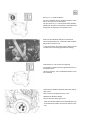
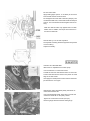
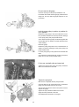
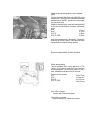
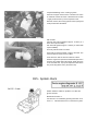
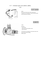
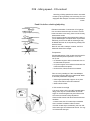
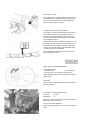
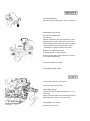
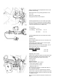
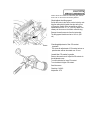
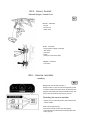
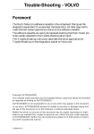
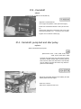
013 - Camshaft
adjust
(Carried out at 15,000 km and 90,000 km)
Adjust the camshaft belt
At an engine temperature of 40C (hand-hot engine)
Rotate the crankshaft clockwise to TDC (22 mm socket).
Remove the rubber plug in the timing gear cover. Undo
the tensioning pulley nut 1 - 1.5 turns (17 mm socket).
Tighten the nut. Refit the rubber plug.
014 - Camshaft, pump belt and idler pulley
replace
(Both camshaft and pump bell
Special tools: 999... 5187, 5188, 5190, 5193,
5194, 5197, 5199, 5201, 5202
I mportant! The engine may only be turned over manually with the vibration damper. When the timing belt has
been removed, neither the crankshaft nor the camshaft
may be rotated, otherwise the valves may strike the
piston and cause damage.
Disconnect the earth lead from the battery and the
splash-guard under the engine.
Drain the coolant
Remove the expansion tank cover.
Remove the alternator
Undo the servo pump with its bracket and let it hang
l oosely.
Automatic: Disconnect the oil cooling pipes from the
radiator
Remove:
- radiator fan and pulley
- radiator (D24 TIC: let the intercooler remain in position)
- drive belts
- valve cover
- timing belt covers front and rear
Remove:
- alternator belt
- fan shroud
- radiator fan with spacer and pulley
Remove:
- left hose from the intercooler
- A/C belt if fitted
- inlet manifold extension with EGR pipe
- crankcase ventilation hose from valve cover
Remove:
- valve cover
- upper (front) timing gear cover
- fuel pump belt cover
Set cyl. no. 1 at TDC injection
Turn the crankshaft with the vibration damper's centre
bolt 27 mm socket or tool 999 5188).
The two cams for cyl. 1 should point offset upwards,
parallel with the plane. The flywheel 0-marking should
be opposite the marking on the flywheel cover.
Remove the vibration damper's centre bolt
Use counterhold 999 5187, socket 999 5188 and drawbar handle to under the bolt.
I t may be necessary to turn the engine a little to get the
counterhold to fit securely against the fan bearing.
Check that cyl.1 is at TDC for injection
The flywheel 0-mark should be opposite the mark on
the flywheel cover.
Adjust if necessary, use counterhold 999 5187 to turn
the crankshaft.
Remove the vibration damper and lower timing
gear cover
Remove the four hexagonal screws, 6 mm.
Withdraw the vibration damper.
Remove the lower timing gear cover.
Note! The vibration damper and crankshaft gear may
sometimes stick together. Knock them apart if necessary.
Remove the camshaft belt
Undo the coolant pump's attachment screws and loosen the belt. Remove the belt.
Remove the idler pulley
The idler pulley should always be replaced when replacing the drive belt (timing gear belt)
Remove the centre bolt.
Pull out the idler pulley. Use pulley 999 5202.
Tap the new idler pulley into place. Ensure that it is
straight. Fit the centre bolt.
Remove camshaft belt
Undo the tension pulley nut and rotate the pulley as far
from the belt as possible, then lock the pulley in this
position.
Remove camshaft belt.
Check tension pulley: Rotate the pulley and listen for
abnormal sounds from the bearing. Check that the
pulley's surface facing the belt is clean and smooth.
When changing the tension pulley: Check carefully
that the spring is correctly positioned. Tension it with
the hexagon spanner and fix the pulley with the nut.
Check the idler pulley
Rotate the idler pulley and listen for noise from the
bearing. Check that the idler's surface against the belt
i s clean and smooth.
When changing the idler pulley: Remove the centre bolt
and pull out the idler pulley. Use pulley 999 5202.
Tap the new idler pulley into place, ensuring that it is
positioned correctly. Fit the centre bolt, torque 25 Nm.
Remove the fuel pump belt and rear camshaft
gear
Undo the pump bracket's attachment screws until the
belt is slackened. Tighten one screw so that the pump
remains in the upper position.
Remove the fuel pump belt.
Remove the camshaft gear. Use counterhold 999 5199
and socket 999 5201.
Note! Take care to ensure that the camshaft is not
rotated.
Remove the front camshaft pulley
Use counterhold 999 5199.
Tap the pulley so that it comes away from the camshaft
cone.
Lock the camshaft in the 0 position
Lift up the valve cover gasket.
I nsert gauge 999 5190 into the groove at the rear of the
camshaft. Place a feeler gauge, 0.2 mm, under the
i nstrument's left side.
The feeler gauge is used to compensate for tolerances
i n the timing gear.
Replace the 0-ring on the coolant pump
Remove the coolant pump.
Remove the splash guard and coolant pump's attachment screws.
Pull the guard away and remove the pump. Make sure
the guard does not crack.
Remove the 0-ring
Clean
Clean the contact surface between the pump and the
cylinder block. Wipe away all coolant from the cylinder
block, pulley etc.
Lubricate a new 0-ring with grease and fit it to
the pump
Do not use Permatex or any other sealing agent.
Apply a thin layer of grease to the pump's contact
surface.
Pull out the splash guard and fit the pump in place.
Loosely fit the pump's attachment screws.
Fit the splash guard screws.
Fit the camshaft belt and front camshaft pulley
Ensure that the belt is properly located on the teeth of
all the pulleys.
Tighten the front camshaft pulley's centre screw by
hand; it should be possible to rotate the shaft.
D 24 TIC (EGR): Undo the tension pulley nut so that it
moves freely.
Fit the lower timing gear cover and vibration
damper
The vibration damper only fits in one position. On the
crankshaft gear, there is a pin which is to fit into the
vibration damper.
Fit and tighten the hexagonal screws (6 mm) to 20 Nm
(2.0 kpm).
Fit the centre bolt
Apply sealing agent (P/N nr 11 61 056-5) to the centre
bolt's thread and the contact surface.
Fit and tighten the centre bolt to 350 Nm (35 kpm). Use
counterhold 999 5187, socket 999 5188 and torque
wrench. The counterhold should fit against the fan bearing.
Note! The 350 Nm value only applies when tool 999
5188 is used. In addition, the torque wrench must be in
li ne with tool 999 5188.
Check that cyl.1 is at TDC injection
The flywheel 0-marking should be opposite the flywheel
cover's marking.
Adjust if necessary.
Tension the camshaft belt
Belt tension is adjusted at the coolant pump.
Use tool 999 5197 to check belt tension.
Thread the tool over the belt and set it at 12.5 units.
Tension the belt until the mark on the piston is at the
edge of the tool socket.
Now apply firm hand pressure to the belt and check/adjust belt tension once again.
Tighten the front camshaft pulley and then remove fixture 999 5190
Use counterhold 999 5199. Take care to ensure that
neither the camshaft nor the pulley rotates.
Tighten the centre bolt to 45 Nm (4.5 kpm).
Remove gauge 999 5190 and the feeler gauge.
Tighten the front camshaft pulley and then remove fixture 999 5190
Use counterhold 999 5199. Take care to ensure that
neither the camshaft nor the pulley rotates.
Tighten the centre bolt to 100 Nm (10 kpm).
Remove gauge 999 5190 and the feeler gauge.
Tension the camshaft belt
Turn the crankshaft 2 revolutions clockwise, with loose
tension pulley. Lock the tension pulley without allowing
the crankshaft to stop, just before TDC is reached on
the second revolution.
Tighten the tension pulley nut to 15 Nm.
Check belt tension with tool 999 5197 between the
camshaft and idler pulley.
Belt tension should be between 12-13 units; if necessary, adjust with the help of the tension pulley.
Release the cold-start mechanism
Undo screw 1. Press the lever forwards and turn the
socket 90.
Note! Do not touch screw 2. If this screw is loosened,
the cold-start mechanism must be reset.
Press the lever backwards against the stop.
Basic installation of the injection pump
Undo the pump's attachment screws (the inner screw
i s a hexagonal 6 mm screw). Rotate the pump so that
the markings on the pump and the pump bracket match.
Tighten the attachment screws.
Fit and reset the dial gauge
Unscrew the plug from the pump's distributor unit.
Fit retainer 999 5194 and dial gauge (measurement
range min. 0-3 mm). Set the gauge at approx. 2 mm
pre-tension.
Lock the pump pulley in position in position for
cyl.1 injection
Rotate the pump pulley in the normal direction of rotation (clockwise viewed from the front) until the markings
on the pump pulley and pump bracket match.
Then rotate the pump pulley somewhat against the
normal direction of rotation until the dial shows the
l owest reading.
Reset the gauge.
Rotate the pump pulley back in the normal direction of
rotation so that the markings on the pump pulley and
pump bracket match.
Lock the pump pulley in this position with mandrel 999
5193.
(The mandrel is inserted through a hole in the pump
pulley into one of the pump bracket holes.)
Fit the rear camshaft pulley and pump belt
Tighten the centre bolt by hand, the pulley should be
able to be rotated at the camshaft.
Tighten the pump belt
Belt tension is adjusted with the pump brackets.
Use tool 999 5197 to check belt tension. Thread the
gauge over the belt and set it at 12.5 units.
Tension the belt until the mark on the piston is at the
edge of the gauge.
Tighten the pump bracket's attachment screws.
Apply firm hand pressure to the belt.
Check/adjust the belt tension once again.
Adjust the pump and tighten the rear camshaft
pulley
Position counterhold 999 5199, socket 999 5201 and a
torque wrench. The torque wrench should be positioned
perpendicular to 999 5201, otherwise the wrong tightening torque will result.
Rotate the camshaft pulley slowly with counterhold 999
5199 in the normal direction of rotation, until the dial
shows:
D24
0.70 m m
D 24 T
0.75 mm
D 24 TIC
0.90 mm
D 24 TIC (EGR)
0.95 mm
Keep the camshaft pulley in this position. Tighten the
centre bolt to 100 Nm (10 kpm). Take care that neither
the camshaft nor the pulley change position.
Remove mandrel 999 5193 from the pulley
Check pump setting
Turn the crankshaft until it is once again at cyl. 1 TDC
i njection. If the engine is turned too much, it must first
be returned approx. 114 revolution and then to the 0
mark, otherwise the adjustment will be incorrect.
The dial should now show:
D 24
0.65-0.73 mm
D 24 T
0.72-0.80 m m
D 24 TIC
0.87-0.95 mm
D 24 TIC (EGR)
0.92-1.00 mm
If the value is correct:
Continue with "Remove dial gauge
"
If the value is incorrect:
Adjust according to the following instructions.
Adjustment of pump setting:
Adjustment values:
D24
D 24 T
D 24 TIC
D 24 TIC (EGR)
0.70mm
0.75 mm
0.90 mm
0.95 mm
If the value is less than the adjustment value:
Undo the pump's attachment screws and turn the pump
i nwards to the adjustment value. Tighten the attachment screws and repeat the check of the pump setting.
If the value is greater than the adjustment value:
Undo the pump's attachment screws. Rotate the pump
first outwards until the gauge shows approx.
0.60mm
D24
0.65 m m
D 24 T
0.80 mm
D 24 TIC
0.85 mm
D 24 TIC (EGR)
Then rotate the pump inwards to the adjustment value.
Tighten the attachment screws and check the pump
adjustment once again.
I mportant! Under no circumstances whatsoever
should the pump be subjected to impacts or knocks
since this affects the unit and results in faulty adjustment.
Remove the dial gauge and retainer 999 5194.
Refit the plug with a new seal.
Torque 9 Nm (0.9 kpm).
Connect the cold-start unit
Press the lever forwards and turn the socket 90.
Tighten screw 1.
Note! Do not touch screw 2. If this screw is loosened,
the cold-start unit will have to be readjusted.
Fit the valve cover
Use new gaskets if necessary.
Fit the timing gear covers (front and rear)
Use new gaskets if necessary.
Fit:
- all the drive belts
- radiator fan with pulley
- inlet manifold extension with EGR pipe
- hoses to intercooler
Fit:
- the drive belts. Tension them until they can be pressed down 5-10 mm in the middle
- radiator (TIC: complete with intercooler)
- radiator fan with pulley
- automatic: Fit the oil cooler pipes from the radiator
- servo pump with bracket
- alternator
Prepare bleeding of the cooling system
Remove the upper hose from the cold-start unit. Place
a container under the hose. Hold the hose mouth
roughly level with the top of the expansion tank.
With this method, the cooling system is bled quickly and
all air pockets are eliminated.
Fill coolant
Volume: with manual gearbox approx. 11 litres (11.7
litres with tropical radiator)
with automatic gearbox approx. 10 litres (11.6 litres with
tropical radiator)
Use only Genuine Volvo coolant
Cars with CU: Set the heater control to full heat. The
function selector should not be on Max.
Cars with ACC: Set the function selector to OFF.
Start the engine and operate at raised idle speed for 5
minutes. Fill coolant during this period. Attach the hose
to the cold-start unit. Top up the expansion tank all the
way to the top (above max.) and fit the cap.
D15 - System check
1x 0,5 -1 sec
Attach selector cable to position 2 of the diagnosis socket.
Read test function 1:
Test function 1 is activated by pressing the button once.
Code 1.1.1 i ndicates that there is no fault in the system.
D16 - Exhaust gas recirculation (EGR)
check the function
Check the function
Check that the valve opens and shuts when the engine
speed rises.
Note! The valve opens only when the engine is warm
and engine speed exceeds idling speed.
Checking the EGR valve
- Ignition off
- Connect the yellow hose to the EGR valve
- Remove the yellow hose from the EGR converter
- Start the engine
- Pump up a vacuum (max. 30 kPa).
If vacuum drops:
- replace the EGR valve.
If the engine runs unevenly at idling speed:
- EGR valve OK.
If the engine runs smoothly at idling speed:
- Check that the EGR pipe is not blocked.
- Clean the pipe if necessary
- If the EGR pipe is OK, test with a new EGR valve.
The engine should run unevenly when the vacuum
pump shows negative pressure.
Three alternatives are possible as below:
1 The engine runs unevenly when the vacuum pump
shows negative pressure but the vacuum pump
l oses vacuum:
• Test with a new EGR valve.
2 The engine runs smoothly at idling speed when the
vacuum pump shows negative pressure and the
vacuum pump maintains vacuum:
• Check that the EGR pipe is not blocked. Clean if necessary. If the EGR pipe is OK, test with a new EGR
valve.
3 The engine runs unevenly at idling speed when the
vacuum pump shows negative pressure and the
vacuum pump maintains vacuum:
• the EGR system is OK.
D 1 7 - Exhaust gas recirculation (EGR)
clean
Clean
Remove and clean both the valve and the pipe.
Tap away any soot deposits; ensure that the valve and
pipe are clean before refitting.
Clean
Remove:
- the air hoses
- EGR valve with temperature sensor
- pipe connectors
Tap away any soot deposits; ensure that the valve and
pipe are clean before refitting.
Refit the parts.
D18 - Idling speed - CO-content
Checking of idling speed and carbon monoxide
content (CO) is generally not necessary for cars
equipped with catalytic converters and Lambdasonds.
Read this before checking/adjusting
Exhaust evacuation. Connection of CO gauge
Use an exhaust hose with open connector. If the exhaust evacuation is too strong, there is a risk of faulty
measurement results.
The CO gauge probe should penetrate about 480 mm
i nto the exhaust pipe. If the probe does not penetrate
sufficiently, there is a risk that the exhaust gas may
be diluted with fresh air, thus producing a faulty measurement result.
Note! On cars with a catalytic converter, the CO is
measured ahead of the catalyst.
Temperature
Checking/adjustment of CO-content should be performed at room temperature (between +15°C and
+25°C) and:
• on carburettor engines: within 3 minutes after the cool ant thermostat has opened
• on injection engines: at the earliest 5 minutes after the
coolant thermostat has opened.
• the electric fan, if fitted, should not have started.
Prior to every reading or if the check/adjustment has not been able to be performed within
3 minutes (carburettor engines)
• Raise engine speed briefly to approx. 25 r/s (1500
r/min) so that cold fuel enters the carburettor.
• Observe the time factor.
If CO-content is too high
I f the car is driven a lot in city traffic (repeated starts,
i dling), there may be a certain dilution of fuel with
engine oil. Crankcase gases may thus influence the
CO content and result in faulty adjustment.
Check the CO-content with disconnected crankcase
ventilation.
I n normal cases, the CO-content drops somewhat
when crankcase ventilation is disconnected.
I f the CO-content drops considerably, this is an indication that engine oil is diluted with the fuel. The engi ne oil should be changed.
The Pulsair system
The Pulsair system, if fitted, should be disconnected
and plugged for checking/adjustment of the CO-content. CO-content should not be checked/adjusted
with the Pulsair system connected.
F engines (with catalytic converter)
On catalytic converter equipped engines, the CO-content and idling speed do not normally need to be
checked. The new adaptive electronic control systems ensure that CO and idling values remain within
the specified tolerances.
Faulty values may be an indication of a fault in one of
the systems. Measurement of the CO-content is performed ahead of the catalytic converter by removing
a plug in the front exhaust pipe. On the B280F there
i s a plug for each row of cylinders.
The Lambdasond should always be disconnected
when a CO meter is used.
I dling speed, checking/adjustment
Correct idling speed:
cars without A/C:
14.2 r/s (850 r/m).
cars with A/C: 15.0 r/s (900 r/m) (A/C shut off).
Adjust the idling speed by turning the screw in the air
cleaner cover.
I mportant!
Check the float chamber ventilation after idling speed
has been adjusted.
CO-content, checking/adjustment
Checking:
0.5-2.5%
Adjustment:
1.5
Note: The electric radiator fan should not start during
adjustment of the CO-content.
Fit a new seal after adjustment.
Adjust idling speed after the CO-content has been adj usted.
Check/adjust automatic engine speed compensator
Check:
Disconnect the hoses (A) and (B) from the electric
three-way valve (1) and connect them together.
Note! do not disconnect any other connections.
Run the engine for about 10 seconds to stabilise the
engine speed.
Engine speed should now be 1375 -1425 r/m.
I f any other engine speed is registered, adjust as foll ows.
Adjustment:
Remove the rubber plug (2).
Adjust engine speed to 1400 r/m with adjustment
screw (3) on the vacuum unit.
Refit the rubber plug.
Connect the hoses to their respective connectors on
the three-way valve.
Pre-set idling speed
Hot engine. Correct idling speed: 15.0 r/s (900 r/min).
Check/adjust CO-content
Hot engine and idling speed.
Use tool 5015.
After each adjustment, the engine should be revved
briefly before the meter is read. Note! First remove
tool 5015 otherwise the meter lever may be damaged.
- Anti-clockwise turn (left) reduces CO-content
- Clockwise turn (right) increases CO-content
Sealing, CO adjustment screw
Legal requirement on certain markets.
Remove the plug with an awl or similar tool. Press in
a new plug after adjustment.
Connect the hose to Pulsair
Check/adjust idling speed
Pulsair system if fitted, is disconnected.
Connect the test socket to earth
Adjust idling speed
Use the idle screw to adjust idling speed to 11.7 r/s
(700 r/min).
Remove the earth cable from the test socket. Engine
speed should now rise to 12.5 r/s (750 r/min).
Check/adjust CO-content
Nominal value: 0.5-2.0%
For adjustment:
Remove the seal:
Engine switched off. Drill two holes in the plug. Drill
diameter 2 mm.
Withdraw the plug with circlip pliers. Start the engine.
Adjustment value: 1.0%
Rotate the adjustment screw
- anti-clockwise to reduce the CO-content
- clockwise to increase the CO-content
Seal the adjustment screw
Use a new plug. Tap it into place.
Switch off air conditioning.
Move the gear selector lever to N on cars with automatic gearbox.
Check idling speed and adjust the basic setting
(only B 18 EP)
Set the selector cable to position 2.
Start the engine.
Activate test function 2 by pressing the button twice,
0.5-1 secs. each time.
The LED will flash rapidly.
I dling speed should now be as follows:
B18EP
14.2 r/s (850 r/m)
Adjust if necessary with the adjustment screw on the
throttle valve housing.
Reset test function 2 by pressing the button once,
0.5-1 secs.
Remove the selector cable.
I dling speed should now be as above.
Checking/adjustment of CO-content (B 18 EP)
The CO-content is measured in the exhaust tailpipe
Should be adjusted with a hot engine and all current
consumers switched off (incl. radiator fan);
CO-content:
- for adjustment: 1 .2 -1.4
- for checking,
without EVAP:
1.0 -1.4
with EVAP:
0.8 - 3.0
Checking/adjustment of CO-content (B 18 UM,
B20EP)
Checking CO:
Move the gear selector lever to N on cars with an automatic gearbox.
Switch off the A/C and all current consumers apart
from the daylight running lamps.
Measure CO content in the exhaust tailpipe. The radiator fan should not be on during this test.
CO-content at i nspection:
B18U(M)
1.0-1.5%
B20F(M)
0.5-1.5%
Adjusting CO-content
Switch off the engine and wait for at least 20 seconds.
Remove the seal and connect tool 951 2019 to the
connectors (between the engine and monitor)
Start the engine.
Press button S.
Read the CO level.
Adjust CO with the + and - buttons
- CO too high: press the - button
- CO too low: press the + button
- Adjustment value 1.5
The CO level will continue to rise/fall after buttons +
and - have been pressed.
Press button S when the required level is reached.
Switch off the engine and wait for at least 20 seconds.
This gives the control unit time to enter the new value
i nto system memory.
Remove tool 951 2019 and seal the connectors once
again.
Switch off the air conditioner. Move the gear selector
lever to N on cars with an automatic gearbox.
Check/adjust the idling speed
Set the idle control valve to the nominal value by earthing the cable which is beside the valve at the front
of the engine. Switch off the air conditioner. Idling
speed should now be 11.7 r/s (700 r/m); adjust if necessary via the screw on the throttle valve housing.
Remove the earth connector from the test socket.
The idling speed should now rise to 14.2 r/s (850
r/m).
Checking/adjustment of the CO-content
Important!
The screw for adjustment of CO-content acts on a
potentiometer and can be rotated max. 15 revs.
Insert the CO-meter's probe.
Remove the screw's seal. Adjust the CO-content via
the adjustment screw.
Turn anti-clockwise for lower CO-content.
Turn clockwise for higher CO-content.
Seal the screw.
Checking: 0.4-0.8%
Adjustment: 0.7%
D19 - Doors, bonnet
l ubricate hinges, bonnet lock
Bonnet - lubricate
- hinges
- bonnet lock
- safety catch
Doors - lubricate
- hinges (does not apply to the 400)
- door stops
- lock lugs
- locks
- bearings on rear doors (850)
Tailgate - lubricate
- lock (480)
D20 - Service reminder
resetting
Diagnostic unit check function 4
Check function 4 in the control unit's diagnostic system
i s used to reset information which is stored for the
purpose of activating the service reminder lamp. This
service function shall be reset at every service.
Resetting the service reminder
Applies only to VDO instruments. With odometer bel ow the needle.
With Volvo Diagnostic Key
See service manual section 3(35-38) Lighting,
I nstrumentation and Other Electrical Equipment, 850
1992-, page 32.
Manually
I gnition on.
Select position 7 at diagnostic socket A.
Press 4 times, briefly but distinctly. You are now in
check function 4.
Press the first number (the key once) while the LED is
still glowing.
Do not press the second figure (press the key five
ti mes) until the LED glows steadily again.
Repeat the procedure for the third number (press the
key once).
Wait for a response from the control unit, whereby the
LED flashes rapidly a couple of times. Resetting is
complete and the service lamp is turned off.
D21 - Power antenna
clean
Clean the antenna as follows:
1. Raise the antenna
2. Spray the antenna rod with CRC 5-56 or
similar lubricant
3. Wipe the antenna dry
4. Spray the antenna rod once more
5. Raise and lower the antenna three times in
succession
6. Wipe the antenna dry