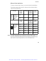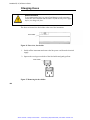
1
Lambda 25, 35, 45
User’s Guide
Artisan Scientific - Quality Instrumentation ... Guaranteed | (888) 88-SOURCE | www.artisan-scientific.com
Release History
Part Number
Release
Publication Date
09934422
A
August 2000
B
September 2000
User Assistance
PerkinElmer Ltd
Post Office Lane
Beaconsfield
Buckinghamshire
HP9 1QA
Printed in the United Kingdom.
Notices
The information contained in this document is subject to change without notice.
PerkinElmer makes no warranty of any kind with regard to the material, including, but not
limited to, the implied warranties of merchantability and fitness for a particular purpose.
PerkinElmer shall not be liable for errors contained herein for incidental consequential
damages in connection with furnishing, performance or use of this material.
Copyright Information
This document contains proprietary information that is protected by copyright.
All rights are reserved. No part of this publication may be reproduced in any form
whatsoever or translated into any language without the prior, written permission of
PerkinElmer, Inc.
Copyright © 2000 PerkinElmer, Inc.
Trademarks
Registered names, trademarks, etc. used in this document, even when not specifically marked
as such, are protected by law.
UV WinLab is a trademark of PerkinElmer, Inc.
PerkinElmer is a registered trademark of PerkinElmer, Inc.
Artisan Scientific - Quality Instrumentation ... Guaranteed | (888) 88-SOURCE | www.artisan-scientific.com
Contents
Contents
Contents .......................................................................................................... 3
Warnings and Safety Information .............................................................. 7
Safety Information.......................................................................................... 9
Safety Information in the Handbook ....................................................... 9
IEC 61010 Compliance ........................................................................... 9
CSA Compliance ..................................................................................... 9
Electrical Protection ................................................................................ 9
Electrical Safety..................................................................................... 10
EMC Compliance ......................................................................................... 13
EC Directive .......................................................................................... 13
FCC rules and regulations ..................................................................... 13
Environment ................................................................................................. 14
Lifting the Lambda 25, 35, 45 ...................................................................... 17
Labels............................................................................................................ 18
Introduction ................................................................................................ 21
About this Manual ........................................................................................ 23
Conventions Used in this Manual................................................................. 24
Definitions ............................................................................................. 24
Notes, cautions and warnings ................................................................ 24
Other Warnings used in this Manual ..................................................... 27
System Description ..................................................................................... 35
Introduction .................................................................................................. 37
Features ................................................................................................. 37
Optical System of the Lambda 25, 35, 45..................................................... 38
Lambda 25 Specification .............................................................................. 41
General .................................................................................................. 41
Optics..................................................................................................... 42
Abscissa................................................................................................. 42
Ordinate ................................................................................................. 43
Data Output ........................................................................................... 44
Lambda 35 Specification .............................................................................. 45
General .................................................................................................. 45
Optics..................................................................................................... 46
Abscissa................................................................................................. 46
Ordinate ................................................................................................. 47
3
Artisan Scientific - Quality Instrumentation ... Guaranteed | (888) 88-SOURCE | www.artisan-scientific.com
Lambda 25, 35, 45 User’s Guide
Lambda 45 Specification .............................................................................. 49
General .................................................................................................. 49
Optics..................................................................................................... 50
Abscissa................................................................................................. 50
Ordinate ................................................................................................. 51
Data Output ........................................................................................... 52
Installation................................................................................................... 53
Preparing the Working Area......................................................................... 55
Equipment Provided ..................................................................................... 57
Spectrometer.......................................................................................... 57
Components........................................................................................... 57
Unpacking your Instrument .......................................................................... 58
Unpacking and Inspection ..................................................................... 58
Connecting to the Electrical Supply ............................................................. 59
Setting up the PC .......................................................................................... 60
Connecting the PC to the spectrometer ................................................. 60
Installing UV WinLab ........................................................................... 60
Startup and Shutdown................................................................................... 61
Startup ................................................................................................... 61
Shutdown............................................................................................... 62
Installing the Single Cell Holder .................................................................. 63
Description ............................................................................................ 63
Accessories................................................................................................... 71
Accessory Installation................................................................................... 73
Accessory Connector Panel ................................................................... 74
Accessory Connections Overview......................................................... 76
Sample Compartment Cover ................................................................. 76
Sample Compartment Front Cover........................................................ 77
Sample Compartment Window ............................................................. 77
Linear Transporter ........................................................................................ 78
Installation Overview ............................................................................ 78
Temperature Sensor ...................................................................................... 79
Installation Overview ............................................................................ 79
Multisippers .................................................................................................. 80
Installation Overview ............................................................................ 80
Autosampler .......................................................................................... 81
Operating with Accessories .......................................................................... 82
General .................................................................................................. 82
4
Artisan Scientific - Quality Instrumentation ... Guaranteed | (888) 88-SOURCE | www.artisan-scientific.com
Contents
Accessories............................................................................................ 82
Requirements for Operation with Accessories ...................................... 83
Maintenance ................................................................................................ 85
Maintenance.................................................................................................. 87
Obtaining Service .................................................................................. 87
Daily Care.............................................................................................. 87
Cleaning the Sample Compartment....................................................... 88
Use and Care of Cells ................................................................................... 90
Cell Handling......................................................................................... 90
Pressure Buildup in Cells ...................................................................... 91
Replacing a Lamp ......................................................................................... 92
Halogen Lamp Replacement ................................................................. 93
Deuterium Lamp Replacement.............................................................. 96
Lamp Energy Attenuator ....................................................................... 99
Lamp Alignment Procedure................................................................. 101
Changing Fuses........................................................................................... 102
Replacement Parts ...................................................................................... 104
Analytical Notes ........................................................................................ 105
Unusual Samples ........................................................................................ 107
Volatile Samples.................................................................................. 107
Samples not Governed by the Beer-Lambert Law .............................. 107
Chemically Reactive Samples ............................................................. 108
Photoactive Samples............................................................................ 108
Other Sample Properties...................................................................... 108
Solvent Properties....................................................................................... 109
Index .......................................................................................................... 111
Index ........................................................................................................... 113
5
Artisan Scientific - Quality Instrumentation ... Guaranteed | (888) 88-SOURCE | www.artisan-scientific.com
Lambda 25, 35, 45 User’s Guide
6
Artisan Scientific - Quality Instrumentation ... Guaranteed | (888) 88-SOURCE | www.artisan-scientific.com
Warnings and
Safety Information
1
Artisan Scientific - Quality Instrumentation ... Guaranteed | (888) 88-SOURCE | www.artisan-scientific.com
Artisan Scientific - Quality Instrumentation ... Guaranteed | (888) 88-SOURCE | www.artisan-scientific.com
Warnings and Safety Information
Safety Information
Safety Information in the Handbook
This handbook contains information and warnings that must be followed by the user
to ensure safe operation and to maintain the instrument in a safe condition.
Possible hazards that could harm the user or result in damage to the instrument are
clearly stated at appropriate places throughout this handbook.
Before using the instrument it is essential to read the manual carefully and to pay
particular attention to any advice concerning potential hazards that may arise from
the use of the instrument. The advice is intended to supplement, not supercede the
normal safety code of behavior prevailing in the user’s country.
IEC 61010 Compliance
This instrument has been designed and tested in accordance with IEC 1010-1: Safety
requirements for electrical equipment for measurement, control, and laboratory use,
and Amendment 1 to this standard.
CSA Compliance
This instrument meets the Canadian Standards Association (CSA) Standard
CAN/CSA-C22.2-1010.1: Safety Requirements for Electrical Equipment for
Measurement, Control, and Laboratory Use – General Requirements.
Electrical Protection
Insulation: Class I as defined in IEC 61010-1.
Installation Category: The instruments are able to withstand transient overvoltage
according to Installation Category II as defined in IEC 61010-1 and IEC 664.
9
Artisan Scientific - Quality Instrumentation ... Guaranteed | (888) 88-SOURCE | www.artisan-scientific.com
Lambda 25, 35, 45 User’s Guide
Pollution Degree: The equipment will operate safely in environments that contain
non-conductive foreign matter and condensation up to Pollution Degree 2 - usually
only non-conductive atmospheric pollution of the equipment occurs; occasionally,
however, a temporary conductivity caused by condensation must be expected.
Electrical Safety
To ensure satisfactory and safe operation of the instrument, it is essential that the
green/yellow lead of the line power cord is connected to true electrical earth
(ground).
If any part of the instrument is not installed by a PerkinElmer service representative,
make sure that the line power plug is wired correctly:
Cord Lead Colors
Terminal
International
USA
Live
Brown
Black
Neutral
Blue
White
Protective Conductor
(earth/ground)
Green/Yellow
Green
10
Artisan Scientific - Quality Instrumentation ... Guaranteed | (888) 88-SOURCE | www.artisan-scientific.com
Warnings and Safety Information
WARNING
Electrical Hazard
Any interruption of the protective conductor inside or outside the
instrument or disconnection of the protective conductor (earth/ground)
terminal is likely to make the instrument dangerous.
Intentional interruption is prohibited.
Lethal voltages are present in the instrument
•
Even with the power switch OFF, line power voltages can still be
present within the instrument.
•
When the instrument is connected to line power, terminals may be
live, and opening covers or removing parts (except those to which
access can be gained without the use of a tool) is likely to expose
live parts.
•
Capacitors inside the instrument may still be charged even if the
instrument has been disconnected from all voltage sources.
Connect the instrument to a correctly installed line power outlet that has a protective
conductor (earth/ground).
Do not attempt to make internal adjustments or replacements except as directed in
this handbook.
Do not operate the instrument with any covers or parts removed.
Servicing should be carried out only by a PerkinElmer service representative or
similarly authorized and trained person.
Disconnect the instrument from all voltage sources before opening it for any
adjustment, replacement, maintenance, or repair. If, afterwards, the opened
instrument must be operated for further adjustment, maintenance, or repair, this must
only be done by a skilled person who is aware of the hazard involved.
11
Artisan Scientific - Quality Instrumentation ... Guaranteed | (888) 88-SOURCE | www.artisan-scientific.com
Lambda 25, 35, 45 User’s Guide
Use only fuses with the required current rating and of the specified type for
replacement. Do not use makeshift fuses or short-circuit the fuse holders.
Whenever it is likely that the instrument is no longer electrically safe for use, make
the instrument inoperative and secure it against any unauthorized or unintentional
operation.
The instrument is likely to be electrically unsafe when it:
•
Shows visible damage;
•
Fails to perform the intended measurement;
•
Has been subjected to prolonged storage under unfavorable conditions;
•
Has been subjected to severe transport stresses.
If the equipment is used in a manner not specified herein the protection
provided by the equipment may be impaired.
WARNING
12
Artisan Scientific - Quality Instrumentation ... Guaranteed | (888) 88-SOURCE | www.artisan-scientific.com
Warnings and Safety Information
EMC Compliance
EC Directive
This product complies with the minimum immunity requirements of IEC 61326 and
has been tested to the relevant parts of the following standards:
IEC 61000-4-2
IEC 61000-4-3
IEC 61000-4-4
IEC 61000-4-5
IEC 61000-4-6
IEC 61000-4-11
This product complies with EN 55011 Group 1 Class A and IEC 61000-3-2.
FCC rules and regulations
This product is classified as a digital device used exclusively as industrial,
commercial, or medical test equipment. It is exempt from the technical standards
specified in Part 15 of the FCC Rules and Regulations, based on Section 15.103(c).
13
Artisan Scientific - Quality Instrumentation ... Guaranteed | (888) 88-SOURCE | www.artisan-scientific.com
Lambda 25, 35, 45 User’s Guide
Environment
Operating Conditions
Explosive Atmosphere
WARNING
This instrument is not designed for operation in an explosive
atmosphere.
The instrument will operate correctly under the following conditions:
•
Indoors.
•
Ambient temperature +15 ºC to +35 ºC.
•
Ambient relative humidity 20% to 80%, without condensation.
•
Altitude in the range 0 m to 2000 m.
The instrument has been designed to be safe under the following environmental
conditions:
•
Indoor use.
•
Ambient temperatures of 5 ºC to 40 ºC.
•
A maximum ambient relative humidity of 80% for temperatures up to
31 oC, decreasing linearly to 50% relative humidity at 40 oC.
•
Altitude up to 2000 m (above mean sea level).
•
Mains supply fluctuations not exceeding ± 10% of the nominal voltage.
14
Artisan Scientific - Quality Instrumentation ... Guaranteed | (888) 88-SOURCE | www.artisan-scientific.com
Warnings and Safety Information
When you remove the instrument from storage, before putting it into operation allow
it to stand for at least a day under the approved operating conditions.
Chemicals
Use, store, and dispose of chemicals that you require for your analyses in
accordance with the manufacturer’s recommendations and local safety regulations.
Hazardous Chemicals
Some chemicals used with this instrument may be hazardous or may
become hazardous after completion of an analysis.
WARNING
The responsible body (for example, Laboratory Manager) must take
the necessary precautions to ensure that the surrounding workplace
and instrument operators are not exposed to hazardous levels of toxic
substances (chemical or biological) as defined in the applicable
Material Safety Data Sheets (MSDS) or OSHA, ACGIH, or COSHH
documents.
Venting for fumes and disposal of waste must be in accordance with all
national, state and local health and safety regulations and laws.
OSHA: Occupational Safety and Health Administration (U.S.A.)
ACGIH: American Conference of Governmental Industrial Hygienists (U.S.A)
COSHH: Control of Substances Hazardous to Health (U.K.)
Toxic Fumes
If you are working with volatile solvents or toxic substances, you must provide an
efficient laboratory ventilation system to remove vapors that may be produced when
you are performing analyses.
15
Artisan Scientific - Quality Instrumentation ... Guaranteed | (888) 88-SOURCE | www.artisan-scientific.com
Lambda 25, 35, 45 User’s Guide
Waste Disposal
Waste containers may contain corrosive or organic solutions and small amounts of
the substances that were analyzed. If these materials are toxic, you may have to treat
the collected effluent as hazardous waste. Refer to your local safety regulations for
proper disposal procedures.
Deuterium lamps and other spectral lamps are maintained under reduced pressure.
When you dispose of lamps that are defective or otherwise unusable, handle them
correctly to minimize the implosion risk.
UV Radiation
You should be aware of the health hazards presented by ultraviolet radiation.
•
When the deuterium (UV) lamp is illuminated, do not open the
spectrophotometer covers unless specifically instructed to do so in the manual.
•
Always wear UV-absorbing eye protection when the deuterium lamp is
exposed.
•
Never gaze into the deuterium lamp.
16
Artisan Scientific - Quality Instrumentation ... Guaranteed | (888) 88-SOURCE | www.artisan-scientific.com
Warnings and Safety Information
Lifting the Lambda 25, 35, 45
Consult local codes or practice issued by safety advisors before
attempting to lift the instrument.
WARNING
As the Lambda 25, 35, 45 weighs approximately 26 Kg we recommend that the
instrument is lifted by 2 adults, and that it is lifted by the base of the instrument.
17
Artisan Scientific - Quality Instrumentation ... Guaranteed | (888) 88-SOURCE | www.artisan-scientific.com
Lambda 25, 35, 45 User’s Guide
Labels
Labels are fixed to the Lambda 25, 35, 45 in the locations shown in Figure 1 and
Figure 3.
Serial number
Electrical warnings
Serial number inside the
sample compartment
Figure 1 Labels on the spectrometer housing
The following electrical warnings are shown on the rear of the instrument:
Figure 2 Warning labels on the rear of the instrument
18
Artisan Scientific - Quality Instrumentation ... Guaranteed | (888) 88-SOURCE | www.artisan-scientific.com
Warnings and Safety Information
Warning labels shown on the
inside of the lamp compartment
Figure 3 Lambda 25, 35, 45 Spectrometers warning labels (inside of lamp
compartment)
The following warnings are shown on the inside of the lamp compartment.
Figure 4 Warnings on the inside of the lamp compartment
19
Artisan Scientific - Quality Instrumentation ... Guaranteed | (888) 88-SOURCE | www.artisan-scientific.com
Lambda 25, 35, 45 User’s Guide
20
Artisan Scientific - Quality Instrumentation ... Guaranteed | (888) 88-SOURCE | www.artisan-scientific.com
Introduction
2
Artisan Scientific - Quality Instrumentation ... Guaranteed | (888) 88-SOURCE | www.artisan-scientific.com
Artisan Scientific - Quality Instrumentation ... Guaranteed | (888) 88-SOURCE | www.artisan-scientific.com
Introduction
About this Manual
This manual contains the following sections:
•
Warnings and Safety Information;
•
Introduction;
•
System Description;
•
Installation;
•
Accessories;
•
Maintenance;
•
Analytical Notes.
23
Artisan Scientific - Quality Instrumentation ... Guaranteed | (888) 88-SOURCE | www.artisan-scientific.com
Lambda 25, 35, 45 User’s Guide
Conventions Used in this Manual
Normal text is used to provide information and instructions.
Bold text refers to text that is displayed on the screen.
UPPERCASE text, for example ENTER or ALT, refers to keys on the PC keyboard.
‘+’ is used to show that you have to press two keys at the same time, for example,
ALT + F.
Definitions
Responsible body: individual or group responsible for the use and maintenance of
equipment, and for ensuring that operators are adequately trained.
Operator: person operating equipment for its intended purpose.
Notes, cautions and warnings
Three terms in the following standard formats, are also used to highlight special
circumstances and warnings.
NOTE: A note indicates additional, significant information that is provided with some
procedures.
24
Artisan Scientific - Quality Instrumentation ... Guaranteed | (888) 88-SOURCE | www.artisan-scientific.com
Introduction
CAUTION
D
DK
We use the term CAUTION to inform you about situations that could
result in serious damage to the instrument or other equipment. Details
about these circumstances are in a box like this one.
Caution (Achtung)
Bedeutet, daß die genannte Anleitung genau befolgt werden muß, um
einen Geräteschaden zu vermeiden.
Caution (Bemærk)
Dette betyder, at den nævnte vejledning skal overholdes nøje for at
undgå en beskadigelse af apparatet.
E
Caution (Advertencia)
Utilizamos el término CAUTION (ADVERTENCIA) para advertir sobre
situaciones que pueden provocar averías graves en este equipo o en
otros. En recuadros éste se proporciona información sobre este tipo de
circunstancias.
F
Caution (Attention)
Nous utilisons le terme CAUTION (ATTENTION) pour signaler les
situations susceptibles de provoquer de graves détériorations de
l'instrument ou d'autre matériel. Les détails sur ces circonstances
figurent dans un encadré semblable à celui-ci.
I
Caution (Attenzione)
Con il termine CAUTION (ATTENZIONE) vengono segnalate situazioni
che potrebbero arrecare gravi danni allo strumento o ad altra
apparecchiatura. Troverete informazioni su tali circostanze in un
riquadro come questo.
NL
P
Caution (Opgelet)
Betekent dat de genoemde handleiding nauwkeurig moet worden
opgevolgd, om beschadiging van het instrument te voorkomen.
Caution (Atenção)
Significa que a instrução referida tem de ser respeitada para evitar a
danificação do aparelho.
25
Artisan Scientific - Quality Instrumentation ... Guaranteed | (888) 88-SOURCE | www.artisan-scientific.com
Lambda 25, 35, 45 User’s Guide
We use the term WARNING to inform you about situations that could
result in personal injury to yourself or other persons. Details about
these circumstances are in a box like this one.
WARNING
D
DK
Warning (Warnung)
Bedeutet, daß es bei Nichtbeachten der genannten Anweisung zu einer
Verletzung des Benutzers kommen kann.
Warning (Advarsel)
Betyder, at brugeren kan blive kvæstet, hvis anvisningen ikke
overholdes.
E
Warning (Peligro)
Utilizamos el término WARNING (PELIGRO) para informarle sobre
situaciones que pueden provocar daños personales a usted o a otras
personas. En los recuadros como éste se proporciona información sobre
este tipo de circunstancias.
F
Warning (Danger)
Nous utilisons la formule WARNING (DANGER) pour avertir des
situations pouvant occasionner des dommages corporels à l'utilisateur
ou à d'autres personnes. Les détails sur ces circonstances sont données
dans un encadré semblable à celui-ci.
I
Warning (Pericolo)
Con il termine WARNING (PERICOLO) vengono segnalate situazioni
che potrebbero provocare incidenti alle persone. Troverete informazioni
su tali circostanze in un riquadro come questo.
NL
P
Warning (Waarschuwing)
Betekent dat, wanneer de genoemde aanwijzing niet in acht wordt
genomen, dit kan leiden tot verwondingen van de gebruiker.
Warning (Aviso)
Significa que a não observância da instrução referida poderá causar um
ferimento ao usuário.
26
Artisan Scientific - Quality Instrumentation ... Guaranteed | (888) 88-SOURCE | www.artisan-scientific.com
Introduction
Other Warnings used in this Manual
27
Artisan Scientific - Quality Instrumentation ... Guaranteed | (888) 88-SOURCE | www.artisan-scientific.com
Lambda 25, 35, 45 User’s Guide
28
Artisan Scientific - Quality Instrumentation ... Guaranteed | (888) 88-SOURCE | www.artisan-scientific.com
Introduction
29
Artisan Scientific - Quality Instrumentation ... Guaranteed | (888) 88-SOURCE | www.artisan-scientific.com
Lambda 25, 35, 45 User’s Guide
30
Artisan Scientific - Quality Instrumentation ... Guaranteed | (888) 88-SOURCE | www.artisan-scientific.com
Introduction
31
Artisan Scientific - Quality Instrumentation ... Guaranteed | (888) 88-SOURCE | www.artisan-scientific.com
Lambda 25, 35, 45 User’s Guide
32
Artisan Scientific - Quality Instrumentation ... Guaranteed | (888) 88-SOURCE | www.artisan-scientific.com
Introduction
33
Artisan Scientific - Quality Instrumentation ... Guaranteed | (888) 88-SOURCE | www.artisan-scientific.com
Lambda 25, 35, 45 User’s Guide
34
Artisan Scientific - Quality Instrumentation ... Guaranteed | (888) 88-SOURCE | www.artisan-scientific.com
System Description
3
Artisan Scientific - Quality Instrumentation ... Guaranteed | (888) 88-SOURCE | www.artisan-scientific.com
Artisan Scientific - Quality Instrumentation ... Guaranteed | (888) 88-SOURCE | www.artisan-scientific.com
System Description
Introduction
The Lambda 25, 35, 45 are versatile spectrometers operating in the ultraviolet (UV)
and visible (Vis) spectral ranges. The spectrometers feature a double-beam, allreflecting system.
Lambda 25, 35, 45 spectrometers are usable in a wide range of applications as
indicated by their performance specification.
Features
Lamp compartment
Power switch
Sample compartment
Connector panel
Figure 5 Lambda 25, 35, 45 Spectrometer Features
37
Artisan Scientific - Quality Instrumentation ... Guaranteed | (888) 88-SOURCE | www.artisan-scientific.com
Lambda 25, 35, 45 User’s Guide
Optical System of the Lambda 25, 35, 45
The Lambda 25, 35, 45 UV/Vis Spectrometers features an all-reflecting optical
system. The optical components are coated with silica for durability. A holographic
grating is used in the monochromator.
The optical system is depicted schematically in Figure 6.
The monochromator is a holographic concave grating with 1053 lines/mm in
the center.
Two radiation sources, a deuterium lamp and a halogen lamp, cover the working
wavelength range of the spectrometer.
For operation in the visible (Vis) range, mirror M1 reflects the radiation from the
halogen lamp onto source mirror M2. At the same time M1 blocks the radiation
from the deuterium lamp.
NOTE: In the Lambda 45, M2 is substituted by a pre-monochromator grating, increasing
the straylight performance of the instrument.
For operation in the ultraviolet (UV) range, mirror M1 is raised to permit radiation
from the deuterium lamp to strike source mirror M2.
Source change is automatic during monochromator slewing.
Radiation from the source lamp is reflected from source mirror M2 through an
optical filter on the filter wheel assembly.
A stepping motor drives the filter wheel to be in sychronization with the
monochromator.
Depending on the wavelength being produced, the appropriate optical filter is
located in the beam path to prefilter the radiation before it enters the
monochromator.
Filter change is automatic during monochromator slewing.
38
Artisan Scientific - Quality Instrumentation ... Guaranteed | (888) 88-SOURCE | www.artisan-scientific.com
System Description
From the optical filter the radiation passes through the entrance slit (Slit 1) of the
monochromator.
The radiation is dispersed at the grating to produce a spectrum. The rotational
position of the grating effectively selects a segment of the spectrum, reflecting this
segment through the exit slit (Slit 2) to mirror M3.
Halogen
lamp
M = Mirror
M1, M4, and M5 = Plane Mirror
M2 = Toroidal Mirror
M3 = Spherical Mirror
M2*
Deuterium
lamp
M1
Filter wheel
Reference
Slit 1
†
M5
Slit 2
M3
†
Detector
Lens
Beam Splitter
Lens
Grating
(Monochromator)
M4
Sample
Detector
Figure 6 Optical Path for Lambda 25, 35, 45
* replaced
†
with a pre-monochromator in the Lambda 45
- selectable on the Lambda 35/45
39
Artisan Scientific - Quality Instrumentation ... Guaranteed | (888) 88-SOURCE | www.artisan-scientific.com
Lambda 25, 35, 45 User’s Guide
The exit slit restricts the spectrum segment to a near-monochromatic radiation beam.
The slits provide a spectral bandpass of 1 nm on the Lambda 25, and are selectable
to be 0.5, 1, 2, or 4 nm on the Lambda 35 or 45.
From mirror M3 the radiation is reflected onto a beam splitter which allows 50% of
the radiation to pass onto plane mirror M4, and reflects 50% of the radiation onto
plane mirror M5.
Mirror M4 focuses the radiation beam in the sample cell.
The beam then passes through a convex lens onto the photodiode detector.
Mirror M5 focuses the radiation beam in the reference cell.
The beam then passes through a convex lens onto the photodiode detector.
40
Artisan Scientific - Quality Instrumentation ... Guaranteed | (888) 88-SOURCE | www.artisan-scientific.com
System Description
Lambda 25 Specification
General
Type
Scanning double-beam spectrometer for the
UV/Vis range; operation by PC
Dimensions
Width: 650 nm
Height: 260 nm
Depth: 560 nm
Mass
26 kg approx.
Power requirements
100 V to 240 V AC, 50/60 Hz; 250 VA
Ambient operating temperature
15 ºC to 35 ºC
Humidity range
20% to 80% relative humidity without
condensation
Technical Standard
In compliance with the requirements for
technical instruments stipulated by
IEC 61010-1:1990 and amendments
A1:1992 and A2:1995.
Radio interference suppression
In compliance with the legal requirements
of the EMC directive 89.336/EEC
(EN 61326)
41
Artisan Scientific - Quality Instrumentation ... Guaranteed | (888) 88-SOURCE | www.artisan-scientific.com
Lambda 25, 35, 45 User’s Guide
Optics
Beam center height
15 mm above cell holder bottom
Beam cross-section
1 nm slit ca. 0.6 mm x 9 mm (width x height)
at focal point of sample and reference beam in
sample compartment
Optical pathlength in
sample compartment
121 mm
Grating (Monochromator)
Holographic concave grating with 1053 lines/mm
in the center
Radiation sources
Prealigned deuterium and halogen lamps
Detector
Photodiodes
(One for the sample beam and one for the
reference beam)
Abscissa
Wavelength range
190 nm to 1100 nm;
0 nm for alignment purposes
Wavelength accuracy
±0.1 nm
Wavelength reproducibility
±0.1 nm
Spectral bandwidth
1 nm (fixed slit)
Lamp change
Automatically at 326 nm
(software selectable over the whole
wavelength range)
Scan speeds
7.5, 15, 30 , 60, 120, 240, 480, 960,
1920 and 2880 nm/min
42
Artisan Scientific - Quality Instrumentation ... Guaranteed | (888) 88-SOURCE | www.artisan-scientific.com
System Description
Ordinate
Photometric range
Transmission 0% to 100%
Absorbance –6.000 to 6.000 (display range)
1 to 9999 (concentration units)
Photometric accuracy
Absorbance ±0.003
(measured at Absorbance = 1 at 440 nm, 546.1 nm and
635 nm with NIST 930 filters)
Absorbance ±0.015
(measured at Absorbance = 1, at 257 nm and 350 nm
with potassium dichromate solution*)
Stray radiation
Transmission < 0.02%
(at 220 nm, 340 nm and 370 nm)
Absorbance > 2
(measured at 200 nm with potassium chloride solution†
against distilled water)
Baseline linearity
1 nm slit:
Absorbance ±0.001
(corrected: 200 nm to 1100 nm, scan speed 240
nm/min, smooth 2)
Baseline noise
1 nm slit:
Absorbance < 0.00008 RMS,
Absorbance < 0.0003 peak-to-peak
3 min at absorbance = 0, wavelength 500 nm and
response 2 s)
Baseline stability
(drift)
*
†
Absorbance < 0.0003 per hour
(500 nm, after warmup)
β(K2Cr2O7) = 60.06 µg/mL ±0.5% in sulfuric acid c(H2SO4) = 0.005 mol/L
β(KC1)= 12 mg/mL ±0.5%
43
Artisan Scientific - Quality Instrumentation ... Guaranteed | (888) 88-SOURCE | www.artisan-scientific.com
Lambda 25, 35, 45 User’s Guide
Data Output
Digital port
One RS 232 C interface (serial), for connecting a PC.
44
Artisan Scientific - Quality Instrumentation ... Guaranteed | (888) 88-SOURCE | www.artisan-scientific.com
System Description
Lambda 35 Specification
General
Type
Scanning double-beam spectrometer for the
UV/Vis range; operation by PC
Dimensions
Width: 650 nm
Height: 260 nm
Depth: 560 nm
Mass
26 kg approx.
Power requirements
100 V to 240 V AC, 50/60 Hz; 250 VA
Ambient operating temperature
15 ºC to 35 ºC
Humidity range
20% to 80% relative humidity without
condensation
Technical Standard
In compliance with the requirements for
technical instruments stipulated by
IEC 61010-1:1990 and amendments
A1:1992 and A2:1995.
Radio interference suppression
In compliance with the legal requirements
of the EMC directive 89.336/EEC
(EN 61326)
45
Artisan Scientific - Quality Instrumentation ... Guaranteed | (888) 88-SOURCE | www.artisan-scientific.com
Lambda 25, 35, 45 User’s Guide
Optics
Beam center height
15 mm above cell holder bottom
Beam cross-section
0.5 nm slit
ca. 0.25 mm x 7 mm (width x height)
1 nm slit
ca. 0.5 mm x 7.5 mm (width x height)
2 nm slit
ca. 1 mm x 7.5 mm (width x height)
4 nm slit
ca 2 mm x 7.5 mm (width x height),
at focal point of sample and reference beam in sample
compartment
Optical pathlength in
sample compartment
121 mm
Grating
(Monochromator)
Holographic concave grating with 1053 lines/mm in the
center
Radiation sources
Prealigned deuterium and halogen lamps
Detector
Photodiodes
(One for the sample beam and one for the reference beam)
Abscissa
Wavelength range
190 nm to 1100 nm; 0 nm for alignment purposes
Wavelength accuracy
±0.1 nm
Wavelength reproducibility
±0.1 nm
Spectral bandwidth
0.5 nm, 1 nm, 2 nm, 4 nm
(selectable fixed slit widths)
Lamp change
Automatically at 326 nm
(software selectable over the whole wavelength range)
Scan speeds
7.5, 15, 30 , 60, 120, 240, 480, 960, 1920 and 2880
nm/min
46
Artisan Scientific - Quality Instrumentation ... Guaranteed | (888) 88-SOURCE | www.artisan-scientific.com
System Description
Ordinate
Photometric range
Transmission 0% to 100%
Absorbance –6.000 to 6.000 (display range)
1 to 9999 (concentration units)
Photometric accuracy
Absorbance ±0.003
(measured at Absorbance = 1 at 440 nm, 546.1 nm and
635 nm with NIST 930 filters)
Absorbance ±0.015
(measured at Absorbance = 1, at 257 nm and 350 nm
with potassium dichromate solution*)
Stray radiation
Transmission < 0.02%
(at 220 nm, 340 nm and 370 nm)
Absorbance > 2
(measured at 200 nm with potassium chloride† solution
against distilled water)
Baseline linearity
2 nm slit:
Absorbance ±0.0005
(corrected: 200 nm to 1050 nm, scan speed 240
nm/min, smooth 2)
Baseline noise
2 nm slit:
Absorbance < 0.00006 RMS,
Absorbance < 0.0002 peak-to-peak
3 min at Absorbance = 0, wavelength 500 nm and
response 2 s)
Baseline stability
(drift)
*
†
Absorbance < 0.0003 per hour
(500 nm, after warmup)
β(K2Cr2O7) = 60.06 µg/mL ±0.5% in sulfuric acid c(H2SO4) = 0.005 mol/L
β(KC1)= 12 mg/mL ±0.5%
47
Artisan Scientific - Quality Instrumentation ... Guaranteed | (888) 88-SOURCE | www.artisan-scientific.com
Lambda 25, 35, 45 User’s Guide
Data Output
Digital port
One RS 232 C interface (serial), for connecting a PC
48
Artisan Scientific - Quality Instrumentation ... Guaranteed | (888) 88-SOURCE | www.artisan-scientific.com
System Description
Lambda 45 Specification
General
Type
Scanning double-beam spectrometer for the
UV/Vis range; operation by PC
Dimensions
Width: 650 nm
Height: 260 nm
Depth: 560 nm
Mass
26 kg approx.
Power requirements
100 V to 240 V AC, 50/60 Hz; 250 VA
Ambient operating temperature
15 ºC to 35 ºC
Humidity range
20% to 80% relative humidity without
condensation
Technical Standard
In compliance with the requirements for
technical instruments stipulated by
IEC 61010-1:1990 and amendments
A1:1992 and A2:1995.
Radio interference suppression
In compliance with the legal requirements
of the EMC directive 89.336/EEC
(EN 61326)
49
Artisan Scientific - Quality Instrumentation ... Guaranteed | (888) 88-SOURCE | www.artisan-scientific.com
Lambda 25, 35, 45 User’s Guide
Optics
Beam center height
15 mm above cell holder bottom
Beam cross-section
0.5 nm slit
ca. 0.25 mm x 7 mm (width x height)
1 nm slit
ca. 0.5 mm x 7.5 mm (width x height)
2 nm slit
ca. 1 mm x 7.5 mm (width x height)
4 nm slit
ca 2 mm x 7.5 mm (width x height),
at focal point of sample and reference beam in sample
compartment
Optical pathlength in
sample compartment
121 mm
Grating
(Monochromator)
Holographic concave grating with 1053 lines/mm in the
center
Radiation sources
Prealigned deuterium and halogen lamps
Detector
Photodiodes
(One for the sample beam and one for the reference beam)
Abscissa
Wavelength range
190 nm to 1100 nm; 0 nm for alignment purposes
Wavelength accuracy
±0.1 nm
Wavelength reproducibility
±0.1 nm
Spectral bandwidth
0.5 nm, 1 nm, 2 nm, 4 nm
(selectable fixed slit widths)
Lamp change
Automatically at 326 nm
(software selectable over the whole wavelength range)
Scan speeds
7.5, 15, 30 , 60, 120, 240, 480, 960, 1920 and 2880
nm/min
50
Artisan Scientific - Quality Instrumentation ... Guaranteed | (888) 88-SOURCE | www.artisan-scientific.com
System Description
Ordinate
Photometric range
Transmission 0% to 100%
Absorbance –6.000 to 6.000 (display range)
1 to 9999 (concentration units)
Photometric accuracy
Absorbance ±0.003
(measured at Absorbance = 1 at 440 nm, 546.1 nm and
635 nm with NIST 930 filters)
Absorbance ±0.015
(measured at Absorbance = 1, at 257 nm and 350 nm
with potassium dichromate solution*)
Stray radiation
Transmission < 0.02%
(at 220 nm, 340 nm and 370 nm)
Absorbance > 2
(measured at 200 nm with potassium chloride† solution
against distilled water)
Baseline linearity
2 nm slit:
Absorbance ±0.0005
(corrected: 200 nm to 1100 nm, scan speed
240 nm/min, smooth 2)
Baseline noise
2 nm slit:
Absorbance < 0.00006 RMS,
Absorbance < 0.0002 peak-to-peak
3 min at Absorbance = 0, wavelength 500 nm and
response 2 s)
Baseline stability
(drift)
*
†
Absorbance < 0.0003 per hour
(500 nm, after warmup)
β(K2Cr2O7) = 60.06 µg/mL ±0.5% in sulfuric acid c(H2SO4) = 0.005 mol/L
β(KC1)= 12 mg/mL ±0.5%
51
Artisan Scientific - Quality Instrumentation ... Guaranteed | (888) 88-SOURCE | www.artisan-scientific.com
Lambda 25, 35, 45 User’s Guide
Data Output
Digital port
One RS 232 C interface (serial), for connecting a PC
52
Artisan Scientific - Quality Instrumentation ... Guaranteed | (888) 88-SOURCE | www.artisan-scientific.com
Installation
4
Artisan Scientific - Quality Instrumentation ... Guaranteed | (888) 88-SOURCE | www.artisan-scientific.com
Artisan Scientific - Quality Instrumentation ... Guaranteed | (888) 88-SOURCE | www.artisan-scientific.com
Installation
Preparing the Working Area
For maximum stability and minimum maintenance observe the following
requirements when siting the instrument:
•
A firm base free from vibration.
•
Enough space around and underneath the instrument for efficient air
circulation.
•
A constant temperature between 15 ºC and 35 ºC.
•
Constant humidity between 20% and 80% relative humidity.
•
An atmosphere free from dust and corrosive fumes.
•
Keep out of direct sunlight.
Illumination with diffuse lighting is ideal.
•
A suitable source of electrical power should be located in the vicinity of the
instrument.
Electrical power must be available at a proper earth-grounded 3-wire electrical
outlet.
•
The standard sample compartment baseplates have drain holes in them to run
off spilled liquids to the benchtop underneath the instrument. If required, a
sheet of thick filter paper can be placed under the instrument.
55
Artisan Scientific - Quality Instrumentation ... Guaranteed | (888) 88-SOURCE | www.artisan-scientific.com
Lambda 25, 35, 45 User’s Guide
Front view
26 cm
65 cm
Right side view
56 cm
Figure 7 Space Requirements
56
Artisan Scientific - Quality Instrumentation ... Guaranteed | (888) 88-SOURCE | www.artisan-scientific.com
Installation
Equipment Provided
Spectrometer
Lambda 25 Spectrometer (Double-beam)
OR
Lambda 35 Spectrometer (Double-beam, with four selectable slit widths)
OR
Lambda 45 Spectrometer (Double-beam, with four selectable slit widths, with pre
monochromator) according to order.
Components
The components listed below are provided with the spectrometer.
Quantity
Item
Part Number
2
Single-cell holders (Lambda 25, 35, 45)
B0505071
1
Screwdriver 4 mm
B0126972
1
Hexagonal socket-head wrench 3 mm
B0140883
10
Spare fuses
B0155573
1
Line power cord with suitable connector
for electrical outlets
varies
1
Lambda 25, 35, 45 manuals kit
09934419
1
9 pin RS232 cable
09410022
1
UV WinLab software kit
L6100013
57
Artisan Scientific - Quality Instrumentation ... Guaranteed | (888) 88-SOURCE | www.artisan-scientific.com
Lambda 25, 35, 45 User’s Guide
Unpacking your Instrument
Unpacking and Inspection
1. Unpack the components carefully.
Keep the packing materials for possible future storage or reshipment.
2. Examine the components for any signs of damage in shipment.
•
Check the entire outer casing of the spectrometer for damage.
•
Make sure that terminals, fuse holders, etc. are not damaged.
•
Open and close the sample compartment cover, checking that it moves freely
without binding.
•
The compartment must be free of dust or other foreign matter.
In the event of damage or missing parts, file an immediate claim with the authorized
carrier, and inform your PerkinElmer office or representative.
NOTE: PerkinElmer offers an installation service for your spectrometer. Contact your local
PerkinElmer office or representative for further information.
58
Artisan Scientific - Quality Instrumentation ... Guaranteed | (888) 88-SOURCE | www.artisan-scientific.com
Installation
Connecting to the Electrical Supply
Electrical Hazard
WARNING
To prevent potential injury to yourself and damage to the instrument, first
make the electrical connections between the instruments in the system
before connecting to the line power supply.
The spectrometer automatically adjusts to the correct operating voltage.
Before starting the instrument for the first time, make sure that the correct
fuse is fitted to your line power supply. If you have a different fuse, change
it for the correct one. Do not connect the spectrometer to the line power
supply if the wrong fuse is fitted.
1. Make sure that the correct fuses are fitted in the holder at the rear of the
spectrometer (see Changing Fuses on page 102).
Voltage
100 V – 120 V
Standard
6.3 A slow-blow
210 V – 240 V
3.15 A slow-blow
NOTE: The module has two fuses.
2. Make sure that the plug fitted to the line power cord provided with the
spectrometer is suitable for your local electrical outlets.
3. After all connections have been made between the various components of the
system, make certain that all power switches are set to off, then connect the
line cords to the electrical power supply.
The power switch is located at the top right-hand rear of the spectrometer.
NOTE: To prevent interferences caused by earth loops when operating with ancillary
instruments (autosamplers, etc.), connect all components of the system to the same
phase of the electrical supply via a multisocket distributor.
59
Artisan Scientific - Quality Instrumentation ... Guaranteed | (888) 88-SOURCE | www.artisan-scientific.com
Lambda 25, 35, 45 User’s Guide
Setting up the PC
The Lambda 25, 35, 45 range requires a PC running UV WinLab version 2.85 or
above.
Connecting the PC to the spectrometer
Connect the PC to the spectrometer using the cable provided (09410022) as shown
in Figure 8.
PC RS232
COM1 / 2
10101-1
09410022 (supplied)
Figure 8 Connecting the PC to the spectrometer
Installing UV WinLab
To install UV WinLab on the PC, follow the instructions in the UV WinLab
Software User’s Guide.
60
Artisan Scientific - Quality Instrumentation ... Guaranteed | (888) 88-SOURCE | www.artisan-scientific.com
Installation
Startup and Shutdown
Before starting analysis, leave the spectrometer switched on for approximately 10
minutes to allow the lamps to warm up and stabilize.
Wait until all initialization is complete before starting UV WinLab. This will take
approximately 3 minutes from switch on.
Startup
1. Open the sample compartment cover.
2. Make sure that the beam paths are free, that is,
•
No objects (for example, cables) project into the beam paths.
•
No samples are in the sample compartment.
•
Accessories are properly installed.
NOTE: If the sample compartment is obstructed during the startup procedure, the
spectrometer will not initialize correctly.
3. Close the sample compartment cover.
4. Switch on the power switch.
5. Wait for approximately 3 minutes until all initialization is complete.
6. Switch on the accessories.
7. Ensure the PC is correctly connected.
8. Start UV WinLab.
61
Artisan Scientific - Quality Instrumentation ... Guaranteed | (888) 88-SOURCE | www.artisan-scientific.com
Lambda 25, 35, 45 User’s Guide
Shutdown
1. Close down UV WinLab.
2. Switch off the accessories.
3. Open the sample compartment cover.
4. Remove samples and cells from the sample compartment.
5. If accessories (for example, flowcell) are installed in the sample compartment
clean them thoroughly.
6. Close the sample compartment cover.
7. Switch off the spectrometer.
62
Artisan Scientific - Quality Instrumentation ... Guaranteed | (888) 88-SOURCE | www.artisan-scientific.com
Installation
Installing the Single Cell Holder
Description
Locking screw
for horizontal
alignment
Vertical adjustment
screw
Milled post
Lifter
Locking screw
for horizontal
alignment
Figure 9 Single Cell Holder B0505071
63
Artisan Scientific - Quality Instrumentation ... Guaranteed | (888) 88-SOURCE | www.artisan-scientific.com
Lambda 25, 35, 45 User’s Guide
Inscription legible
on Holder
Use in Spectrometer
LAMBDA
In this position, the cell holder can be used with all
Lambda Series Spectrometers.
BIO LAMBDA 2
The cell holder should be used in this position with
Lambda 25, 35, 45 Series Spectrometers. The smallest
beam diameter is exactly in the middle of the cell. This
is useful especially for operation with micro and semimicro cells.
Installing the Cell Holder
NOTE: Depending on the spectrometer, the single cell holder can be installed in two
different positions in the sample compartment. Always install the holder such that
the arrow on the cell holder lines up with the center point on the baseplate.
Install the single cell holder in the sample compartment as follows:
1. Orientate the holder so that the lifter is toward the rear of the sample
compartment.
2. Lower the holder so that the two alignment holes slip onto the two studs on the
baseplate at the bottom of the sample compartment.
The arrow on the cell holder must line up with the center point of the baseplate,
and BIO LAMBDA 2 must be legible.
64
Artisan Scientific - Quality Instrumentation ... Guaranteed | (888) 88-SOURCE | www.artisan-scientific.com
Installation
BIO
LAMBDA 2
Arrow
Center Point
Tube Ports
Figure 10 Installing the single cell holder
3. Move the milled posts a little to locate the threaded holes in the baseplate, and
then tighten the milled posts.
The tube ports located at the front of the sample compartment allow you to lead
tubes from flowcells, water-thermsotatted cell holders, etc. in and out of the
sample compartment.
When not in use, you should always insert the caps into the ports.
Aligning the Single Cell Holder
Coarse alignment of the single cell holder is carried out as follows:
1. Start the system as described in Startup on page 61.
2. Open the sample compartment cover.
3. Fill matching cells with a low-absorbing solvent (deionized water or ethanol).
4. Insert one cell into the sample cell holder and one into the reference cell holder.
Make certain that the cell is pushed down fully.
NOTE: The alignment procedure is for a given cell in a given holder. After alignment, the
cell should always be used in the same holder.
65
Artisan Scientific - Quality Instrumentation ... Guaranteed | (888) 88-SOURCE | www.artisan-scientific.com
Lambda 25, 35, 45 User’s Guide
5. Block the sample and reference beam window on the right hand side of the
sample compartment with a card to prevent white light from saturating the
detector.
6. Return to standby display.
7. From the Application menu in UV WinLab select Manual.
The lambda Manual Control dialog is displayed.
8. Set the Wavelength to 0 nm and click Setup.
9. By holding a piece of matt white paper behind each cell holder, visually
examine the light spot to see that the radiation beam is passing through the cell
sample area.
10. Diffraction patterns become apparent if the radiation beam impinges on the cell
wall.
11. If the radiation beam is not centered exactly, loosen the two locking screws and
the two milled posts on the relevant cell holder and shift the cell holder plate to
center the radiation beam horizontally.
Then retighten the two milled posts and the two locking screws.
12. Now visually check the vertical alignment of the radiation beam in the cell
sample area.
Alignment is correct when the radiation beam is just above the floor of the cell
sample area (min. 2 mm) or covers the cell window.
NOTE: The center of the window for micro flowcells should be ideally approximately
15 mm above the base of the cell.
66
Artisan Scientific - Quality Instrumentation ... Guaranteed | (888) 88-SOURCE | www.artisan-scientific.com
Installation
Min. 2 mm
Figure 11 Correct Alignment of the Radiation Beam in the Cell Sample Area
13. If vertical alignment is required, turn the vertical adjustment screw on the lifter
either clockwise to raise the cell, or counterclockwise to lower the cell.
14. Recheck the horizontal alignment of the radiation beam through the cell and
correct if necessary.
15. From the Application menu in UV WinLab select Manual.
The Lambda Manual Control dialog is displayed.
16. Set the Wavelength to any value above 200 nm and click Setup.
17. Remove the card blocking the sample beam window and close the sample
compartment cover.
This completes the coarse alignment of the cell holder. If necessary, proceed with
the fine alignment as described below.
Fine Alignment
If fine alignment is necessary, proceed as follows:
1. From the Application menu in UV WinLab select Manual.
The Lambda Manual Control dialog is displayed.
2. Set the Wavelength to your measurement wavelength or to 460 nm and click
Setup.
67
Artisan Scientific - Quality Instrumentation ... Guaranteed | (888) 88-SOURCE | www.artisan-scientific.com
Lambda 25, 35, 45 User’s Guide
3. In the UV WinLab Manual control dialog select transmission (%T) as ordinate
and click Setup.
4. Open the sample compartment cover.
5. Insert the cell with a low absorbing solvent into the sample cell holder.
6. Leave the reference cell holder empty.
7. Make horizontal fine alignment to the sample cell holder (locking screws and
milled posts loosened) to obtain the highest possible transmittance reading on
the display (close sample compartment cover while measuring transmittance).
8. Make vertical fine adjustment using the vertical adjustment screw again to
obtain the highest possible reading (close sample compartment cover while
measuring transmittance).
9. When you are satisfied with the alignment, tighten the milled posts and the
locking screws on the cell holder.
10. Insert the matching cell with the same low absorbing solvent into the reference
cell holder.
The first cell remains in the sample cell holder.
11. Repeat steps 5 to 9 with the reference cell holder, but this time obtain the
lowest possible transmittance reading on the display.
This completes the fine alignment procedure.
NOTE: When the cell holder has been aligned once, you can take it out and reinstall it
without aligning it again.
68
Artisan Scientific - Quality Instrumentation ... Guaranteed | (888) 88-SOURCE | www.artisan-scientific.com
Installation
Minimum Volume Applications
To measure minimum sample volumes, use microcells (offered by PerkinElmer).
The minimum sample volume required is a function of the cell internal width or
volume and is specified below.
Cell Type
Cell
Internal
Width
Pathlength
Minimum
Volume
Required
1 cm
200 µL
B0631071
(pair)
1 cm
400 µL
B0631064
(pair)
Pathlength
Minimum
Volume
Required
0.5 µL
0.01 cm
2 µL
B0631082
2.5 µL
0.5 cm
5 µL
B0631080
5 µL
0.1 cm
10 µL
B0631083
5 µL
1.0 cm
10 µL
B0631081
30 µL
1.0 cm
50 µL
B0631079
2 mm
Height of
liquid slightly
more than
height of
4 mm
beam
Cell
Volume
Cell window
completely
filled with
liquid
Part
Number
Part
Number
NOTE: You should align microcells very carefully in the radiation beam by following the
procedures in Aligning the Single Cell Holder on page 65. When aligning
microcells, fill each cell with the minimum volume of liquid specified in the above
table to make sure that the liquid meniscus is not in the radiation beam.
69
Artisan Scientific - Quality Instrumentation ... Guaranteed | (888) 88-SOURCE | www.artisan-scientific.com
Lambda 25, 35, 45 User’s Guide
70
Artisan Scientific - Quality Instrumentation ... Guaranteed | (888) 88-SOURCE | www.artisan-scientific.com
Accessories
5
Artisan Scientific - Quality Instrumentation ... Guaranteed | (888) 88-SOURCE | www.artisan-scientific.com
Artisan Scientific - Quality Instrumentation ... Guaranteed | (888) 88-SOURCE | www.artisan-scientific.com
Accessories
Accessory Installation
To operate the spectrometer with some accessories, for example the Peltier
Temperature sensor, an accessory panel kit (L6000500) is required.
Procedures for installing the accessories in the spectrometer are described in the
directions provided with the respective accessory.
To install certain accessories you need to remove the sample compartment cover.
The required procedures are described below.
In the directions provided with some sample handling accessories, reference is made
to earlier models in the Lambda Series of spectrometers. These directions are
generally applicable to the current series of instruments since the sample
compartment is standardized.
73
Artisan Scientific - Quality Instrumentation ... Guaranteed | (888) 88-SOURCE | www.artisan-scientific.com
Lambda 25, 35, 45 User’s Guide
Accessory Connector Panel
To facilitate manufacturing procedures, a common connector panel is used for the
Lambda Series of instruments.
TEMPERATURE
PELTIER (J30)
J11
J10
Accessory
panel
J14
J1
AUTOSAMPLER
Standard
configuration
ACCY
P.C.
SPHERE (J88)
Figure 12 Accessory Connector Panel
74
Artisan Scientific - Quality Instrumentation ... Guaranteed | (888) 88-SOURCE | www.artisan-scientific.com
Accessories
Designation
Connector for
Remarks
Accessory Port (Accy)
Linear transporter,
multi-sipper
I2C-bus interface
PC
PC,
RS 232 C interface
J14, 13 Cell Changer,
13 Cell autochanger
Active
J10, J11, Temp
Temperature sensor
J10: 2-pin socket
J11: 4-pin socket
J30, Peltier
Peltier cell changer
and Peltier cell holder
Active
J88, Sphere
Integrating Sphere
Active
J1
Pump for dissolution
Active
Autosampler
AS 93plus
Autosampler
RS 232 C
75
Artisan Scientific - Quality Instrumentation ... Guaranteed | (888) 88-SOURCE | www.artisan-scientific.com
Lambda 25, 35, 45 User’s Guide
Accessory Connections Overview
Temperature Sensor
Peltier Cell Changer
AS 93plus
Autosampler
Peltier Cell Holder
J
J
J
Integrating
sphere
Linear Transporter
Multi-sipper
PC
Figure 13 Accessories for the Lambda 25, 35, 45
Sample Compartment Cover
Some of the accessories used with the spectrometer require removal of the sample
compartment cover.
Do this carefully as follows:
1. Open the cover only about 90 degrees to the sample compartment.
2. Carefully slide the cover straight up off both hinges to remove.
To install the sample compartment cover, or other accessory cover, perform
this procedure in reverse.
76
Artisan Scientific - Quality Instrumentation ... Guaranteed | (888) 88-SOURCE | www.artisan-scientific.com
Accessories
Sample Compartment Front Cover
Some of the accessories used with the spectrometer require removal of the sample
compartment front cover.
Do this carefully as follows:
1. Open the sample compartment cover.
2. Loosen the two screws securing the front cover of the sample compartment.
3. Slide the front cover forwards and remove from the spectrometer.
To install the sample compartment front cover, perform this procedure in
reverse.
Sample Compartment Window
To remove or install certain accessories, you need to remove the sample
compartment windows.
Each window has a magnetic frame and should be carefully removed by hand.
77
Artisan Scientific - Quality Instrumentation ... Guaranteed | (888) 88-SOURCE | www.artisan-scientific.com
Lambda 25, 35, 45 User’s Guide
Linear Transporter
WARNING
Electrical hazard
To prevent potential injury to yourself and damage to the instrument,
switch OFF all instruments in the system and disconnect them from the
line power supply before you alter, or make any new, electrical
connections.
Installation Overview
Connector on Spectrometer:
Accy
Installation:
See linear transporter manual
Cables:
Lead through bottom of
spectrometer housing
Tubes:
Lead through the tube ports
Sample Compartment Cover:
Unchanged
Alignment:
See linear transporter manual
78
Artisan Scientific - Quality Instrumentation ... Guaranteed | (888) 88-SOURCE | www.artisan-scientific.com
Accessories
Temperature Sensor
WARNING
Electrical hazard
To prevent potential injury to yourself and damage to the instrument,
switch OFF all instruments in the system and disconnect them from the
line power supply before you alter, or make any new, electrical
connections.
Installation Overview
NOTE: When connecting the temperature sensor, align the red mark on the plug with the red
mark on the socket.
Pull the collar on the plug back to connect/disconnect the plug. Release the collar to
secure the plug (see
Figure 12 page 74).
Connector on Spectrometer:
Temp J10
Installation:
See temperature sensor description
Cables:
Lead through the tube ports
Sample Compartment Cover:
Unchanged
79
Artisan Scientific - Quality Instrumentation ... Guaranteed | (888) 88-SOURCE | www.artisan-scientific.com
Lambda 25, 35, 45 User’s Guide
Multisippers
WARNING
Electrical hazard
To prevent potential injury to yourself and damage to the instrument,
switch OFF all instruments in the system and disconnect them from the
line power supply before you alter, or make any new, electrical
connections.
Installation Overview
Connector on Spectrometer:
Accessory Port
Installation:
See Multisipper manual
Cables:
See Multisipper manual
Tubes:
See Multisipper manual
Sample Compartment Cover:
Unchanged
B0167808
Figure 14 Multisipper, electrical connection
80
Artisan Scientific - Quality Instrumentation ... Guaranteed | (888) 88-SOURCE | www.artisan-scientific.com
Accessories
Autosampler
WARNING
Electrical hazard
To prevent potential injury to yourself and damage to the instrument,
switch OFF all instruments in the system and disconnect them from the
line power supply before you alter, or make any new, electrical
connections.
Installation Overview
Connector on Spectrometer:
Autosampler
Installation:
See autosampler manual
Cables:
See autosampler manual
Tubes:
See autosampler manual
Spectrometer
AS 93plus
Autosampler
External P.S.U
Figure 15 Autosampler electrical connection
81
Artisan Scientific - Quality Instrumentation ... Guaranteed | (888) 88-SOURCE | www.artisan-scientific.com
Lambda 25, 35, 45 User’s Guide
Operating with Accessories
General
Accessories are components, or instruments, that are installed or connected in the
sample compartment, or otherwise connected to the spectrometer. For some of these
accessories parameters have to be taken into account in the UV WinLab methods.
When the accessories described below are connected to the instrument, they will be
detected automatically and the appropriate window in UV WinLab Method will be
displayed.
Accessories
Samples can be applied either manually or with the help of a number of accessories.
The following accessories are currently available:
Changers
9 Cell Changer, Peltier thermostatted
13 Cell Changer
Linear Transporter
With 8 cell holder
With 5 cell (long pathlength) holder
With 6 cell holder
Gel plate reader (continuous or random)
Sippers
Vacuum Sipper or Peristaltic Sipper
Autosamplers
AS 93plus
82
Artisan Scientific - Quality Instrumentation ... Guaranteed | (888) 88-SOURCE | www.artisan-scientific.com
Accessories
Requirements for Operation with Accessories
The following preconditions must be fulfilled in order to operate with accessories:
•
The accessory in use must be activated on the accessory page of the UV
WinLab software.
•
The connector panel for the accessory in question must be installed in the
spectrometer.
Some accessories, such as Peltier cell holder and 9 cell Peltier changer require
an upgrade board fitted to the power supply unit.
83
Artisan Scientific - Quality Instrumentation ... Guaranteed | (888) 88-SOURCE | www.artisan-scientific.com
Lambda 25, 35, 45 User’s Guide
84
Artisan Scientific - Quality Instrumentation ... Guaranteed | (888) 88-SOURCE | www.artisan-scientific.com
Maintenance
6
Artisan Scientific - Quality Instrumentation ... Guaranteed | (888) 88-SOURCE | www.artisan-scientific.com
Artisan Scientific - Quality Instrumentation ... Guaranteed | (888) 88-SOURCE | www.artisan-scientific.com
Maintenance
Maintenance
Obtaining Service
All internal servicing of the instrument should be performed by a PerkinElmer
service representative or similarly authorized person.
Please contact your local PerkinElmer sales or service office to obtain service.
Maintenance procedures that you can perform yourself are described in this chapter.
WARNING
Unauthorized Adjustments and Servicing
Do not attempt to make adjustments, replacements or repairs to this
instrument except as described in the accompanying User
Documentation.
Only a PerkinElmer service representative or similarly trained and
authorized person should be permitted to service the instrument.
Daily Care
Switch off the instrument before cleaning any spilled materials.
WARNING
The instrument is constructed with high quality components and requires little
maintenance other than to keep it clean and free of dust.
To protect the optical system from dust and fumes, you should keep the sample
compartment cover closed except for when you are carrying out work in the
compartment.
87
Artisan Scientific - Quality Instrumentation ... Guaranteed | (888) 88-SOURCE | www.artisan-scientific.com
Lambda 25, 35, 45 User’s Guide
You should observe the following care routine to maintain your instrument in good
condition:
•
Immediately clean all spilled materials from the affected area and wipe it dry
with lintless paper or cloth.
If the sample compartment windows have to be wiped, make sure scratches are
not introduced.
Sample windows are optical components and you should handle them in the
same way as high quality cells.
•
Do not leave samples, particularly those given to fuming or evaporation, in the
sample compartment for longer than necessary.
•
If any type of sample handling system is installed and portions of it are left in
the sample compartment (such as a sipper and flowcell), make certain that the
system is cleaned at the end of the working day.
Generally, such systems should be filled with deionized water when left
overnight.
CAUTION
Risk of damage to Optics or Electronics
Take care not to spill liquids onto the spectrometer. Expensive damage
can result to the optics or electronics if liquids are spilled and run
inside the instrument or onto the keyboard.
Cleaning the Sample Compartment
You must clean the sample compartment every time anything is spilled into it. This
preserves the matt black finish, and prevents corrosion and contamination.
The standard sample compartment baseplates have drain holes in them to run off
spilled liquids to the benchtop underneath the instrument. You can place a sheet of
thick filter paper under the instrument, if required.
1. First remove the cell holder or other sample handling accessory from the
sample compartment.
88
Artisan Scientific - Quality Instrumentation ... Guaranteed | (888) 88-SOURCE | www.artisan-scientific.com
Maintenance
2. Using a soft cloth and mild laboratory detergent solution, lightly scrub away all
foreign material.
3. Using a clean cloth dampened with water, rinse the cleaned surfaces
thoroughly.
4. Dry with lint free cloth or tissue.
Sample Compartment Window
Windows are provided with the spectrometer. The window is made of silica and may
be used in the entire spectral range of the spectrometer.
The window seals the sample compartment and thus protects the instrument’s optics
from dust and fuming or aggressive samples.
•
Generally, the window should be installed at all times.
•
The window is an optical component and requires the same care and handling
as cells.
•
You can remove the window to clean it. The frame is magnetic and can be
removed by hand.
Windows are most suitably cleaned by wiping them with a soft cloth moistened
with ethanol.
89
Artisan Scientific - Quality Instrumentation ... Guaranteed | (888) 88-SOURCE | www.artisan-scientific.com
Lambda 25, 35, 45 User’s Guide
Use and Care of Cells
Cell Handling
A good spectrometer cell is an optical device, forming a part of the optical system of
the instrument with which it is used. It must be accorded the same careful treatment
applied to any optical component. Optical faults of a minor nature, for example,
scratches, lint, fingermarks, on the optical surfaces can easily introduce substantial
analytical errors.
You should observe the following list of cell handling rules to prevent analytical
errors and to achieve utmost precision:
•
Only hold cells by non-optical surfaces, such as the matt finish surfaces.
•
Protect cells from scratches, and never permit them to rub against one another
or against other hard surfaces.
•
Avoid abrasive, corrosive or stain-producing cleaning agents, and make certain
that the exposed surfaces of cells are optically clean.
•
Always wipe the optical surfaces of cells dry and free of fingermarks, using a
soft cloth or cleaning tissue, just before placing them in the cell holder.
•
When measuring cold solutions, always bear in mind that condensation can
form on the optical surfaces.
•
Make certain no bubbles cling to the inner surfaces of the cell, particularly
when handling cold solutions.
•
For maximum precision and accuracy, calibrate and test with cells of the same
type, and always insert cells into the holders with the same orientation.
90
Artisan Scientific - Quality Instrumentation ... Guaranteed | (888) 88-SOURCE | www.artisan-scientific.com
Maintenance
Pressure Buildup in Cells
If you are using stoppered cells, observe the following rules to prevent the buildup
of internal pressure that could cause the stopper to pop-out of the cell,
•
Only fill the cell so full that the liquid meniscus is just above the radiation
beam. The remaining air space in the cell is then adequate to compensate for
any slight increase in pressure in the cell during routine operation.
•
If, for analytical reasons, it is necessary to fill the cell completely, insert the
stopper only lightly so that the liquid in the cell has a chance to expand.
•
Do not insert a stopper forcefully into a completely filled cell since this is
likely to cause the stopper to pop-out of the cell.
•
When working at higher temperatures, use a drilled stopper (0.4 mm hole) to
allow for expansion in the cell.
91
Artisan Scientific - Quality Instrumentation ... Guaranteed | (888) 88-SOURCE | www.artisan-scientific.com
Lambda 25, 35, 45 User’s Guide
Replacing a Lamp
Lamp compartment
Figure 16 Lamp compartment
White ceramic
connector
Deuterium lamp
connector
Halogen lamp
assembly
Deuterium lamp
assembly
Lamp energy
attenuator
Figure 17 Inside the Lamp Compartment (Baffle removed)
92
Artisan Scientific - Quality Instrumentation ... Guaranteed | (888) 88-SOURCE | www.artisan-scientific.com
Maintenance
Halogen Lamp Replacement
If the lamp burns out, or if the bulb becomes blackened after prolonged use, you
should replace the lamp.
Replacement lamp assemblies are provided complete with prealigned mounts (Part
Number B0114620).
Figure 18 Prealigned Halogen Lamp (B0114620)
WARNING
Electrical Hazard
Switch off the spectrometer and remove the plug from the electrical
supply before starting with the replacement.
Risk of Burns
If the old lamp was lighted: allow it to cool before proceeding with the
replacement.
UV Radiation
The lamps emit intense radiation which can damage your eyes.
Do not open the lamp compartment when the lamps are on.
Do not gaze into a lighted lamp.
93
Artisan Scientific - Quality Instrumentation ... Guaranteed | (888) 88-SOURCE | www.artisan-scientific.com
Lambda 25, 35, 45 User’s Guide
1. Switch off the spectrometer and unplug the line power cord.
2. Remove the lamp compartment cover by pressing down the catch and pushing
the cover to the left.
3. Remove the lamp baffle by slackening the thumbscrew for the deuterium lamp
and lifting the lamp baffle vertically upward.
Thumbscrew
Thumbscrew
Figure 19 Lamp baffle
4. Carefully pull the white ceramic connector from the rear of the halogen lamp.
94
Artisan Scientific - Quality Instrumentation ... Guaranteed | (888) 88-SOURCE | www.artisan-scientific.com
Maintenance
White ceramic
connector
Thumbscrew
Halogen lamp
assembly
Figure 20 White ceramic connector
5. Remove the lamp assembly from the bracket by slackening the thumbscrew
and pulling the lamp mount vertically upward.
Save the thumbscrew for use with the new lamp assembly.
6. Unpack the new lamp assembly, taking care to hold it only by the metal mount
to prevent fingermarks on the bulb.
7. Slip the slot at the base of the lamp mount over the stud on the bracket in the
lamp compartment and then secure with the thumbscrew.
8. Carefully push the ceramic connector firmly onto the pins on the base of the
lamp.
9. Wipe the bulb with a soft cloth moistened with alcohol to remove dirt, since
this would otherwise be burned in when the lamp is hot.
10. Replace the lamp baffle using the reverse of the procedure described in step 3.
11. Replace the lamp compartment cover.
This completes the halogen lamp replacement procedure.
95
Artisan Scientific - Quality Instrumentation ... Guaranteed | (888) 88-SOURCE | www.artisan-scientific.com
Lambda 25, 35, 45 User’s Guide
Deuterium Lamp Replacement
If the lamp burns out, or indicates falling energy after prolonged use, you should
replace the lamp.
Replacement lamp assemblies are provided complete with prealigned mounts (Part
Number B0160917).
Operating Hours
Counter
Figure 21 Prealigned Deuterium Lamp Assembly (B0160917)
NOTE: An operating hours counter is incorporated in the red deuterium lamp lead.
By means of a gap between the two display bars it is possible to read off the number
of hours that the lamp has been in operation.
One scale division corresponds to approximately 100 hours.
WARNING
Electrical Hazard
Switch off the spectrometer and remove the plug from the electrical
supply before starting with the replacement.
Risk of Burns
If the old lamp was lighted: allow it to cool before proceeding with the
replacement.
UV Radiation
The lamps emit intense radiation which can damage your eyes.
Do not open the lamp compartment when the lamps are on.
Do not gaze into a lighted lamp.
96
Artisan Scientific - Quality Instrumentation ... Guaranteed | (888) 88-SOURCE | www.artisan-scientific.com
Maintenance
1. Switch off the spectrometer and unplug the line power cord.
2. Remove the lamp compartment cover by pressing down the catch and pushing
the cover to the left.
3. Remove the lamp baffle by slackening the thumbscrews and lifting the lamp
baffle vertically upward.
Thumbscrew
Thumbscrew
Figure 22 Lamp baffle
4. Unplug the deuterium lamp connector from the terminal board by squeezing in
the two lugs at each side of the connector and carefully pulling the connector
vertically upward.
97
Artisan Scientific - Quality Instrumentation ... Guaranteed | (888) 88-SOURCE | www.artisan-scientific.com
Lambda 25, 35, 45 User’s Guide
Deuterium lamp
connector
Deuterium lamp
assembly
Figure 23 Deuterium lamp connector
5. Remove the lamp assembly from the bracket by slackening the thumbscrew
and pulling the lamp mount vertically upward.
Save the thumbscrew for use with the new lamp assembly.
6. Unpack the new lamp assembly, taking care to hold it only by the metal mount
to prevent fingermarks on the lamp window.
7. Slip the slot at the base of the lamp mount over the stud on the bracket in the
lamp compartment and then secure with the thumbscrew.
8. Plug the deuterium lamp connector into the socket.
NOTE: The socket in the lamp compartment is asymmetric; the deuterium lamp connector can
be inserted in one direction only. Make certain that the connector is the right way
round before inserting it. Never attempt to insert the connector by force.
9. Wipe the lamp window with a soft cloth moistened with alcohol to remove dirt,
since this would otherwise be burned in when the lamp is hot.
10. Replace the lamp baffle using the reverse of the procedure described in step 3.
11. Replace the lamp compartment cover.
This completes the deuterium lamp replacement procedure.
98
Artisan Scientific - Quality Instrumentation ... Guaranteed | (888) 88-SOURCE | www.artisan-scientific.com
Maintenance
Lamp Energy Attenuator
An attenuator is located in the lamp compartment between the deuterium lamp and
the beam entrance slit.
If required you can decrease or increase the energy by placing the attenuator into, or
taking the attenuator out of, the beam.
The attenuator is set at the factory, normally in the out position.
WARNING
Electrical Hazard
Switch off the spectrometer and remove the plug from the electrical
supply before starting with the replacement.
Risk of Burns
If the old lamp was lighted: allow it to cool before proceeding with the
replacement.
UV Radiation
The lamps emit intense radiation which can damage your eyes.
Do not open the lamp compartment when the lamps are on.
Do not gaze into a lighted lamp.
Operate the attenuator as follows:
1. Open the lamp compartment.
2. Remove the lamp baffle by slackening the thumbscrews and lifting the lamp
baffle vertically upward.
99
Artisan Scientific - Quality Instrumentation ... Guaranteed | (888) 88-SOURCE | www.artisan-scientific.com
Lambda 25, 35, 45 User’s Guide
Thumbscrew
Thumbscrew
Figure 24 Lamp baffle
3. Loosen the thumbscrew holding the attenuator in place.
Deuterium lamp
assembly
Lamp energy
attenuator
Figure 25 Deuterium lamp assembly
100
Artisan Scientific - Quality Instrumentation ... Guaranteed | (888) 88-SOURCE | www.artisan-scientific.com
Maintenance
4. Slide the attenuator downwards into the beam.
5. Tighten the thumbscrew.
Follow the above procedure in reverse to slide the attenuator out of the beam.
6. Replace the lamp baffle using the reverse of the procedure described in step 2.
7. Close the lamp compartment.
Lamp Alignment Procedure
Due to the prealigned mounts, the alignment of lamps after installation is generally
so good that further alignment is not required.
101
Artisan Scientific - Quality Instrumentation ... Guaranteed | (888) 88-SOURCE | www.artisan-scientific.com
Lambda 25, 35, 45 User’s Guide
Changing Fuses
Electrical hazard
To prevent potential injury to yourself and damage to the instrument,
switch OFF the instrument and disconnect it from the line power supply
before you change the fuses.
WARNING
The fuses are located in a fuse holder at the rear of the instrument:
Fuse Holder
Figure 26 Rear view, fuse holder
1. Switch off the instrument and remove the line power cord from the electrical
supply.
2. Squeeze the two lugs at each side of the fuse holder and gently pull out.
Fuse Holder
Figure 27 Removing the fuse holder
102
Artisan Scientific - Quality Instrumentation ... Guaranteed | (888) 88-SOURCE | www.artisan-scientific.com
Maintenance
3. Replace the spent fuse with a new one of the same type and rating:
Voltage
Standard
100 V – 120 V
6.3 A T
210 V – 240 V
3.15 A T
NOTE: The module has two fuses. Although only one fuse may have blown both fuses should
be replaced at the same time.
4. Replace the fuse holder.
Align the lug at the bottom of the fuse holder with the slot in the socket. A
click is heard as each lug snaps into place.
NOTE: If you use the correct fuses but the instrument still does not work correctly, or the
fuses blow repeatedly, contact your PerkinElmer office or representative.
103
Artisan Scientific - Quality Instrumentation ... Guaranteed | (888) 88-SOURCE | www.artisan-scientific.com
Lambda 25, 35, 45 User’s Guide
Replacement Parts
Supplies, accessories, and replacement parts can be ordered directly from
PerkinElmer. e-ssentials, PerkinElmer’s catalog service, offers a full selection of
high-quality ultraviolet, fluorescence, and polarimetry supplies through the Supplies
Catalog for Ultraviolet/Visible and Fluorescence Spectroscopy and Polarimetry.
To place an order, request a free catalog, or ask for information:
If you are located within the U.S., call toll free 1-800-762-402, 8 a.m. to 8 p.m. EST.
Your order will be shipped promptly, usually within 24 hours.
If you are located outside of the U.S., call your local PerkinElmer sales office.
Accessories, spares and other parts and information are available on-line at
essentials.perkinelmer.com.
Quantity
Item
Part Number
10
3.15 A slow-blow fuse
B0155573
10
6.3 A slow-blow fuse
B0155576
1
Deuterium Lamp, prealigned
B2000501
1
Halogen Lamp, prealigned
B0114620
1
Thumbscrew for lamp mount
B0119371
1
Sample Compartment Window
B0098757
1
Single Cell Holder
B0505071
104
Artisan Scientific - Quality Instrumentation ... Guaranteed | (888) 88-SOURCE | www.artisan-scientific.com
Analytical Notes
7
Artisan Scientific - Quality Instrumentation ... Guaranteed | (888) 88-SOURCE | www.artisan-scientific.com
Artisan Scientific - Quality Instrumentation ... Guaranteed | (888) 88-SOURCE | www.artisan-scientific.com
Analytical Notes
Unusual Samples
If a sample is chemically stable and undergoes no physical or chemical change other
than to absorb incident radiation, errors in photometric values should not be caused
by the sample. Many samples are not stable, and special consideration must be given
to them.
Volatile Samples
Some liquid samples are so volatile that their concentration can change while
recording is in progress. If this occurs, the resulting data will lack reproducibility.
If you are analyzing volatile samples, use stoppered cells to prevent this problem.
Samples not Governed by the Beer-Lambert Law
Quantitative analyses utilizing the absorption of spectral radiation are based on the
Beer-Lambert law which states that the absorption is proportional to the
concentration of the analyte.
The law can be expressed in the form
A=εcd
Where:
A is absorbance
ε is molar absorption coefficient
c is molar concentration
d is thickness through which the radiation is transmitted
This law is mostly true for dilute solutions, but at higher concentrations a plot of
absorbance against concentration will be non-linear for a number of reasons.
107
Artisan Scientific - Quality Instrumentation ... Guaranteed | (888) 88-SOURCE | www.artisan-scientific.com
Lambda 25, 35, 45 User’s Guide
The absorption characteristics of a sample can be changed during sample
preparation, depending on the amount of reagent added for color development and
so on. For details, refer to reference books covering these subjects.
Temperature has an influence to a greater or lesser degree on the absorption
characteristics of a sample. You should check this effect if non-repeatable results are
obtained.
If you are measuring temperature-dependent samples, either wait until temperature
equilibrium has been attained or use a thermostatted cell or cell holder.
Chemically Reactive Samples
If a reaction takes place in the cell between the sample material and the solvent,
spectral data based on that sample cannot always be expected to have sufficient
reliability or repeatability.
For samples of this type, use a quantitative method that takes advantage of the
change in transmittance with time at a fixed wavelength. For details, refer to
reference books covering this specific subject.
Photoactive Samples
Some samples are known to be photoactive in that they fluoresce upon absorbing
radiation. Since a small portion of the fluorescent radiation will be measured by the
detector, a higher apparent transmittance will often result.
Samples are also known that undergo photochemical reactions as they absorb
radiation. With such samples, which are mostly biochemical, lack of reproducibility
will characterize the resultant data.
Other Sample Properties
Samples that are polarizing in nature, or have a double index of refraction, are often
difficult to measure accurately. The emerging monochromatic radiation is slightly
polarized due to having been refracted.
Thin-film samples also pose a problem since optical interferences may develop,
causing a regular interference pattern to be superimposed on the spectral curve.
108
Artisan Scientific - Quality Instrumentation ... Guaranteed | (888) 88-SOURCE | www.artisan-scientific.com
Analytical Notes
Solvent Properties
The solvent should meet the following requirements:
•
It should dissolve the sample without reacting with it.
•
The radiation absorption in the scanning region should be low.
High absorption by the blank reduces the reference energy, thus increasing
noise.
•
Evaporation should be fairly low at ambient temperature.
In general, aromatic compounds exhibit high absorption in the UV region and hence
are not suitable as solvents for measurements in this region.
Water is virtually the only useful solvent below 195 nm, but it must be freed from
oxygen to attain best transmission.
Whenever you are going to use a solvent with unknown absorption characteristics,
scan its spectrum first to determine whether it is suitable.
The lower wavelength limits of a number of commonly used solvents are presented
in the following table.
The lower limit has been defined as that wavelength at which 10 mm of pure solvent
has a transmission of 10%.
109
Artisan Scientific - Quality Instrumentation ... Guaranteed | (888) 88-SOURCE | www.artisan-scientific.com
Lambda 25, 35, 45 User’s Guide
Figure 28 Lower Wavelength Limits of Solvent
110
Artisan Scientific - Quality Instrumentation ... Guaranteed | (888) 88-SOURCE | www.artisan-scientific.com
Index
Artisan Scientific - Quality Instrumentation ... Guaranteed | (888) 88-SOURCE | www.artisan-scientific.com
Artisan Scientific - Quality Instrumentation ... Guaranteed | (888) 88-SOURCE | www.artisan-scientific.com
Index
Index
A
R
Accessories, 82
Accessory Installation
Autosampler, 81
General (accessory installation), 73
Linear Transporter, 78
Multi-sippers, 80
Temperature Sensor, 79
Replacement Parts, 105
Requirements for Operation with Accessories,
83
B
Basic Installation
Connecting to the Electrical Supply, 59
Laboratory Requirements, 55
Single Cell Holder, 63
Unpacking and Inspection, 58
I
Introduction, 37
M
Maintenance, 87
Changing Fuses, 103
Cleaning the Sample Compartment, 88
Daily Care, 87
Obtaining Service, 87
Replacing a Lamp, 92
Use and Care of Cells, 90
O
S
Safety information
Electromagnetic Compatibility (EMC), 13
Safety Information in the Handbook, 9
Safety Information, 9
CSA Compliance, 9
Electrical Protection, 9
Electrical Safety, 10
Environment, 14
IEC 1010 Compliance, 9
Solvent Properties, 111
Startup and Shutdown, 61
Shutdown, 62
Startup, 61
System Description
Features, 37
Optical System Lambda 20, 38
T
Technical Data
Lambda 20, 41
Lambda 40, 45
U
Unusual Samples, 109
Operating with Accessories, 82
General, 82
113
Artisan Scientific - Quality Instrumentation ... Guaranteed | (888) 88-SOURCE | www.artisan-scientific.com
Lambda 25, 35, 45 User’s Guide
114
Artisan Scientific - Quality Instrumentation ... Guaranteed | (888) 88-SOURCE | www.artisan-scientific.com