1
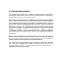
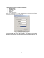
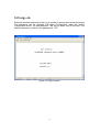
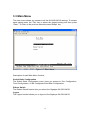
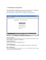
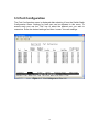
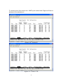
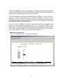
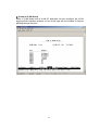
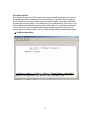
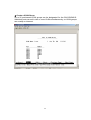
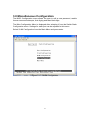
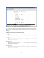
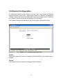
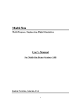
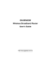
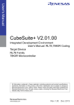
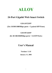
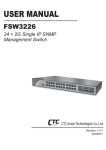
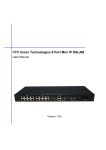
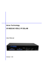
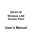
GN-GSV2401S SWITCHING HUB USER GUIDE Gigabyte Ethernet Switching Hub with 24 10/100 Mbps Fast Ethernet Ports plus 2 Gigabit Ports Rev. 1.0 Copyright ©2003 Gigabyte Technology Co., Ltd. All Rights Reserved. FCC Warning This equipment has been tested and found to comply with the limits for a Class A digital device, pursuant to Part 15 of the FCC Rules. These limitations are designed to provide reasonable protection against harmful interference in a residential installation. This equipment generates, uses and can radiate radio frequency energy and, if not installed and used in accordance with the instructions, may cause harmful interference to radio communications. However, there is no guarantee that interference will not occur in a particular installation. If this equipment does cause harmful interference to radio or television reception, which can be determined by turning the equipment off and on, the user is encouraged to try to correct the interference by one or more of the following measures: • • • • • Reorient or relocate the receiving antenna. Increase the separation between the equipment and receiver. Connect the equipment into a different outlet from the one the receiver is connected to. Consult your local distributors or an experienced radio/TV technician for help. Shielded interface cables must be used in order to comply with emission limits. Changes or modifications to the equipment, which are not approved by the party responsible for compliance, could affect the user’s authority to operate the equipment. CE Mark Warning This is a Class A product. The product may cause radio interference in a domestic environment or residential area. If interference does occur, the user may need to take appropriate actions to counteract this interference. Copyright ©2003 All Rights Reserved. This publication, including all photographs, illustrations and software, is protected under international copyright laws, with all rights reserved. Neither this manual, nor any of the material contained herein, may be reproduced without the express written consent of the manufacturer. Disclaimer The information in this document is subject to change without notice. The anufacturer makes no representations or warranties with respect to the contents hereof and specifically disclaims any implied warranties of merchantability of fitness for any particular purpose. Furthermore, the manufacturer reserves the right to revise this publication and to make changes from time to time in the content hereof without obligation of the manufacturer to notify any person of such revision or changes. Gigabyte has an on-going policy of upgrading its products and it may be possible that information in this document is not up-to-date. Please check with your local distributors for the latest information. No part of this document can be copied or reproduced in any form without written consent from the company. Trademarks All trade names and trademarks are the properties of their respective companies and are acknowledged. Contents CHAPTER 1 GETTING STARTED ........................................................................................... 1 1.1 UNPACKING INFORMATION CHECKING YOUR ITEMS .................................................. 2 1.2 HOW TO USE THIS GUIDE ............................................................................................ 3 CHAPTER 2 INTRODUCTION TO THE GIGABYTE 2+24 PORTS 10/100/1000 MBPS GIGABYTE SWITCHING HUB ...................................................... 4 2.1 GENERAL DESCRIPTION ............................................................................................. 5 2.2 KEY FEATURES........................................................................................................... 6 2.3 THE FRONT PANEL ..................................................................................................... 7 2.4 THE REAR PANEL ....................................................................................................... 9 CHAPTER 3 INSTALLING AND USING THE GIGABYTE SWITCHING HUB10 3.1 LOCAL CONSOLE MANAGEMENT ............................................................................. 11 3.2 LOG—IN .................................................................................................................. 15 3.3 MAIN MENU ............................................................................................................ 16 3.4 SWITCH STATIC CONFIGURATION ............................................................................. 17 3.5 PORT CONFIGURATION ............................................................................................. 18 3.6 TRUNK CONFIGURATION .......................................................................................... 21 3.7 VLAN CONFIGURATION .......................................................................................... 23 3.8 MISC CONFIGURATION ............................................................................................. 31 3.9 RESTART CONFIGURATION ....................................................................................... 34 CHAPTER 4 PRODUCT SPECIFICATIONS ......................................................................36 4.1 PRODUCT SPECIFICATIONS FOR 10/100BASE-X PORT FUNCTIONS .......................... 37 4.2 PRODUCT SPECIFICATIONS FOR 10/100/1000 BASEX PORT FUNCTIONS.................. 37 4.3 PRODUCT SPECIFICATIONS FOR SWITCHING FUNCTIONS .......................................... 37 4.4 PRODUCT SPECIFICATION FOR MANAGEMENT FUNCTIONS ....................................... 38 4.5 PHYSICAL SPECIFICATION ........................................................................................ 38 Chapter 1 Getting Started 1 1.1 Unpacking Information, Checking Your Items Thank you for purchasing this powerful, high-performance Gigabyte 2+24 ports 10/100/1000 Mbps Gigabyte Switching Hub. Before getting started, please check the package to make sure all the following items are included. The package should include the following: • Gigabyte GN-GSV2401S Switching Hub • AC power cord • User’s Guide for the Gigabyte Switching Hub • Mounting Kit containing: - Rubber feet for placing the switching hub on a table or flat surface - Two mounting brackets - Screws for attaching the brackets to the switching hub - Power cables If you are missing any of the items listed above, please contact your local distributor or authorized reseller. Figure 1.1 The Gigabyte GN-GSV2401S Switching Hub 2 1.2 How to use this Guide The Gigabyte GN-GSV2401S User’s Guide is divided into the follow chapters: • Chapter 2, Introduction contains a general description and key functions of the 2+24 ports 10/100/1000 Mbps Gigabyte Switching Hub. • Chapter 3, Installation explains the set-up procedures to make the gigabyte switching hub operational. • Chapter 4, Product Specifications contains information about the technical aspects of the gigabyte switching hub. • Appendices, including Contact Information and Warranty Statement. Read only if necessary. 3 Chapter 2 Introduction to the Gigabyte 2+24 Ports 10/100/1000 Mbps Gigabyte Switching Hub 4 2.1 General Description The Gigabyte GN-GSV2401S is a powerful, high-performance, Fast Ethernet switching hub, which acts as traffic controller for 24 local routes and 2 highways to connect your networks to other outside networks. With all 24 ports capable of 10 or 100 Mbps auto-negotiation operation (NWay) and 2 Gigabit Ethernet uplink ports, the switching hub can automatically negotiate with the connected partners for the network speed and duplex mode. It is ideal for micro-segmenting large networks into smaller, connected subnets for improved performance, enabling bandwidth-demanding multimedia, imaging and database applications. Moreover, the 10/100Mbps auto-sensing ability provides an easy way to migrate 10Mbps to 100 Mbps network with ease. Compared to the shared 10Mbps or 100Mbps networks, the switching hub delivers a dedicated 10/100Mbps connection to every attached client with no bandwidth congestion issues and the most cost-effective way to invest in your network’s performance in the long run. Store-and-forward switching mode guarantees low latency, plus eliminates all network errors, including runt and CRC error packets. To work under fullduplex mode, transmission and reception of the frames can occur simultaneously without causing collisions, as well as doubling the network bandwidth. The switching hub is plug-and-play without needing any software to configure, and is also fully compliant with all kinds of network protocols. Moreover, the abundant diagnostic LEDs on the front-panel provide the operating status of individual ports and the entire system. 5 2.2 Key Features The Gigabyte Switching Hub provides the following key features: • Twenty-four non-blocking 10/100 Mbps Auto-negotiation Ethernet ports • Two non-blocking 10/100/1000 Mbps Auto-negotiation Ethernet ports • Full or Half duplex transfer mode for each port • Complies with the Flow Control support for Full-duplex specifications of the IEEE802.3x standard • Complies with Port-Based VLAN, tag based VLAN with either IVL or SVL support specifications of the IEEE802.1q standard • Complies with Two-Level priority Queuing support specifications of the IEEE802.1p standard • Complies with Rapid Reconfiguration for fast address migration to support specifications of the IEEE802.1w standard • Supports static Port Trunking • Supports Store-and-Forward switching scheme • Prevents Head of Line (HOL) blocking • Supports 14K Mac address table, 4K VLAN table entries • RS-232 port interface for Console management & System configuration • Controls Ingress & Engress rate 6 2.3 The Front Panel The front panel of the Gigabyte Switching hub is shown below. Figure 2.1 Overview of Front Panel Reset button Pressing the reset button will reboot the entire system. Gigabit Port The 2 gigabit ports are used to connect to a PC or can be used to expand your network by simply connecting to a 1000 Mbps switch or Hub. Ethernet Port There are 24 Fast Ethernet ports, each capable of being connected to network devices, such as PCs and printer servers, at 10/100 Mbps. LEDs POWER On When the Power LED light is on, the GN-GSV2401S is receiving power. Off When the Power LED light is off, the power cord is improperly connected. Ports 1-24 LEDs Port LED indicators shows the operating status of each port. LNK/ACT/SPEED LED Every port has a Link/Activity/Speed LED. Green light The connection speed is operating at 100Mbps. Orange light The connection speed is operating at 10Mbps. Blinking The port is transmitting or receiving data on the 10/100Mbps Ethetnet network. A steady light (link state) indicates that the port has good linkage to its associated device. If the port is connected but the Link/Activity/Speed LED does not light up, please check the following items: 1. The switching hub and the connected devices’ power are on. 2. The port’s cable is firmly seated in its connectors in the switching hub and in the associated device. 3. The connecting cable is functional and the correct type. 4. The connecting device, including any network adapter, is functioning properly. 7 FDX/COL LED Green light A steady green light indicates the port is operating in full-duplex mode. Dark light A dark light indicates the port is operating in half-duplex mode. Blinking A collision is detected. Two Gigabit Ports LEDs LNK/ACT LED Green light The port is successfully connected to a network. Blinking The port is actively operating. 10/100/1000 LED Green light The connection speed is operating at 1000Mbps. Orange light The connection speed is operating at 100Mbps. Dark light The connection speed is operating at 10Mbps. FDX/COL LED Green light A steady green light indicates the port is operating in full-duplex mode. Dark light A dark light indicates the port is operating in half-duplex mode. Blinking A collision is detected. Serial Port This is where you will connect the RS-232 serial port to your PC for configuring the smart function. (Please see Chapter 4.4 Management Functions for more details) 8 2.4 The Rear Panel On/Off switch After plugging in the power source with the power cable, you may turn the switch to “I” for on and “O” for off. Power socket for connecting the power For compatibility with electric service in most areas of the world, the switching hub’s power supply automatically adjusts to line power in the range 100-240 VAC and 50~60 Hz. Plug the female end of the power cord firmly into the receptacle on the rear panel of the switching hub. Plug the other end of the power cord into an electric service outlet. The device is now ready to be turned on. 9 Chapter 3 Installing and Using the Gigabyte Switching Hub 10 3.1 Local Console Management You can manage the Switch locally using HyperTerminal; simply connect the Switch to a PC or workstation through the serial port. The serial port settings need to be configured before connecting to the Switch. In order to change the settings of your port, run the HyperTerminal program. This program comes packaged with Windows, but it may not be installed on your computer. It should be located as is shown below (varies according to operating systems). If it is not, consult your Windows’ documentation for instructions on installing HyperTerminal. To enable communications with the Switch, the serial cable must be connected between the Switch and the computer. Make sure both the Switch and the computer are powered down. Next, plug one end of the serial cable into the console port of the GN-GSV2401S and the other end of the serial cable into the COM1 port on the back panel of your computer. Now start your computer and turn on the GN-GSV2401S power. After the power is turned on, please select All Programs from the Start menu. Then choose Accessories, followed by Communications. In the Communications sub-menu select HyperTerminal. Figure 3.1 HyperTerminal Path 11 Please enter a name which you like for this connection, then press “OK”. Figure 3.2 Connection Description In the bottom drop down box labeled Connect using:, click the arrow and choose the COM port that the GN-GSV2401S will be connected to. In the example below, COM1 is the port selected. Press the “OK” button. Figure 3.3 Dialup info. 12 The console port is set for the following configuration: • Baud rate: 9,600 • Data width: 8 bits • Parity: none • Stop bits: 1 • Flow Control: None Make sure the terminal or PC you are using to make this connection is configured to match these settings and then press “OK”. Figure 3.4 Console Port Properties You will now be taken to the Set-Up page of the Gigabyte GN-GSV2401S Switching Hub, from where you can configure the GN-GSV2401S.(see figure 3.5) 13 Figure 3.5 System Diagnosis 14 3.2 Log—in Enter the required password in the Log-in screen to access the command console. The password can be changed from Misc Configuration under the Switch Configuration menu. You can press the “Tab” key or “Enter” key to next item. The default username is “admin” and password is “123”. Figure 3.6 Log-in screen 15 3.3 Main Menu The main menu allows you access to all the GN-GSV2401S settings. To access each setting press the “Tab” key to select the desired setting and then press “Enter”. To return to the previous selection press “BkSpc” key. Figure 3.7 Main Menu Description of each Main Menu function: Switch Static Configuration The Switch Static Configuration menu gives you access to Port Configuration, Trunk Configuration, VLAN Configuration and Misc Configuration. Reboot Switch The Reboot Switch function lets you reboot the Gigabyte GN-GSV2401S. Logout The Logout function allows you to logout of the Gigabyte GN-GSV2401S. 16 3.4 Switch Static Configuration The Switch Static Configuration menu gives you access to Port Configuration, Trunk Configuration, VLAN Configuration and Misc Configuration. Select Switch Static Configuration from the Main Menu and press Enter. Figure 3.8 Switch Static Configuration Port Configuration Enables any port, enables/disables flow control, and sets communication mode to auto-negotiation, full duplex, or half duplex. Trunk Configuration Specifies ports to group into aggregate trunks. VLAN Configuration The VLAN Configuration menu allows changes to be made to VLAN settings. Misc Configuration The Misc Configuration menu allows you to edit UserInfo, Retry Forever, Auto-aging, Mac Hash Algo settings. 17 3.5 Port Configuration The Port Configuration menu is displayed after selecting it from the Switch Static Configuration menu. Settings for each port can be adjusted in this menu. To access each port use the “Tab” key to select the desired port you wish to customize. Enter the desired settings and then “<save>” the new settings. Figure 3.9 Port Configuration Port 1-8 18 To access ports 9-24 and the two 1000Tx ports select Next Page and Enter to advance to the desired port. Figure 3.10 Figure 3.11 Ports9-16 Ports 17-24 19 Figure 3.12 1000Tx 1-2 20 3.6 Trunk Configuration The Port Trunk Configuration Menu is displayed after selecting it from the Switch Static Configuration menu. Settings for each port can be adjusted in this menu. Port trunk groups are used to combine a number of ports together to make a single high-bandwidth data pipeline. Select Trunk Configuration from the Main Menu and press enter. Figure 3.13 Port Trunk Configuration 21 Changing Port Trunking settings: To access each setting use the “Tab” key to select the desired port you wish to customize. Enter the desired settings and then “<save>” the new settings. The GN-GSV2401S can utilize up to 7 trunk groups. With up to 4 ports in each group, a potential bit rate of 800 Mbps can be achieved. Note: If the two Gigabit Ethernet ports are used as a trunk group and either port is disconnected, packets intended for the disconnected port will be dropped. Figure3.14 Trunking Port Setting menu 22 3.7 VLAN Configuration The VLAN Configuration menu allows users to configure the Gigabyte GN-GSV2401S into their networks. VLANs can be assigned to different ports. Only one untagged VLAN can be assigned to one port alternatively multiple tagged VLANs can be assigned to the same port. The VLAN Configuration Menu is displayed after selecting it from the Switch Static Configuration menu. Settings for each port can be adjusted in this menu. Ports can be combined to create high speed trunks. Select VLAN Configuration from the Main Menu and press Enter. Figure 3.15 VLAN Configuration 23 Figure 3.16 VLAN Configuration There are two most popular VLAN implementation, IEEE 802.1q Tagged VLAN and Port-based VLAN. GN-GSV2401S supports both VLAN implementation. The biggest difference between both VLAN implementations is Tagged VLAN can cross Layer-2 switch but Port-based VLAN can not. IEEE802.1q VLAN IEEE 802 Local Area Networks (LANs) of all types may be connected together with Media Access Control (MAC) Bridges, as specified in ISO/IEC 15802-3. This standard defines the operation of Virtual LAN (VLAN) Bridges that permit the definition, operation and administration of Virtual LAN topologies within a Bridged LAN infrastructure. There are two key components to understanding IEEE 802.1Q VLANs - Port VLAN ID numbers (PVID) and VLAN ID numbers (VID). Although both variables are assigned to a switch port, there are important differences between them. For instance, a user can only assign one PVID to each switch port. When packets have to be forwarded to another switch port or somewhere else on the network, the PVID defines the relevant VLAN recipient. On the other hand, a user can define a port as a member of multiple VLANs (VIDs) thus allowing the connected segment to receive packets from many VLANs on the network. 24 These two variables control a port’s ability to transmit and receive VLAN traffic. The difference between them provides network segmentation, while still allowing resources to be shared across more than one VLAN. Take for example a packet that is transmitted by a machine on Port 1 that is a member of VLAN 2 and has the Port VLAN ID number 2 (PVID=2). If the destination lies on another port (found through a normal forwarding table lookup), the switch then looks to see if the other port (Port 10) is a member of VLAN 2 (and can therefore receive VLAN 2 packets). If port 10 is not a member of VLAN 2, then the packet will be dropped by the switch and will not reach it’s destination. If Port 10 is a member of VLAN 2, the packet will go through. This selective forwarding feature based on VLAN criteria is how VLANs segment networks. The key point being that Port 1 will only transmit on VLAN 2, because it’s Port VLAN ID number is 2 (PVID=2). VLAN Configuration You can assign the PVID for any ports in a domain. 25 Create a VLAN Group Enter a VLAN Name and a VLAN ID, and then you can configure the VLAN tagging which indicates whether or not VLAN tags will be included on frames passing through this port. 26 Edit/Delete a VLAN Group You can modify or delete the settings for an existing VLAN. 27 Port-Based VLAN Port-based VLANs are VLANs where the packet forwarding decision is based on the destination MAC address and its associated port. You must define outgoing ports allowed for each port when using port-based VLANs. Note that VLAN only governs the outgoing traffic, in the other word, it is unidirectional. Therefore, if you wish to allow two subscriber ports to talk to each other, e.g., between conference rooms in a hotel, you must define the egress (outgoing port) for both ports. An egress port is an outgoing port, that is, a port through which a data packet leaves. VLAN Configuration 28 Create a VLAN Group Up to 26 port-based VLAN groups can be designated for the GN-GSV2401S. Individual ports can exit in two or more VLANs simultaneously, so VLAN groups can overlap or intersect. 29 Edit/Delete a VLAN Group You can modify or delete the settings for an existing VLAN. 30 3.8 Miscellaneous Configuration The MISC Configuration menu allows the user to edit a new password, enable forever reconnect attempts, Auto Aging and Mac Hash Algo. The Misc Configuration Menu is displayed after selecting it from the Switch Static Configuration menu. Settings for each port can be adjusted in this menu. Select VLAN Configuration from the Main Menu and press enter. Figure 3.17 VLAN Configuration 31 Figure 3.18 MISC Configuration Menu To access each setting use the “Tab” key to select the desired setting and then press “Enter”. Enter the desired settings and then press “Enter” to save the new settings. Description of each Misc Configuration function: UserName Enter the user name here. (It is a text string with a maximum of 10 alphanumeric characters.) Old Passwd Enter the old password here. (It is a text string with a maximum of 10 alphanumeric characters.) New Passwd Enter the new password here. (It is a text string with a maximum of 10 alphanumeric characters.) Passwd Again Enter the new password again here. (It is a text string with a maximum of 10 alphanumeric characters.) 32 Retry Forever The "Retry Forever" is used in the 10H /100H Mode which will retry 16 times in case of collision drop. Auto-Aging The time the Gigabyte GN-GSV2401S will retain a MAC address that has had no buffer memory activity. Mac Hash Algo Under this option two settings are possible: CRC-Hash or DirectMap. 33 3.9 Restart Configuration To access the Restart screen functions, use the “Tab” key to select the desired function and then press “Enter”. Select either “Default” or “Restart”. Selecting the “Default” function will return all settings and values to the default setup. Selecting the “Restart” function will restart the Gigabyte GN-GSV2401S. The Restart function is accessed from the Switch Static Configuration menu. Figure 3.19 Restart Configuration Menu Default The Default option will reset the Gigabyte GN-GSV2401S to the original factory settings. Restart The Restart option will restart the Gigabyte GN-GSV2401S. 34 Figure 3.20 Reboot After a successful reboot the System Diagnosis menu will reappear. Figure 3.21 System Diagnosis 35 Chapter 4 Product Specifications 36 Standards: IEEE802.3, IEEE802.3u, IEEE802.3x, IEEE802.3z, and IEEE802.3ab Interface: Twenty-four 10/100 Mbps NWay ports Two 1000 Base ports NWay Protocal support: Network speed: 10M, 100M and 1000 Mbps Duplex mode: Full and Half (10M/100Mbps) Full (1000 Mbps) 4.1 Product Specifications for 10/100BASE-X port Functions • Fully compliant with IEEE802.3 10BASE-T, and IEEE802.3u 100BASE-TX • All ports support Auto-negotiation • IEEE802.3x compliant Flow Control support for Full-duplex • Collision-based and carrier-based backpressure support for halfduplex 4.2 Product Specifications for 10/100/1000 BASEX port Functions • Fully compliant with IEEE802.3z 1000BASE-SX, and IEEE802.3ab 1000BASE-T • All ports support Auto-negotiation • Full/Half duplex support • IEEE802.3x compliant Flow Control support for Full-duplex ports 4.3 Product Specifications for Switching Functions • IEEE802.1q port-based vlan, tag-based vlan with either IVL or SVL support • IEEE802.1p two-level priority queuing support • IEEE802.1w rapid reconfiguration for fast address migration to support • static port trunking support • store-and-forward packet switching support • by-port egress/ingress rate control • head of line (hol) blocking prevention support • 14k mac address table, 4k vlan table entries support • three scheduling schemes: fcfs, strictly priority scheduling and weighted round robin scheduling to support 37 4.4 Product Specification for Management Functions • RS-232 port interface for Console management & System configuration Console Program The 24 port switch has an RS-232 console port for direct console management (RS-232 DB-9), DTE/male connector) When connecting a terminal directly to the switching hub, use either a null modem cable or a null modem adapter on a serial (straightthrough) cable. 4.5 Physical Specification Power Supply : 110 ~ 220 V Operation Environment : Operation Temperature : 0 ~ 40 °C Storage Temperature : -20 ~ 65 °C Dimension (W x L x H) : 440mm x 250mm x 45mm Weight : Gross Weight 3500 ± 5 g 38 Limited Warranty 1-Year Warranty Gigabyte warrants to the original consumer/purchaser that the adapter product free from defects in material and workmanship for no limited time from the original manufactory shipment date. This warranty does not cover the product if it is damaged in the process of being installed or improperly used. Gigabyte may replace or repair the adapter product with either new or reconditioned parts. Repaired or replaced adapter products will be returned to you at the same revision level as received or higher at Gigabyte’s option. Gigabyte reverses the right to replace discounted adapter products with an equivalent generation adapter product. KEEP THIS STUB FOR YOUR PURCHASING RECORD Customer: Phone No: Address: Email: Model: Serial: Date of Purchase: Place of Purchase: From Whom: Distributor: Customer Satisfaction GIGA-BYTE TECHNOLOGY CO., LTD. No.6, Bau Chiang Road, Hsin-Tien, Taipei Hsien, Taiwan, R.O.C. Tel: 886-2-89124888 Fax:886-2-89124007 http://www.gigabyte.com.tw Technical Support E-mail: [email protected] TEL: 886-2-89124888 39