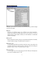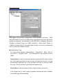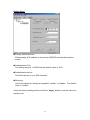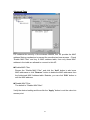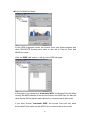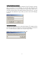
1
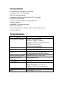
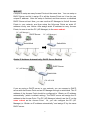
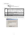
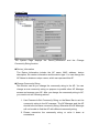
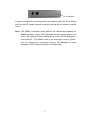
GN-AP101B
Wireless Access Point
User Guide
http://www.gigabyte.com.tw
Rev.1.1
Safety, Care and Regulatory Information
Important safety instructions
Read and follow all instructions marked on the product and in the
documentation before you operate your system. Retain all safety and
operating instructions for future use.
l The product should be operated only from the type of power source
indicated on the rating label.
l The plug-socket combination must be accessible at all times because it
serves as the main disconnecting device.
l All products hipped with a three-wire electrical grounding-type plug only
fits into a grounding-type power outlet. This is a safety feature. The
equipment grounding should be in accordance with local and national
electrical codes. The equipment operates safely when it is used in
accordance with its marked electrical ratings and product usage
instructions
l Do not use this product near water or a heat source.
l Set up the product on a stable work surface or so as to ensure stability of
the system.
l Openings in the case are provided for ventilation. Do not block or cover
these openings. Make sure you provide adequate space around the
system for ventilation when you set up your work area. Never insert
objects of any kind into the ventilation openings.
l To avoid electrical shock, always unplug all power cables and modem
cables from the wall outlets before removing covers.
l Allow the product to cool before removing covers or touching internal
components.
l Use only the power cord and batteries indicated in this manual. Do not
dispose of batteries in a fire. They may explode. Check with codes for
possible special disposal instructions.
Precautions for Products With Modems, Telecommunications, or Local
Area Network Options
Observe the following guidelines when working with options:
• Avoid using a telephone (other than a cordless type) during an electrical
storm. There may be a remote risk of electric shock from lightning.
• CAUTION - To reduce the risk of fire, use only No. 26 AWG or larger
•
telecommunication line cord.
Do not plug a modem or telephone cable into the network interface
•
•
•
controller (NIC) receptacle.
Disconnect the modem cable before opening a product enclosure,
touching or installing internal components, or touching an uninsulated
modem cable or jack.
Do not use a telephone line to report a gas leak while you are in the
vicinity of the leak.
Do not use this product near water, for example, near a bathtub,
washbowl, and kitchen sink or laundry tub, in a wet basement or near a
swimming pool.
Federal Communications Commission (FCC) Statement
Note: This equipment has been tested and found to comply with the limits for a
Class B digital device, pursuant to Part 15 of the FCC Rules. These limits are
designed to provide reasonable protection against harmful interference when
the equipment is operated in a commercial environment. This equipment
generates, uses, and can radiate radio frequency energy and, if not installed
and used in accordance with the instruction manual, may cause harmful
interference to radio communications. Operation of this equipment in a
residential area is likely to cause harmful interference in which case the user
will be required to correct the interference at his own expense.
Properly shielded and grounded cables and connectors must be used in order
to meet FCC emission limits. Neither the provider nor the manufacturer are
responsible for any radio or television interference caused by using other than
recommended cables and connectors or by unauthorized changes or
modifications to this equipment. Unauthorized changes or modifications could
void the user's authority to operate the equipment.
This device complies with Part 15 of the FCC Rules. Operation is subject to the
following two conditions:
(1) This device may not cause harmful interference, and
(2) This device must accept any interference received, including interference
that may cause undesired operation.
/ For European users only /
European Community Directive Conformance Statement
This product is in conformity with the protection requirements of EC Council
Low Voltage Directive (Safety) 73/23/EEC, EMC Directive 89/336/EEC on the
approximation of the laws of the Member States relating to electro-magnetic
compatibility.
FCC Radiation Exposure Statement
This equipment complies with FCC radiation exposure limits set forth for an
uncontrolled environment. In order to avoid the possibility of exceeding the
FCC radio frequency exposure limits, human proximity to the antenna shall not
be less than 20cm (8 inches) during normal operation. Proposed RF exposure
safety information to include in User’s Manual.
Contents
1. INTRODUCTION....................................................................................................1
1-1. CONTENTS OF YOUR SHIPMENT ...........................................................................1
1-2. PHYSICAL INTERFACE ..........................................................................................2
1-3. ACCESS POINT LED I NDICATORS .........................................................................2
1-4. KEY FEATURES .....................................................................................................3
1-5. SPECIFICATIONS ...................................................................................................3
2. INSTALLATION......................................................................................................4
3. ACCESS POINT MANAGER ................................................................................7
3-1. INSTALLING THE ACCESS POINT MANAGER.........................................................7
3-2. USING THE ACCESS POINT MANAGER ................................................................12
4. UPGRADE FIRMWARE......................................................................................30
5. UNINSTALL AP MANAGER UTILITY............................................................32
1. Introduction
GN-AP101B access point makes wireless networking a practical reality in
more places, more companies and more environments than ever. Thanks to
robust, secure, industry-standard 802.11b wireless networking, you can build
networks that were previously far too expensive or too complex.
The Gigabyte Wireless system can connect PCs throughout your premises
without the headache of running cable. It’s an effective way to tie together
laptop PCs, mobile workers, floating workers, temporary workers and offices.
It’s the ideal way to provide Internet and Ethernet connectivity to lecture halls,
warehouses, retail sales floors, gymnasiums and factories, including large
spaces where radio transmission echo has previously been a problem.
1-1. Contents of Your Shipment
Before the installation procedures, please ensure the components are not
damaged during the shipping. The shipment of the GN-AP101B includes:
-
One GN-AP101B Wireless Access Point
One AC Power Adapter
One Installation CD with the AP Manager and User Guide Soft Copy
One User Guide
One RJ45 cable
Please contact your local distributor or authorized reseller immediately for any
missing or damaged components. If you require returning the damaged
product, you must pack it in the original packing material or the warranty will be
voided.
1
1-2. Physical Interface
w One Ethernet LAN Port
RJ-45, Auto -sensing and Auto-MDI/MDIX for 10/100M Ethernet LAN
connection
w Init Button
Initial reset (Init to factory default)
w Wireless antenna
One 2.4 GHz antenna - IEEE802.11b
w Wireless solution
Intersil Prism2.5
w Power
1-3. Access Point LED Indicators
w Power LED (Green light)
The Power LED lights up when power is on.
w Wireless LED (Green light)
On
The wireless function is acting.
Flicker Data is being transmitted/received.
w LAN LED (Link/Act: Green light)
On
The LED will light up if connected to a link partner.
Flicker Data is being transmitted/received.
w Status LED
Green light
Off
Red light
When reset or power on.
The system is ready.
System error
2
1-4. Key features
w Compatible with IEEE 802.11b Standard
w Auto data rate for 11/5.5/2/1Mbps
w 802.1D transparent Bridge
w Operation Channels for US/Canada, ETSI, and Japan.
w Support Nonpublic SSID
w Firmware update through AP manager By TFTP
w Roaming support
w MDI/MDIX: Auto crossover detect
w DHCP Client support
w Support Passphrase string Key. 40(64), 128 bits WEP privacy
w Support MAC filter
1-5. Specifications
Feature
Communication Standard
Value
Protocol Support
IEEE802.11b Wireless LAN
IEEE 802.3 10 Base-T Ethernet
IEEE 802.3u 100 Base-TX Fast Ethernet
IEEE 802.3x Flow Control
IEEE 802.3 Auto Negotiation
TCP/IP, DHCP, UDP, ICMP, ARP.
CPU
Arm9 32 bit. RISC controller
Interfaces
Ethernet 10/100 Mbps LAN port with
Auto-negotiation and auto -MDIX function
Network Operation System Win95/98/2000/NT/XP, Unix, Linux
Operation System for
AP Manager
Win95/98/2000/NT/XP
Power Supply
Operation Environment
5V DC 2A
Operation Temperature : 0 ~ 40 ?C
Storage Temperature : -20 ~ 65 ?C
Humidity: 5%~90% (Non-condensing).
Dimension (W x L x H)
Weight
110 mm x 160mm x 25 mm (device only)
Gross Weight 115 ±5 g
3
2. Installation
Follow these steps to install the GN-AP101B Wireless Access Point.
1. Choose a proper place for GN-AP101B Wireless Access Point. In general,
the best location is at the center of your wireless coverage area, within line
of sight to all wireless devices. Keeping clear of metal obstructions and
away from direct sunlight.
2. Place the GN-AP101B in the desired location. Normally, the higher you
place the antenna, the better the performance will be. The antenna’s
position enhances the receiving sensitivity.
3. Attach one end of an RJ -45 Ethernet cable to the GN-AP101B and attach
the other end to a network hub, switch, router, or patch panel (possibly on a
wall).
4. Attach one end of the AC power adapter to the GN-AP101B and the other
end to a power outlet. (Note: Only use the power adapter supplied by
Gigabyte in the product package. Using a different adapter may result in
product damage.)
For the average home, signal range should not be an issue. If you experience
low or no signal strength in areas of your home that you wish to access,
consider positioning the Access Point in a location directly between the
computers with wireless adapters. Additional Access Points can be connected
to provide better coverage in rooms where the signal does not appear as
strong as desired.
4
There are two installation mode for your reference as follow:
Static IP address
Method 1
If you are Not using a DHCP server in your network, you can configure the AP
by connecting to the computer directly.
PC (AP Manager)
192.168.1.x
DHCP (Disable)
192.168.1.1(default)
GN-AP101B
1. You will need to assign a Static IP Address to the computer that you are
using to configure the Access Point on the same subnet. For instance, the
default IP address of the Access Point is 192.168.1.1 and the subnet mask
255.255.255.0. You can enter IP address 192.168.1.20 (assuming that it is
not already assigned to another network device), subnet mask
255.255.255.0 to your computer.
2. Connect to the Access Point one by one and assign a static IP to each
Access Point. For example, 192.168.1.2 or 192.168.1.y, etc. (If the IP
address of your network is 10.1.5.x then your Access Point can be
assigned to 10.1.5.y.)
3. Make sure that every Access Point has a unique IP.
4. After all Access Points have been configured successfully, then you can
use AP Manager to control/monitor all Access Points network.
PC (AP Manager)
192.168.1.x
… … ..
192.168.1.1
192.168.1.2
5
192.168.1.y
Method 2
If require to setup as many Access Points at the same time. You can setup a
DHCP Server and let it assign IP to all the Access Points so it has its own
unique IP address. After the setup is finished, and then remove or disabled
DHCP Server at last. Now, you can use the AP Manager to find all Access
Points in your network, and then setup the N-Access Points as static IP
address one by one. Notice: After assign static IP address to every Access
Points, be sure to set the PC (AP Manager) to the same subnet.
PC (AP Manager)
PC (AP Manager)
DHCP Server
Switch/Hub
Switch/Hub
… … ..
… … ..
Obtain IP Address Automatically - DHCP Server Enabled
DHCP Server
PC (AP Manager)
Switch/Hub
GN-AP101B
If you are using a DHCP server in your network, you can connect a DHCP
server with the Access Point and an AP Manager through a switch/hub. The IP
address of the Access Point should be configured to “Obtain an IP address
automatically” (which is default setting). The DHCP server will assign the IP
address to the Access Point. The PC (AP Manager) should use the IP on the
same subnet as the Access Point. Or, you can configure the PC (AP
Manager) to “Obtain an IP address automatically” and assign IP by the same
DHCP server.
6
3. Access Point Manager
The Gigabyte Access Point Manager is used to configure Gigabyte Access
Points.
Note: The performance of wire line link is better than wireless link between the
AP Manager and each Access Point. To use the wire line link to
manage the Access Point is recommended.
3-1. Installing the Access Point Manager
Please follow these steps to install the Gigabyte AP Manager in the Windows.
Step1. Insert the installation CD and click Install Gigabyte AP Manager on
the CD autorun screen.
Step2. Please wait a while!!
7
Step3. Click “Next”.
Step4. Type the User Information then click “Next”.
8
Step5. Click “Next” to accept the default directory or “Browse” to another
location.
Step6. Click “Next”.
9
Step7. Click “Next”.
Step8. Please wait a while.
10
Step9. Click “Finish” to complete setup.
11
3-2. Using the Access Point Manager
You can launch Gigabyte AP Manager through Start \ Programs \ Gigabyte
AP Manager Utility \ Gigabyte AP Manager.
Enter the default password “admin” and click “OK”.
It will automatically search for Access Points on the same subnet when you
open the Gigabyte AP Manager. You may click the icon
Access Points manually.
to searching for
Menu bar
Tool bar
Page control
Tree view
Status bar
Progress bar
12
n Tree structure
ESSID (ap101b)
AP Name (AP101B)
MAC Address (0020ED001700)
n Menu bar
Tools
Allow you to “Search” for AP by ESSID, AP Name, MAC
Address, and IP Address and “Connect to AP by IP”. And allow
you to “Save”, “Load” the AP configuration and “Copy”, “Paste”
the configuration at the current page. Besides, it includes both
“System Reboot” and “Load Default”.
Password Allow you to change the AP Manager password and set the
SNMP community string.
About
An online help and the AP Manager version.
Exit
Note:
Exit the AP Manager.
When you search for AP by AP Name (Tools->Search->By AP
Name). You can press the “search next” to continue to search the
same name of AP.
13
n Tool bar
Find Access Point
Connect To AP By IP
Save AP Configuration
Load AP configuration
Page Copy
Page Paste
System Reboot
Load Default
- Find Access Point: Find all AP in the same subnet.
- Save AP Configuration: Save all setting of the AP to a temp file.
- Load AP Configuration: Load the setting of the temp file that you saved
before to the current AP.
- Page Copy: Copy the setting of the current page.
- Page Paste: Paste the setting you has copied to the current page.(You
can paste the setting of AP1 to AP2 at the same tab page.)
- System Reboot: Reboot the Access Point.
- Load Default: Set the Access Point to the manufacture default.
- Connect To AP By IP: If you want to manage the AP in the different
subnet, use this function and key in the IP.
14
System Page
The System Page displays the Device_Information and the Change
Community String function.
n Device_Information
The Device_Information include the AP name, MAC address, device
description, the version information and the device type. You can change the
AP Name to whatever unique name, which can represent this AP.
n Change Community String
This function can let you change the community string to the AP. You can
change a new community string on purpose to prohibit other AP Manager
access and manage your AP. After you change the community string to AP,
you need to do two following actions.
1. Use Password->Set Community String on the Menu Bar to set the
community string to the AP manager. The AP Manager and the AP
should have the same community string. Otherwise the AP Manager
will not be able to find the AP with different community string
2. Please memorize the community string or write it down at
somewhere.
15
Init button
In case you forget the community string, you have to press the AP init button
and then the AP setting (include community string) will be restore to default
value.
Note: The SNMP community string defines the relationship between an
SNMP manager system (AP Manager) and the agent systems (all
APs). This string acts like a password to control the AP Manager to
access the AP. The default value of the community string is “public”.
You can change the community string of AP Manager by using
Password->Set Community String on the Menu Bar.
16
IP Config Page
n Obtain an IP address automatically
You can check this selection to get IP address from the DHCP server
automatically in you network.
n Use the following IP address
You can check this selection to assign IP address by yourself. The default IP
address is 192.168.1.1 and the subnet mask is 255.255.255.0. Please make
sure the assigned IP address is unique in your network. After you change
the IP address of the AP, please also change the PC’s (AP Manager) IP
address to the same subnet. And then click the “Find Access Point” icon;
AP manager will search the AP in the network.
17
Wireless Operation Page
Normally, you can have the wireless works smoothly even you didn’t change
any item in this page.
n Region
Because of the different region has a different open channel regulation,
please check whether the default region value is your local area. If it did not
appear properly region please contact your local distributor or authorized
reseller immediately.
n Channel ID
Please choose the channel, which you can get best performance. Normally,
it doesn’t need to change. The default value is channel 11.
n Preamble Type
The preamble field shall be provided so that the receiver can perform the
necessary operations for synchronization. Under this option two setting are
possible: “Long” or “Short”. The default value is “Long”.
n Transmit Rates
You can select one of the rates among 1M, 2M, 5.5M and 11M based on
your need. The default value is “11M”.
18
n Auto Rate
In this item you can select either “enable” or “disable”. The default value is
“enable ”.
Enable: If the selection is “enable”, the transfer rate will automatically
change to the optimum rate allowed. The range of auto-change will
base on the setting of “Transmit Rate ”.
Transmit Rate setting:
11M: range is among 1M, 2M, 5,5M and 11M
5.5M: range is among 1M, 2M and 5,5M
2M: range is between 1M and 2M
1M: no auto-change. The transmit rate is fixed at 1M.
Disable: There is no transfer rate auto-change. The transfer rate will be
defined by the “Transmit Rate” column.
n Hidden ESSID
This setting allows you to hide the ESSID in wireless transmission. Those
who don’t know the ESSID will not be able connect to the AP. The default
value is “disable”.
n RTS Threshold
This value should remain at its default setting of 2432. Should you encounter
inconsistent data flow, only minor modifications are recommended. The
setting range is 0 ~ 3000.
n ESSID
The ESSID or SSID is the name represent the AP in the wireless network.
The ESSID of all AP in your network should set to identical for the mobile
client can roam between access points. This ESSID string is case sensitive
of up to 32 ASCII characters.
Verify the desired setting and then click the “Apply” butto n to set the value into
access point.
19
Encryption Page
This page is the security configuration of the wireless connection. WEP
(Wired Equivalent Privacy) is a data privacy mechanism based on a 64/128-bit
shared key algorithm, as described in the IEEE 802.1x standard. When the
“Disable” is selected there is no WEP encryption. When either “64bits” or
“128bits” selected there is encrypted date transfer to prevent unauthorized
user to access the wireless network.
n Authentication Type
You may choose between “Open System”, “Shared Key”, “Both”, “802.1x”
and “802.1x – Dynamic WEP”. The Authentication Type default is set to
“Both”.
Open System, in which the sender and the recipient do NOT share a secret
key. Each party generates its own key-pair and asks the receiver to accept
the randomly generated key. Once accepted, this key is used for a short
time only. Then a new key is generated and agreed upon.
Shared Key is both the sender and the recipient share a secret key.
If the “Shared Key” or “Both” option is selected, and then the option “Disable”
of the WEP type will be disabled.
20
802.1x authentication for wireless LANs provides centralized, server-based
athentication of end users.
1) A client sends a “start” message to an access point, which requests the
identity of the client.
2) The client replies with a response packet containing an identity, and the
access point forwards the packet to an authentication server.
3) The authentication server sends an “accept” packet to the access point.
4) The access point places the client port in authorized state, and traffic is
allowed to proceed.
It is necessary that the Radius page have to be configured if the option
“802.1x” is seleted.
If the 802.1x – Dynamic WEP option is selected, and then you only have to
choose which WEP type you want. Due to the key value will be generated by
system.
n 64 (40) Bits or 128 (104) bits
There are two levels of encryption 64 bits and 128 bits. The 64 bits
encryption is referenced as a lower level encryption. The 128 bits encryption
is referenced as a higher level encryption.
The 64 bits WEP encryption use 40 bits as a secret key, which can
controlled by user, and 24 bits as the initialize vector, which user can not
control. These two portions plus together is 64 bits encryption. Some other
vendor’s product might refer as 40 bits encryption. It is the same thing.
The 128 bits WEP encryption use 104 bits as a secret key, which can
controlled by user, and 24 bits as the initialize vector, which user can not
control. These two portions plus together is 128 bits encryption. Some other
vendor’s product might refer as 104 bits encryption. It is the same thing.
21
n Automatic Generation
Check this selection can allow user to generate the WEP key based on the
string user key in. This filed can key in up to 10 character.
If the “Automatic Generation” is not checked user can manually change the
WEP key by key in the HEX value.
Verify the desired setting and then click the “Apply” button to set the value into
access point.
22
Radius Page
n Primary RADIUS server
Please assign a IP address to the primary RADIUS server(authentication
server).
n Authentication Port
The setting range is 1~65536 and the default value is 1812.
n Authentication sercet
This filed can key in up to 256 character.
n Rekeying
Under this option two setting are possible: “enable” or “disable”. The default
value is “enable”.
Verify the desired setting and then click the “Apply” button to set the value into
access point.
23
Advanced Page
For enhance the security of the wireless network, this AP provide the MAC
address filtering mechanism to prevent the unauthorized user access. Check
“Enable MAC filter” and key in MAC address table, then only those MAC
address in the table are allowed to connect to this AP.
n Enable MAC Filter
Choose the “Enable MAC Filter” and click the “Add” button to add more
MAC addresses or click “Remove” button to delete the MAC addresses from
the Authorized MAC Address table. Besides, you can click “Edit” button to
edit the MAC address.
n Disable MAC Filter
The default is “Disable MAC filter".
Verify the desired setting and then click the “Apply” button to set the value into
access point.
24
OperationMode Page
The Access Point supports three operation modes: “Access Point”, “Point to
Point”, “Point to MultiPoint”. The default operation mode is “Access Point”.
n Access Point Mode
In this operation mode, the Access Point works as a Standard 802.11b
based access point.
n Point to Point Mode
In this WDS supported mode, the Access Point can communication with
other GIGA-BYTE Access point which is also set to Point to Point and
MultiPoint mode. You have to enter the MAC address of the host AP.
25
n Point To MultiPoint Mode
In this WDS supported mode, the Access Point can communication with
other GIGA-BYTE Access point which is also set to Point to Point and
MultiPoint mode.
Click the “WDS List” button, it will go to the WDS List page.
In this page, if you choose the "Automatic WDS", the Access Point will allow
not only the MAC Address of the Access Points in the WDS List, but also the
other Access Points that we have detected to communicate in this mode.
If you don't choose "Automatic WDS", the Access Point will only allow
the Access Points which on the WDS List to communicate in this mode.
26
The maximum number of the connectible Access Point is 8.
Click “Scan” button, the Scan Window will appear as below.
You can select which Access Point you want or choose "Select All" check
box, and then click “OK” to add those MAC Address into WDS List.
Besides, you can click “Edit” button to modify the MAC address which you
select on the WDS List or click “Remove” button to delete the MAC address
which you select on the WDS List. Or you can click the ”Cancel” button to
reserve the original value. Finally, please click “OK” button to return to the
OperationMode page and click “Apply” button to set the value into access
point.
27
Associated List Page
From this page, you will get the information of the workstation which can
connect to the AP. The form list includes the MAC Address, Signal level and
description of the workstation.
28
Change AP Manager Password
User can change the administration password of the AP manger to prevent
other user access to the AP Manager. On the Menu Bar (Password->AP
Manager Password) can invoke the password change dialog. Please enter a
new admin password and confirm admin password then press “OK”. You have
to enter this new password to log in when you want to use the AP Manager
next time.
Set Community String
The community string defines the relationship between AP manager and the
AP. This string acts like a password to control the AP Manager to access the
AP. For detail description, please refer to “System Page” section.
Please enter a community string and then press “OK”.
29
4. Upgrade Firmware
You can download the upgraded firmware version from Gigabyte website.
n Run TFTP Program
Step1.
You can find the “Upgrade Tool” through Start \ Programs \
Gigabyte AP Manager Utility \ Gigabyte AP Upgrade.
Step2. The Gigabyte Firmware Upgrade Tool screen will appear. Please
enter the “AP IP address” which you want to upgrade the firmware.
You can press “Ping” button to verify whether the AP is online.
30
Step3. Press “Open” button to choose the firmware then press “Upgrade”
button to start the firmware upgrade process.
Note: During the firmware upgrade, please DO NOT turn off the PC
or AP and DO NOT unplug the Ethernet cable.
Step4. After the AP device rebooting successful, the AP firmware upgrade is
completed.
Note:
Right-Click on the screen, the content menu will be displayed. You can
find the online help and the version information of the firmware
upgrade utility.
31
5. Uninstall AP Manager Utility
You can find the Uninstall program through Start \ Programs \ Gigabyte AP
Manager Utility \ Uninstall.
Step1. The InstallShield Wizard will appear then please wait.
Step2. Click “Yes”.
Step3. Click “OK” and then the Gigabyte AP Manager Utility has been
uninstalled successfully.
32
If you just want to modify some program components or reinstall all program
components, you can run the installation program directly. And then the
InstallShield Wizard will appear.
Please choose one of the options what you want then click “Next” continues to
modify, repair or remove the Gigabyte AP Manager Utility.
33
Limited Warranty
1-Year Warranty
Gigabyte warrants to the original consumer/purchaser that the product free
from defects in material and workmanship for no limited time from the
original manufactory shipment date . This warranty does not cover the
product if it is damaged in the process of being installed or improperly used.
Gigabyte may replace or repair the product with either new or reconditioned
parts. Repaired or replaced products will be returned to you at the same
revision level as received or higher at Gigabyte’s option. Gigabyte reverses
the right to replace discounted products with an equivalent generation
product.
KEEP THIS STUB FOR YOUR PURCHASING RECORD
Customer:
Phone No:
Address:
Email:
Model:
Serial:
Date of Purchase:
Place of Purchase:
From Whom:
Distributor:
Customer Satisfaction
GIGA-BYTE TECHNOLOGY CO., LTD.
No.6, Bau Chiang Road, Hsin-Tien, Taipei Hsien, Taiwan, R.O.C.
Tel: 886-2-89124888
Fax:886-2-89124007
http://www.gigabyte.com.tw
Technical Support
E-mail: [email protected]
34