1
User Guide
V2IU 4300T Converged
Network Appliance
V7.2.2 — May 2007
Trademark Information
Polycom®, the Polycom logo design, [and others that appear in your document] are registered trademarks of Polycom,
Inc. [List other trademarks]™ are trademarks of Polycom, Inc. in the United States and various other countries. All other
trademarks are the property of their respective owners.
© 2007 Polycom, Inc. All rights reserved.
Polycom Inc.
4750 Willow Road
Pleasanton, CA 94588-2708
USA
No part of this document may be reproduced or transmitted in any form or by any means, electronic or mechanical, for
any purpose, without the express written permission of Polycom, Inc. Under the law, reproducing includes translating
into another language or format.
As between the parties, Polycom, Inc. retains title to, and ownership of, all proprietary rights with respect to the software
contained within its products. The software is protected by United States copyright laws and international treaty
provision. Therefore, you must treat the software like any other copyrighted material (e.g. a book or sound recording).
Every effort has been made to ensure that the information in this manual is accurate. Polycom, Inc. is not responsible
for printing or clerical errors. Information in this document is subject to change without notice.
Contents
Contents
1 Introduction . . . . . . . . . . . . . . . . . . . . . . . . . . . . . . . . . . . 1–1
The Polycom V2IU 4300T Converged Network Appliance . . . . . . . . . . . . 1–1
T1 Wide Area Network (WAN) Access Router . . . . . . . . . . . . . . . . . . 1–1
Security . . . . . . . . . . . . . . . . . . . . . . . . . . . . . . . . . . . . . . . . . . . . . . . . . . . . 1–1
VoIP . . . . . . . . . . . . . . . . . . . . . . . . . . . . . . . . . . . . . . . . . . . . . . . . . . . . . . 1–1
Quality of Service . . . . . . . . . . . . . . . . . . . . . . . . . . . . . . . . . . . . . . . . . . . 1–1
Call Quality Monitoring . . . . . . . . . . . . . . . . . . . . . . . . . . . . . . . . . . . . . 1–2
Future-proof Scalability . . . . . . . . . . . . . . . . . . . . . . . . . . . . . . . . . . . . . . 1–2
Feature Summary . . . . . . . . . . . . . . . . . . . . . . . . . . . . . . . . . . . . . . . . . . . . . . . 1–2
Front Panel LEDs . . . . . . . . . . . . . . . . . . . . . . . . . . . . . . . . . . . . . . . . . . . . . . . 1–3
Back Panel . . . . . . . . . . . . . . . . . . . . . . . . . . . . . . . . . . . . . . . . . . . . . . . . . . . . . 1–3
Power Connector . . . . . . . . . . . . . . . . . . . . . . . . . . . . . . . . . . . . . . . . . . . 1–4
Erase Button . . . . . . . . . . . . . . . . . . . . . . . . . . . . . . . . . . . . . . . . . . . . . . . 1–4
Management console port . . . . . . . . . . . . . . . . . . . . . . . . . . . . . . . . . . . . 1–4
T1/E1 WAN port . . . . . . . . . . . . . . . . . . . . . . . . . . . . . . . . . . . . . . . . . . . 1–4
Ethernet WAN port . . . . . . . . . . . . . . . . . . . . . . . . . . . . . . . . . . . . . . . . . 1–5
2 Getting Started . . . . . . . . . . . . . . . . . . . . . . . . . . . . . . . . . 2–1
Physical Installation . . . . . . . . . . . . . . . . . . . . . . . . . . . . . . . . . . . . . . . . . . . . . 2–1
Desktop Installation . . . . . . . . . . . . . . . . . . . . . . . . . . . . . . . . . . . . . . . . . 2–1
Wall-Mount Installation . . . . . . . . . . . . . . . . . . . . . . . . . . . . . . . . . . . . . 2–2
Administration of the Polycom V2IU 4300T . . . . . . . . . . . . . . . . . . . . . . . . 2–2
3 Configuring the Polycom V2IU 4300T . . . . . . . . . . . . . . . . . 3–1
Configuration Guide For IP Centrex Applications . . . . . . . . . . . . . . . . . . . 3–2
Configuration Outline . . . . . . . . . . . . . . . . . . . . . . . . . . . . . . . . . . . . . . . 3–3
Configuration Guide For Station Side IP PBX Applications . . . . . . . . . . . 3–4
Configuration Outline . . . . . . . . . . . . . . . . . . . . . . . . . . . . . . . . . . . . . . . 3–5
Configuration Guide For Trunk Side IP PBX Applications . . . . . . . . . . . . 3–6
Configuration Outline . . . . . . . . . . . . . . . . . . . . . . . . . . . . . . . . . . . . . . . 3–7
Configuration Guide For Hosted Video Applications . . . . . . . . . . . . . . . . 3–7
Configuration Guide For Enterprise Video Applications . . . . . . . . . . . . 3–10
System Configuration . . . . . . . . . . . . . . . . . . . . . . . . . . . . . . . . . . . . . . . . . . 3–12
1
User Guide V2IU 4300T Converged Network Appliance
Configure the LAN Interface . . . . . . . . . . . . . . . . . . . . . . . . . . . . . . . . 3–12
Configuring VLANs in the Polycom V2IU 4300T . . . . . . . . . . . . 3–13
Modify an Existing VLAN Configuration . . . . . . . . . . . . . . . . . . 3–15
Delete an Existing VLAN Configuration . . . . . . . . . . . . . . . . . . . 3–15
Assign the Polycom V2IU 4300T’s ALG to your Priority VLAN . . .
3–16
Configure the WAN Interface . . . . . . . . . . . . . . . . . . . . . . . . . . . . . . . .
Protocol . . . . . . . . . . . . . . . . . . . . . . . . . . . . . . . . . . . . . . . . . . . . . . .
Frame Relay Mode and DLCI . . . . . . . . . . . . . . . . . . . . . . . . . . . .
Timing . . . . . . . . . . . . . . . . . . . . . . . . . . . . . . . . . . . . . . . . . . . . . . . .
Payload Loopback . . . . . . . . . . . . . . . . . . . . . . . . . . . . . . . . . . . . . .
3–16
3–18
3–18
3–19
3–19
Configure the DHCP Server . . . . . . . . . . . . . . . . . . . . . . . . . . . . . . . . . 3–19
Delete a DHCP IP Address . . . . . . . . . . . . . . . . . . . . . . . . . . . . . . 3–21
Disable The DHCP Server . . . . . . . . . . . . . . . . . . . . . . . . . . . . . . . 3–22
Configure Hostname, SNMP and Remote Logging . . . . . . . . . . . . .
Configure SNMP . . . . . . . . . . . . . . . . . . . . . . . . . . . . . . . . . . . . . . .
Disable SNMP . . . . . . . . . . . . . . . . . . . . . . . . . . . . . . . . . . . . . . . . .
Configure Remote System Logging . . . . . . . . . . . . . . . . . . . . . . .
Disable Remote System Logging . . . . . . . . . . . . . . . . . . . . . . . . . .
Configure a local Hostname . . . . . . . . . . . . . . . . . . . . . . . . . . . . .
Enable Mean Opinion Scoring (MOS) . . . . . . . . . . . . . . . . . . . . .
Set MOS Threshold . . . . . . . . . . . . . . . . . . . . . . . . . . . . . . . . . . . . .
3–22
3–23
3–23
3–23
3–24
3–24
3–24
3–24
Change the Administration Password . . . . . . . . . . . . . . . . . . . . . . . . 3–25
Read-only User . . . . . . . . . . . . . . . . . . . . . . . . . . . . . . . . . . . . . . . . . . . . . . . . 3–25
Enabling a Read-only User . . . . . . . . . . . . . . . . . . . . . . . . . . . . . . . . . . 3–25
Subinterfaces . . . . . . . . . . . . . . . . . . . . . . . . . . . . . . . . . . . . . . . . . . . . . . . . . . 3–26
How Subinterfaces Works . . . . . . . . . . . . . . . . . . . . . . . . . . . . . . . . . . . 3–26
Configuring Subinterfaces . . . . . . . . . . . . . . . . . . . . . . . . . . . . . . . . . . . 3–27
ToS Byte Setting . . . . . . . . . . . . . . . . . . . . . . . . . . . . . . . . . . . . . . . . . . . . . . . 3–28
How the ToS Byte Setting Works . . . . . . . . . . . . . . . . . . . . . . . . . . . . . 3–28
Viewing or Changing the ToS Byte Setting . . . . . . . . . . . . . . . . . . . . 3–28
H.323 Configuration . . . . . . . . . . . . . . . . . . . . . . . . . . . . . . . . . . . . . . . . . . . 3–30
H.323 Activity . . . . . . . . . . . . . . . . . . . . . . . . . . . . . . . . . . . . . . . . . . . . . 3–35
H.323 Alias Manipulation . . . . . . . . . . . . . . . . . . . . . . . . . . . . . . . . . . . 3–35
H.323 Neighboring . . . . . . . . . . . . . . . . . . . . . . . . . . . . . . . . . . . . . . . . . 3–37
Regular Expressions . . . . . . . . . . . . . . . . . . . . . . . . . . . . . . . . . . . . . . . . 3–39
Forwarding Rules . . . . . . . . . . . . . . . . . . . . . . . . . . . . . . . . . . . . . . . . . . . . . 3–40
How Forwarding Rules Works . . . . . . . . . . . . . . . . . . . . . . . . . . . . . . . 3–40
Example . . . . . . . . . . . . . . . . . . . . . . . . . . . . . . . . . . . . . . . . . . . . . . . . . . 3–40
Configuring Forwarding Rules . . . . . . . . . . . . . . . . . . . . . . . . . . . . . . 3–41
Peering Proxy . . . . . . . . . . . . . . . . . . . . . . . . . . . . . . . . . . . . . . . . . . . . . . . . . 3–43
How Peering Proxy Works . . . . . . . . . . . . . . . . . . . . . . . . . . . . . . . . . . 3–43
Configuring Peering Proxy . . . . . . . . . . . . . . . . . . . . . . . . . . . . . . . . . . 3–47
2
Contents
Adding an H.323 Prefix Entry . . . . . . . . . . . . . . . . . . . . . . . . . . . . 3–48
Clients List Lock . . . . . . . . . . . . . . . . . . . . . . . . . . . . . . . . . . . . . . . . . . . . . . . 3–50
Enabling the Clients List Lock . . . . . . . . . . . . . . . . . . . . . . . . . . . . . . . 3–50
H.323 Activity Monitor . . . . . . . . . . . . . . . . . . . . . . . . . . . . . . . . . . . . . . . . . 3–51
Type of Events . . . . . . . . . . . . . . . . . . . . . . . . . . . . . . . . . . . . . . . . . . . . . 3–52
Call Status . . . . . . . . . . . . . . . . . . . . . . . . . . . . . . . . . . . . . . . . . . . . . . . . 3–52
Call Termination . . . . . . . . . . . . . . . . . . . . . . . . . . . . . . . . . . . . . . . . . . . 3–54
Viewing the H.323 Activity Monitor . . . . . . . . . . . . . . . . . . . . . . . . . . 3–55
VoIP Configuration . . . . . . . . . . . . . . . . . . . . . . . . . . . . . . . . . . . . . . . . . . . . 3–56
Configure the VoIP ALG . . . . . . . . . . . . . . . . . . . . . . . . . . . . . . . . . . . . 3–57
Configure VoIP Subnet Routing . . . . . . . . . . . . . . . . . . . . . . . . . . . . . . 3–59
Enter a VoIP Subnet Route . . . . . . . . . . . . . . . . . . . . . . . . . . . . . . . 3–60
Delete a VoIP Subnet Route . . . . . . . . . . . . . . . . . . . . . . . . . . . . . . 3–60
Configure IP Phones, IADs or Softphones . . . . . . . . . . . . . . . . . . . . . 3–61
Data Networking Configuration . . . . . . . . . . . . . . . . . . . . . . . . . . . . . . . . . 3–62
NAT for Data Traffic . . . . . . . . . . . . . . . . . . . . . . . . . . . . . . . . . . . . . . .
Configure Dynamic NAT . . . . . . . . . . . . . . . . . . . . . . . . . . . . . . . .
Configure Static NAT . . . . . . . . . . . . . . . . . . . . . . . . . . . . . . . . . . .
Delete a Static NAT entry . . . . . . . . . . . . . . . . . . . . . . . . . . . . . . . .
3–62
3–63
3–63
3–64
Static IP routing . . . . . . . . . . . . . . . . . . . . . . . . . . . . . . . . . . . . . . . . . . . 3–64
Configure the static route . . . . . . . . . . . . . . . . . . . . . . . . . . . . . . . . 3–64
Delete the static route . . . . . . . . . . . . . . . . . . . . . . . . . . . . . . . . . . . 3–65
Firewall Configuration . . . . . . . . . . . . . . . . . . . . . . . . . . . . . . . . . . . . .
Enable or disable the firewall . . . . . . . . . . . . . . . . . . . . . . . . . . . .
Configure Basic settings . . . . . . . . . . . . . . . . . . . . . . . . . . . . . . . . .
Configure Advanced Settings . . . . . . . . . . . . . . . . . . . . . . . . . . . .
Remove Advanced Setting Entries . . . . . . . . . . . . . . . . . . . . . . . .
3–65
3–66
3–66
3–67
3–68
Traffic Management Configuration . . . . . . . . . . . . . . . . . . . . . . . . . . . . . . 3–68
Enable Traffic Shaping . . . . . . . . . . . . . . . . . . . . . . . . . . . . . . . . . . . . . . 3–69
Optionally enable priority IP addresses . . . . . . . . . . . . . . . . . . . . . . . 3–70
Enable CAC . . . . . . . . . . . . . . . . . . . . . . . . . . . . . . . . . . . . . . . . . . . . . . . 3–70
Determining the maximum number of concurrent calls . . . . . . 3–71
Examples . . . . . . . . . . . . . . . . . . . . . . . . . . . . . . . . . . . . . . . . . . . . . . 3–71
A Closer Look at Traffic Management in the Polycom V2IU 4300T 3–72
Classifying . . . . . . . . . . . . . . . . . . . . . . . . . . . . . . . . . . . . . . . . . . . . . . . . 3–72
Upstream Traffic Management . . . . . . . . . . . . . . . . . . . . . . . . . . . . . . .
Priority classes . . . . . . . . . . . . . . . . . . . . . . . . . . . . . . . . . . . . . . . . .
Scheduler . . . . . . . . . . . . . . . . . . . . . . . . . . . . . . . . . . . . . . . . . . . . .
Traffic shaper . . . . . . . . . . . . . . . . . . . . . . . . . . . . . . . . . . . . . . . . . .
3–72
3–72
3–72
3–73
Downstream Traffic Management . . . . . . . . . . . . . . . . . . . . . . . . . . . . 3–73
3
User Guide V2IU 4300T Converged Network Appliance
4 System Diagnostics . . . . . . . . . . . . . . . . . . . . . . . . . . . . . . 4–1
Viewing Software Version, Hardware Platform and the LAN MAC Address
4–1
Viewing the ALG registration code . . . . . . . . . . . . . . . . . . . . . . . . . . . . 4–2
Enter the Registration Code . . . . . . . . . . . . . . . . . . . . . . . . . . . . . . . 4–2
Viewing Networking Information . . . . . . . . . . . . . . . . . . . . . . . . . . . . .
Routing Information . . . . . . . . . . . . . . . . . . . . . . . . . . . . . . . . . . . . .
Link Status . . . . . . . . . . . . . . . . . . . . . . . . . . . . . . . . . . . . . . . . . . . . .
Interface Information . . . . . . . . . . . . . . . . . . . . . . . . . . . . . . . . . . . .
4–2
4–3
4–3
4–3
Viewing Advanced System Information . . . . . . . . . . . . . . . . . . . . . . . .
System Uptime . . . . . . . . . . . . . . . . . . . . . . . . . . . . . . . . . . . . . . . . . .
Process Information . . . . . . . . . . . . . . . . . . . . . . . . . . . . . . . . . . . . .
Memory Usage . . . . . . . . . . . . . . . . . . . . . . . . . . . . . . . . . . . . . . . . . .
System Logging Messages . . . . . . . . . . . . . . . . . . . . . . . . . . . . . . . .
4–4
4–4
4–4
4–4
4–5
Passive Voice Call Monitoring . . . . . . . . . . . . . . . . . . . . . . . . . . . . . . . . 4–5
Accessing Troubleshooting Tools . . . . . . . . . . . . . . . . . . . . . . . . . . . . .
Verify Registered Voice and Video Devices . . . . . . . . . . . . . . . . .
Performing a Ping Test . . . . . . . . . . . . . . . . . . . . . . . . . . . . . . . . . . .
Performing a Traceroute Test . . . . . . . . . . . . . . . . . . . . . . . . . . . . .
Restarting Networking Processes . . . . . . . . . . . . . . . . . . . . . . . . . .
Rebooting the 4300T . . . . . . . . . . . . . . . . . . . . . . . . . . . . . . . . . . . . .
4–5
4–6
4–7
4–7
4–8
4–8
5 Saving and Restoring the 4300T Configuration . . . . . . . . . . 5–1
The ewn Command . . . . . . . . . . . . . . . . . . . . . . . . . . . . . . . . . . . . . . . . . 5–1
Create a Backup File and Save in Local Flash . . . . . . . . . . . . . . . . . . . 5–2
Copy a Backup File to a Remote TFTP Server . . . . . . . . . . . . . . . . . . . 5–2
Download a Backup File from a Remote TFTP Server . . . . . . . . . . . . 5–2
List the Available Backup Files . . . . . . . . . . . . . . . . . . . . . . . . . . . . . . . 5–2
Delete a Backup File . . . . . . . . . . . . . . . . . . . . . . . . . . . . . . . . . . . . . . . . . 5–3
Load a Backup File so that it Becomes the Running Configuration . 5–3
6 Upgrading the 4300T . . . . . . . . . . . . . . . . . . . . . . . . . . . . 6–1
Upgrade Procedure for Software Revision 1.3.11 or Later . . . . . . . . . . . . 6–1
Appendix . . . . . . . . . . . . . . . . . . . . . . . . . . . . . . .Appendix–1
Troubleshooting Tips . . . . . . . . . . . . . . . . . . . . . . . . . . . . . . . . . . . Appendix–1
Specifications . . . . . . . . . . . . . . . . . . . . . . . . . . . . . . . . . . . . . . . . . . Appendix–2
Regulatory Notices . . . . . . . . . . . . . . . . . Regulatory Notices–1
END-USER LICENSE AGREEMENT FOR POLYCOM® SOFTWARE .
Regulatory Notices–1
4
Contents
FCC PART 15 NOTICE . . . . . . . . . . . . . . . . . . . . . Regulatory Notices–11
FCC PART 68 NOTICE TO USERS OF DIGITAL SERVICE Regulatory
Notices–11
INDUSTRY CANADA (IC) NOTICE . . . . . . . . . Regulatory Notices–12
5
User Guide V2IU 4300T Converged Network Appliance
6
1
Introduction
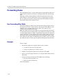
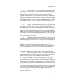
The Polycom V2IU 4300T Converged Network Appliance
The Polycom V2IU 4300T is an intelligent, all-in-one networking solution for
enterprises and service providers. It reduces costs by simplifying the
deployment, management and security of converged voice, video and data
networks. The Polycom V2IU 4300T provides the following important
functions for converged networks:
T1 Wide Area Network (WAN) Access Router
The Polycom V2IU 4300T provides an integrated T1 CSU/DSU for small and
medium office connectivity.
Security
A stateful packet inspection firewall is used in combination with a VoIP
application layer gateway to provide comprehensive “media-aware” security.
The Polycom V2IU 4300T also supports IPSec for secure site-to-site
networking.
VoIP
The Polycom V2IU 4300T resolves NAT/FW traversal problems for SIP,
MGCP and H.323 traffic. It allows a single public IP address to be used for
multiple VoIP clients.
Quality of Service
The Polycom V2IU 4300T maximizes WAN link utilization while optimizing
voice quality using prioritization and shaping.
1-1
User Guide V2IU 4300T Converged Network Appliance
Call Quality Monitoring
Passive call quality monitoring for each SIP or MGCP voice call includes
statistics needed to enforce SLAs and resolve networking problems that
negatively affect call quality.
Future-proof Scalability
The Polycom V2IU 4300T is a powerful, flexible platform that can be deployed
initially as a low-cost WAN access router and then licensed through software
for more advanced VoIP features and increased call performance. It is the
ideal platform for service providers offering DIA, hosted VoIP and managed
security services or enterprises migrating to converged voice and data
networks.
Feature Summary
•
VoIP
— SIP, MGCP (for voice) and H.323 (for video) application layer gateway
enables a single public IP address to be used for multiple VoIP
endpoints
•
QoS
— Class based queuing/prioritization
— Diffserv marking and policing
— Traffic shaping
— VoIP call admission control prevents oversubscription of priority
queue
•
Security
— Stateful packet inspection firewall
— VoIP aware firewall dynamically provisions and closes UDP ports
used for VoIP calls
— IPSec: 3DES, SHA-1
— NAT/PAT server hides enterprise LAN topology
•
Passive Call Quality Monitoring
— Per call statistics include mean opinion score (average and minimum),
jitter, latency, packet loss and much more
— Alarms for poor MOS scores
— Active call count indicators
1-2
Introduction
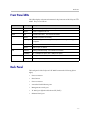
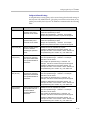
Front Panel LEDs
The LEDs display real-time information for key functions of the Polycom V2IU
4300T. They are as follows:
LED Label
Activity
Description
Power
Off
Power switch off (or no power from wall)
Green
Power is supplied to the unit
Off
Self-tests have failed. The unit has not booted.
Green
Self-tests completed successfully
Flashing
Indicates configuration is being written to permanent storage or an upgrade is
in progress
Off
The T1 is in an alarm state and not synchronized
Green
T1/E1 in-sync, no alarms
Link/Act
Flashing indicates activity. On indicates a connection
100Mbps
On = 100Mbps link speed, Off = 10Mbps link speed
Link/Act
Flashing indicates activity. On indicates a connection
100Mbps
On = 100Mbps link speed, Off = 10Mbps link speed
Status
T1/E1
LAN
Ethernet WAN
Back Panel
The back panel of the Polycom V2IU 4300T contains the following (left to
right):
•
Power connector
•
Erase button
•
Power connector
•
4 switched LAN Ethernet ports
•
Management console port
•
T1 WAN port (RJ-48 with built-in CSU/DSU)
•
Ethernet WAN port
1-3
User Guide V2IU 4300T Converged Network Appliance
Power Connector
The Polycom V2IU 4300T comes with an AC power cord and power adapter
for connecting to this port. Little force is necessary when the plug is properly
positioned.
Erase Button
To erase any custom configuration and restore the Polycom V2IU 4300T to its
factory default state depress the erase button once and press again before 2
seconds expires.
Caution
Using the Erase button as outlined above means any configuration made to the
Polycom V2IU 4300T will be lost. Additionally the VoIP ALG registration code must
be re-entered in the Polycom V2IU 4300T as covered in System Diagnostics.
Erasing the configuration means that IP phones installed behind the Polycom V2IU
4300T will not work and Internet connectivity or network access for PCs will be
down until the system is reconfigured.
Management console port
This port is used to establish a local console session with the Polycom V2IU
4300T using a VT100 terminal or emulation program. The cable required is a
straight-through 8-wire cable. The serial port uses a baud rate of 9600, 8 data
bits, 1 stop bit and no parity.
This port is used for debug or local diagnostic purposes only. Primary
configuration of the Polycom V2IU 4300T is performed from a web browser as
covered in Chapter 3.
T1/E1 WAN port
The T1 WAN interface with the following features:
•
Fully integrated CSU/DSU
•
T1 support
•
Fractional T1 support
•
Layer 2 protocol support for: HDLC, Cisco HDLC (cHDLC), PPP, Frame
Relay
•
On-board RJ-48 connector for easy direct connection
•
T1/E1 framer and transceiver
— B8ZS/HDB3 zero suppression
— Response to Inband Loop codes
— Manual payload loop through the GUI
1-4
Introduction
•
External transmit clock input and receive clock output headers
•
Timing: internal or external (loop times from the network)
•
Provides long haul CSU or short haul DSU signaling
•
Meets FCC part 68 protection requirements
The WAN port is used for connection to a data T1 line. The device at the far
end of the line is a router or other device expecting TCP/IP data. Individual
DS-0 channels on the T1 are not used to carry uncompressed voice.
Ethernet WAN port
The Ethernet 10/100 Mbps port on the Polycom V2IU 4300T can be used as a
WAN interface as an alternative to the T1 interface. This port is typically used
when connecting the Polycom V2IU 4300T to an existing T1/E1 WAN router,
cable or xDSL modem.
1-5
User Guide V2IU 4300T Converged Network Appliance
1-6
2
Getting Started
Physical Installation
The Polycom V2IU 4300T is designed for desktop, rack or wall-mount
installation. Please observe the following guidelines when installing the
system:
•
Never assume that the AC cord is disconnected from a power source.
Always check first.
•
Always connect the AC power cord to a properly grounded AC outlet to
avoid damage to the system or injury.
Ensure that the physical location of the installation has adequate air circulation
and meets the minimum operating conditions as provided in the
environmental specifications for the system.
Warning
Secure the power supply using a fastener or nearby shelf so that it does not hang
from the power connector.
Desktop Installation
1. Remove the Polycom V2IU 4300T and accessories from the shipping
container.
2. Place the Polycom V2IU 4300T on a flat, dry surface such as a desktop,
shelf or tray.
3. Connect the power and network cables to the appropriate ports on the
back of the system.
Caution
To reduce the risk of fire, use only 26 AWG or larger wire (e.g. 24, 22, 20, etc.) to
connect the T1 port on your unit to an RJ-45 jack.
2-1
User Guide V2IU 4300T Converged Network Appliance
Wall-Mount Installation
The Polycom V2IU 4300T can be wall-mounted using the two mounting
brackets on the bottom of the appliance. We recommend using two round or
pan head screws.
Install two screws 4 14/16” horizontally apart on a wall or other vertical
surface. The screws should protrude from the wall so that you can fit the
appliance between the head of the screw and the wall.
1. If you install the screws in drywall use hollow wall anchors to ensure that
the unit does not pull from the wall due to prolonged strain from the
cable and power connectors.
2. Remove the Polycom V2IU 4300T and accessories from the shipping
container.
3. Hang the Polycom V2IU 4300T on the wall.
4. Connect the power and network cables to the appropriate ports on the
back of the system.
Warning
Secure the power supply using a fastener or nearby shelf so that it does not hang
from the power connector.
Caution
To reduce the risk of fire, use only 26 AWG or larger wire (e.g. 24, 22, 20, etc.) to
connect the T1 port on your unit to an RJ-45 jack.
Administration of the Polycom V2IU 4300T
The Polycom V2IU 4300T is configured using a web browser such as Internet
Explorer or Netscape Navigator. The Polycom V2IU 4300T is shipped with a
pre-configured IP address for its LAN port of 192.168.1.1. To connect to the
Polycom V2IU 4300T, do the following:
1. Connect a PC using an IP address of 192.168.1.2 and subnet mask of
255.255.255.0 to LAN port 4 of the Polycom V2IU 4300T.
2. Launch a web browser on the PC and enter the URL string: 192.168.1.1.
Press Return. The initial Polycom V2IU 4300T main configuration menu
appears.
2-2
Getting Started
3. Select the Network link - enter the username root and the password
default to log into the system.
Note
For secure management of your network, be sure to change the default userid and
password as described under Change the Administration Password.
4. Continue to configure the system using the information provided in
Chapter 3.
2-3
User Guide V2IU 4300T Converged Network Appliance
2-4
3
Configuring the Polycom V2IU 4300T
The Polycom V2IU 4300T is a flexible, easy to use converged network
appliance that provides many critical networking functions for IP based voice,
video and data. It can be installed in several different topologies:
•
At the customer premise for IP Centrex and hosted video applications
•
At the station side of enterprise IP PBXs
•
At the trunk side of enterprise IP PBXs
•
At the public/private IP address boundary for enterprise video
applications
Most users will follow the steps provided in the “Configuring The Systems
Settings” section of this manual to initially connect the Polycom V2IU 4300T
into their IP network. The remainder of the configuration can be different
based on the application, VoIP topology and presence of other networking
equipment such as firewalls or DHCP servers. In general, however, the steps
used to configure the Polycom V2IU 4300T are:
Step
Task
1
System configuration
2
VoIP configuration
3
Data networking configuration
4
Firewall configuration
5
Traffic management configuration
Some of the steps are optional depending on your particular application. We
have provided configuration guidelines below for each of the application
types supported by the Polycom V2IU 4300T.
3-1
User Guide V2IU 4300T Converged Network Appliance
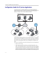
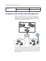
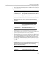
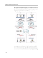
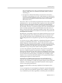
Configuration Guide For IP Centrex Applications
A typical Polycom V2IU 4300T installation for an IP Centrex application
requires no external router or firewall. The Polycom V2IU 4300T WAN port is
connected directly to the T1/E1 line and the LAN port(s) are connected
directly to enterprise devices and/or Ethernet switches.
VoIP Operations Center
Softswitch
Application Server
NMS
T1
Gateway
PSTN
PSTN
Enterprise
Enterprise
T1/FT1
4300T
T1/FT1
4300T
Gateway
EM003
VoIP signaling is performed in the service provider network via a softswitch
and the Polycom V2IU 4300T acts as a proxy for the voice devices installed in
the enterprise LAN. In this configuration a single public IP address is used to
proxy for all of the IP phones and to route to multiple PC’s installed on the
LAN.
The Polycom V2IU 4300T performs the following functions in this application:
3-2
•
WAN/LAN IP routing.
•
Traffic shaping and priority queuing to guarantee high quality voice
traffic. These mechanisms protect voice and data traffic from contending
for the same network resources to guarantee low latency and the highest
call quality possible for VoIP traffic. At the same time they ensure the best
utilization of WAN bandwidth by enabling data traffic to burst up to full
line rate in the absence of voice calls. Precedence is automatically given to
Configuring the Polycom V2IU 4300T
traffic coming from IP phones and other devices using the Polycom V2IU
4300T’s Application Layer Gateway function.
•
NAT/PAT translation for IP phones and PC’s. This allows a single public
IP address to be used on the WAN link to represent all of the private IP
addresses assigned to the LAN IP phones and PC’s.
•
Static NAT entries. This enables the customer to use a WAN public IP
address for data servers (web, mail, ftp, etc.) connected behind the
Polycom V2IU 4300T. These servers can then be configured with private
IP addresses for additional security.
•
A “VoIP” aware firewall. A full Layer 7 gateway for voice traffic and a
stateful packet inspection firewall for data traffic.
•
Call Admission Control (CAC). CAC uses a deterministic algorithm to
decide when there are insufficient network resources available to
adequately support new calls and then return the equivalent of a “fast
busy” to new call requests.
•
DHCP server and TFTP relay. These features are used to simplify and
expedite the IP configuration of phones and PC’s. This also includes VoIP
signaling gateway information (MGCP, SIP, and H.323).
•
Call quality monitoring (using MOS, jitter, latency, packet loss and much
more) and test tools.
Configuration Outline
Task
Subtask
Configure For IP Centrex
Application?
System Configuration
configure LAN/WAN interface
Yes
set ethernet link rate
Optional
enable the DHCP server
Optional but recommended
configure SNMP
Optional
enable the VoIP ALG
Yes
configure a VoIP subnet route
Optional
dynamic NAT
Optional but recommended
static NAT
Optional
static IP routing
Optional
enable the data firewall
Yes
configure basic settings
Optional
configure advanced settings
Optional
VoIP Configuration
Data Networking Configuration
Firewall Configuration
3-3
User Guide V2IU 4300T Converged Network Appliance
Traffic Management
Configuration
enable traffic shaping
Yes
enable Call Admission Control
Optional
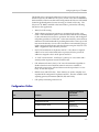
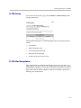
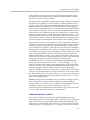
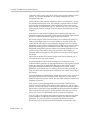
Configuration Guide For Station Side IP PBX Applications
Most private enterprise VoIP networks use an IP PBX at the corporate
headquarters location to provide voice switching between headquarters,
branch offices and the PSTN. The Polycom V2IU 4300T is used in these
environments to securely connect branch office employees to the IP PBX
installed in the corporate headquarters location.
Headquarters
IP PBX
4300T
T1
PSTN
Branch Office
Branch Office
T1/FT1
4300T
T1/FT1
4300T
Gateway
EM004
The installation of an Polycom V2IU 4300T on the station side of an enterprise
IP PBX is very similar to the IP Centrex application above. The branch office
is connected to the corporate network using a private T1/E1 link connected
directly to the WAN port of the Polycom V2IU 4300T. The LAN port(s) of the
Polycom V2IU 4300T are connected directly to enterprise devices and/or
Ethernet switches.
3-4
Configuring the Polycom V2IU 4300T
The IP PBX in the corporate headquarters location performs VoIP signaling
and the Polycom V2IU 4300T acts as a proxy for the voice devices installed at
the branch office. Please note that in the configuration the Polycom V2IU 4300T
located at the Headquarters location is acting as a WAN router only. The
Polycom V2IU 4300Ts installed at the brand offices perform the following
functions in this application:
•
WAN/LAN IP routing.
•
Traffic shaping and priority queuing to guarantee high quality voice
traffic. These mechanisms protect voice and data traffic from contending
for the same network resources to guarantee low latency and the highest
call quality possible for VoIP traffic. At the same time they ensure the best
utilization of WAN bandwidth by enabling data traffic to burst up to full
line rate in the absence of voice calls. Precedence is automatically given to
traffic coming from IP phones and other devices using the Polycom V2IU
4300T’s Application Layer Gateway function.
•
NAT/PAT translation for IP phones and PC’s. This allows a single IP
address to be used on the WAN link to represent all of the private IP
addresses assigned to the LAN IP phones and PC’s.
•
A “VoIP” aware firewall. A full layer 7 gateway for voice traffic and a
stateful packet inspection firewall for data traffic.
•
Call Admission Control (CAC). CAC uses a deterministic algorithm to
decide when there are insufficient network resources available to
adequately support new calls and then return the equivalent of a “fast
busy” to new call requests.
•
DHCP server and TFTP relay. These features are used to simplify and
expedite the IP configuration of phones and PC’s. This also includes VoIP
signaling gateway information (MGCP, SIP, and H.323).
•
Call quality monitoring and test tools.
Configuration Outline
Task
Subtask
Configure For Station
Side IP PBX
Application?
System Configuration
configure LAN/WAN interface
Yes
set ethernet link rate
Optional
enable the DHCP server
Optional but
recommended
configure SNMP
Optional
enable the VoIP ALG
Yes
VoIP Configuration
3-5
User Guide V2IU 4300T Converged Network Appliance
Data Networking Configuration
Firewall Configuration
Traffic Management
Configuration
configure a VoIP subnet route
Optional
dynamic NAT
Optional but
recommended
static NAT
Optional
static IP routing
Optional
enable the data firewall
Yes
configure basic settings
Optional
configure advanced settings
Optional
enable traffic shaping
Yes
enable Call Admission Control
Optional
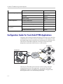
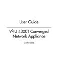
Configuration Guide For Trunk Side IP PBX Applications
Companies with existing IP-based WAN links for inter-office voice and data
communications can use the Polycom V2IU 4300T as a traffic shaper to meet
the stringent jitter, latency and packet loss requirements for toll quality voice.
The Polycom V2IU 4300T is deployed at the edge of the WAN in both
headquarters and branch office locations, as shown below.
Branch Office
4300T
Headquarters
IP PBX
T1/E1
IP PBX
4300T
Frame Relay
Or
IP Network
Branch Office
T1/E1
4300T
IP PBX
EM005
The Polycom V2IU 4300T performs WAN/LAN IP routing and traffic
management functions in this application. In particular, it provides
prioritization to ensure voice packets are not delayed or dropped while
allowing data traffic to use all remaining bandwidth.
3-6
Configuring the Polycom V2IU 4300T
Configuration Outline
Task
Subtask
Configure For Trunk Side IP
PBX Application?
System Configuration
configure LAN/WAN interface
Yes
set ethernet link rate
Optional
enable the DHCP server
Not required
configure SNMP
Optional
enable the VoIP ALG
Not required
configure a VoIP subnet route
Not required
dynamic NAT
Not required
static NAT
Not required
static IP routing
Not required
enable the data firewall
Not required
configure basic settings
Not required
configure advanced settings
Not required
enable traffic shaping
Yes
enable Call Admission
Control
Not required
VoIP Configuration
Data Networking
Configuration
Firewall Configuration
Traffic Management
Configuration
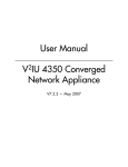
Configuration Guide For Hosted Video Applications
A typical Polycom V2IU 4300T installation for hosted video applications is
depicted in the diagram below. In this scenario, the Polycom V2IU 4300Ts are
used to connect all of the video endpoints to the Gatekeeper. The video
3-7
User Guide V2IU 4300T Converged Network Appliance
endpoints should be configured to point to the LAN address of the Polycom
V2IU 4300T as the Gatekeeper and the Polycom V2IU 4300T will proxy RAS
and call setup messages to the Gatekeeper
Service Provider
ISDN,
PSTN Network
PSTN
H.323
Gatekeeper
NMS
Softswitch
Gateway
MCU
5300-S
Aggregation Router
Hotspot
NAT/Firewall
Public IP
Network
PSTN
SIP Voice
User
T-1/E-1
Company A
NxT-1/E-1
Company B
Aggregation
Router
4300T
5300-E
4300T
H.323 Video
Endpoint
Gateway
V500
IP
Phone
Laptop
IP
Phone
H.323 Video
Endpoint
EM008B
The Polycom V2IU 4300T is installed at the customer premises and is used as a
demarcation point for the video service by providing the following functions:
3-8
•
WAN/LAN IP routing.
•
Traffic shaping and priority queuing to guarantee high quality video
traffic. These mechanisms protect video and data traffic from contending
for the same network resources to guarantee low latency and the highest
call quality possible for voice and video traffic. At the same time they
Configuring the Polycom V2IU 4300T
ensure the best utilization of WAN bandwidth by enabling data traffic to
burst up to full line rate in the absence of video calls. Precedence is
automatically given to traffic coming from video endpoints and other
devices using the Polycom V2IU 4300T’s Application Layer Gateway
function.
•
Video NAT/PAT translation for video endpoints and PC’s. This allows a
single IP address to be used on the WAN link to represent all of the private
IP addresses assigned to the LAN video endpoints and PC’s.
•
A video aware firewall. A full layer 7 gateway for video traffic and a
stateful packet inspection firewall for data traffic
•
Call Admission Control (CAC). CAC uses a deterministic algorithm to
decide when there are insufficient network resources available to
adequately support new video calls and then return the equivalent of a
“fast busy” to new call requests.
Task
Subtask
Configure For Hosted
Video Applications?
System Configuration
configure LAN/WAN interface
Yes
set ethernet link rate
Optional
enable the DHCP server
Optional
configure SNMP
Optional
enable the VoIP ALG
Yes
configure a VoIP subnet route
Optional
dynamic NAT
Optional but recommended
static NAT
Optional
static IP routing
Optional
enable the data firewall
Yes
configure basic settings
Optional
configure advanced settings
Optional
enable traffic shaping
Yes
enable Call Admission Control
Optional
VoIP Configuration
Data Networking Configuration
Firewall Configuration
Traffic Management
Configuration
3-9
User Guide V2IU 4300T Converged Network Appliance
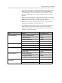
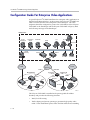
Configuration Guide For Enterprise Video Applications
A typical Polycom V2IU 4300T installation for enterprise video applications is
depicted in the diagram below. In this scenario, the Polycom V2IU 4300Ts are
used to connect all of the video endpoints to the Gatekeeper. The video
endpoints should be configured to point to the LAN address of the Polycom
V2IU 4300T as the Gatekeeper and the Polycom V2IU 4300T will proxy RAS
and call setup messages to the Gatekeeper.
Headquarters
PC
H.323
Gatekeeper
Application
Server
Softswitch
PC
NMS
PC
IP Phone
PSTN
Gateway
5300-S
5300-E
IP Phone
IP Phone
Aggregation Router
IP
Network
PSTN
T-1/E-1
Branch Office
PSTN
NxT-1/E-1
Aggregation
Router
Company B
4300T
5300-E
4300T
Gateway
H.323
H.323
Endpoint
Gateway
PC
Laptop
IP Phone
IP Phone
EM009A
The Polycom V2IU 4300T is installed at the private/public IP address
boundary and provides the following functions:
3 - 10
•
WAN/LAN IP routing.
•
Traffic shaping and priority queuing to guarantee high quality video
traffic. These mechanisms protect video and data traffic from contending
Configuring the Polycom V2IU 4300T
for the same network resources to guarantee low latency and the highest
call quality possible for voice and video traffic. At the same time they
ensure the best utilization of WAN bandwidth by enabling data traffic to
burst up to full line rate in the absence of video calls. Precedence is
automatically given to traffic coming from video endpoints and other
devices using the 4300T’s Application Layer Gateway function.
•
Video NAT/PAT translation for video endpoints and PC’s. This allows a
single IP address to be used on the WAN link to represent all of the private
IP addresses assigned to the LAN video endpoints and PC’s.
•
A video aware firewall. A full layer 7 gateway for video traffic and a
stateful packet inspection firewall for data traffic
•
Call Admission Control (CAC). CAC uses a deterministic algorithm to
decide when there are insufficient network resources available to
adequately support new video calls and then return the equivalent of a
“fast busy” to new call requests.
Task
Subtask
Configure For Hosted
Video Applications?
System Configuration
configure LAN/WAN interface
Yes
set ethernet link rate
Optional
enable the DHCP server
Optional
configure SNMP
Optional
enable the VoIP ALG
Yes
configure a VoIP subnet route
Optional
dynamic NAT
Optional but recommended
static NAT
Optional
static IP routing
Optional
enable the data firewall
Yes
configure basic settings
Optional
configure advanced settings
Optional
enable traffic shaping
Yes
enable Call Admission Control
Optional
VoIP Configuration
Data Networking Configuration
Firewall Configuration
Traffic Management
Configuration
3 - 11
User Guide V2IU 4300T Converged Network Appliance
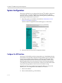
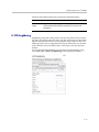
System Configuration
This section explains how to configure the Polycom V2IU 4300T to function in
your IP network. You will configure the T1/E1 WAN interface, Ethernet
interfaces, network addresses, DNS settings, default gateway, SNMP settings
and change the administrative password.
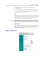
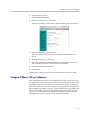
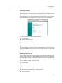
1. Physically connect to the 4300T as described in Administration of the
Polycom V2IU 4300T on page 2-2.
A browser-based configuration GUI should appear, as shown here.
2. Select the Network entry in the Configuration Menu.
Configure the LAN Interface
The Polycom V2IU 4300T provides an integrated 4 port 10/100 Mbps ethernet
switch that can be optionally configured to support 802.1q VLANs. Integrated
VLAN support simplifies the integration of the Polycom V2IU 4300T with
existing VLAN-based networks. The Polycom V2IU 4300T is able to receive
802.1q-tagged packets from a downstream VLAN switch and appropriately
route and process them per its firewall rules. Packets received from the WAN
are placed in the appropriate VLAN based on IP address routing.
By default VLANs are not enabled and a single IP address is used for all 4
ethernet ports. The configuration of this address is as follows:
1. Enter the IP Address.
2. Enter the Subnet Mask (e.g. 255.255.255.0).
3 - 12
Configuring the Polycom V2IU 4300T
3. Press Submit.
Configuring VLANs in the Polycom V2IU 4300T
As depicted in the diagram below, VLANs are used to connect the Polycom
V2IU 4300T to an Ethernet switch that has been configured to use VLANs.
VLANid 1/2
VLANid 1/3
VLAN
Switch
4300T
VLANid 1/2/3
VLANid 1/2/3
(VLANid 16)
P1
P2
P3
P4
WAN
802.1
EM006
Typically, all VoIP devices are placed in the same VLAN while data devices
are placed in a different VLAN. This is to ensure priority treatment of the VoIP
traffic on the LAN. Note that the Polycom V2IU 4300T does not require
VLANs to prioritize VoIP traffic; prioritization is determined by the VOS
Application Layer Gateway, regardless of VLAN. Some important notes
about VLANs:
•
A physical LAN port will operate in either 802.1 or 802.1q mode, not both
simultaneously
•
The Polycom V2IU 4300T supports up to 16 VLANs
•
A unique IP Subnet is assigned to each VLAN
•
You can associate one or more VLANs to each LAN port operating in
802.1q mode
•
Traffic within a VLAN is switched among all ports with membership
•
Traffic between VLANs is routed by the Polycom V2IU 4300T
•
The Polycom V2IU 4300T ALG can only be assigned to one VLAN id
— Only ALG traffic is prioritized over the WAN
— Other non-VoIP traffic in the same VLAN will not receive priority
treatment
•
A DHCP server can be enabled/disabled per VLAN
•
Cisco Discovery Protocol is not supported
3 - 13
User Guide V2IU 4300T Converged Network Appliance
•
802.1p is not currently supported
1. Select the Network link.
2. Select Enable VLAN support.
3. Press Submit.
Caution
Be careful when changing a port from 802.1 to 802.1q mode. Any 802.1 devices
connected to that port (such as your management PC!) will loose access to the
Polycom V2IU 4300T. Port 4 is only able to receive 802.1 frames, so a PC can
always be connected to this port if the configuration of the other ports is unknown.
4. Select System.
5. Select VLAN Configuration.
6. Adjust LAN Port Membership drop-down boxes to specify 802.1 or
802.1q mode, as desired. Press Modify.
If changing modes, the radio-buttons or checkboxes will change from one
style to the other.
7. Under Add and configure a new VLAN enter a new VLAN ID, the
Polycom V2IU 4300T’s IP address within this VLAN, and the Network
Mask. Press Add.
A new VLAN entry will be added to the VLAN Configuration above.
8. Depending on the mode of a physical port, assign it to one or more
VLANs:
3 - 14
Configuring the Polycom V2IU 4300T
— 802.1 mode: Assign the port to any ONE VLAN.
— 802.1q mode: Assign the port to any number of VLANs
Perform steps 1 through 6 above for each VLAN you wish to create.
Modify an Existing VLAN Configuration
1. Select the Network link.
2. Select VLAN Settings.
3. Change the desired settings.
4. Press the Modify to modify the VLAN. The Reset button will restore the
input area being modified to its previous value.
Delete an Existing VLAN Configuration
1. Select the Network link.
2. Select VLAN Settings.
3. Press the trash can icon next to the VLAN you wish to delete.
3 - 15
User Guide V2IU 4300T Converged Network Appliance
Assign the Polycom V2IU 4300T’s ALG to your Priority VLAN
Once you have completed your VLAN configuration you must assign the
Polycom V2IU 4300T ALG to the VLAN containing your VoIP phones.
1. Select the VoIP ALG from the main configuration menu.
2. Use the drop down menu to assign the ALG to the VLAN ID containing
your VoIP phones.
3. Press Submit.
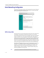
Configure the WAN Interface
The 10/100 Ethernet WAN port is configured as follows:
1. Select ADSL-PPPoE if you want to connect to Internet using ADSL and
your ISP has given PPPoE username and password. Press Submit. You
will be prompted to enter username and password, enter these and press
Submit again.
2. Select DHCP if you want to get WAN side IP address using DHCP server
available in WAN side of the network. Press Submit.
3. Select Static IP address if you want to manually assign the IP address
configuration to the ethernet WAN interface.
4. Enter the IP Address.
5. Enter the Subnet Mask (e.g. 255.255.255.0).
3 - 16
Configuring the Polycom V2IU 4300T
6. Enter the Default Gateway. This is usually the upstream router’s IP
address. Packets destined for IP networks not known to the Polycom
V2IU 4300T are forwarded to the default gateway for handling.
7. Enter the Primary DNS Server. The DNS server is used by the Polycom
V2IU 4300T to resolve domain names to IP addresses. The value entered
into this field is provided to IP devices that use the Polycom V2IU 4300T
as a DHCP server. The Polycom V2IU 4300T VoIP ALG also uses it if
domain names are used instead of IP addresses to identify signaling
and/or TFTP servers (see the section entitled “Configuring the VoIP
ALG” for more details).
8. Enter the Secondary DNS Server. This server will be used in the event
that the primary DNS server is not reachable.
9. Press Submit.
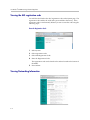
To enable the T1 interface:
1. Select Network.
2. Select the T1 radio button.
3. Select Submit.
To configure the T1 parameters:
1. Select Network.
2. Select the T1 link next to the radio button to proceed to the T1
Configuration page.
The T1 Configuration menu will display, as shown here.
3 - 17
User Guide V2IU 4300T Converged Network Appliance
The Polycom V2IU 4300T supports a wide range of T1/E1 Layer 2
configuration parameters. The specific values you will need must be supplied
by the WAN provider.
Each of the Polycom V2IU 4300T’s configurable parameters are described
below.
Protocol
Display and set the T1 Layer 2 protocol. Supported protocols are:
•
HDLC
•
Cisco HDLC
•
PPP
•
ANSI (Frame Relay)
•
CCITT (Frame Relay)
1. Select the desired T1 protocol.
2. Press Submit.
Frame Relay Mode and DLCI
When the Protocol is one of ANSI or CCITT, then additional Frame Relay
configuration parameters are required.
The Frame Relay Mode is usually set to DTE for the customer premises.
The Frame Relay DLCI is set by the WAN provider and identifies the far-end
device across the Frame Relay network. This DLCI can also be used to carry
voice traffic only by enabling the Secondary DLCI for data.
Most installations will use a single DLCI for both voice and data traffic.
However, in instances where the network will provide a different quality of
service based on DLCI number it is desirable to place all voice traffic on one
DLCI and then configure a second DLCI for data. In this case, the Secondary
DLCI is configured as follows:
1. Select Network.
3 - 18
Configuring the Polycom V2IU 4300T
2. Select the T1 link next to the radio button to proceed to the T1
configuration page.
3. Select Enable in the Frame Relay Secondary Settings section of the page.
4. Enter the Secondary DLCI, IP Address, Network Mask and Gateway for
the data traffic using the Secondary DLCI.
Timing
Display and set the clock timing source for the T1/E1 interface. The timing can
be either derived from the network (External) or provided to the T1 interface
by the V2IU (Internal). With a carrier-provided T1, the timing is usually
derived from the network (External, the default setting).
Warning
Mismatched timing modes can result in WAN connectivity but with intermittent data
loss.
Payload Loopback
Display and set the loopback setting. During T1 line testing the local interface
can be set to Loopback to allow the network provider to verify connectivity
and line quality. For normal operation the setting should always be No
Loopback (the default setting).
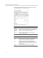
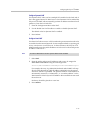
Configure the DHCP Server
3 - 19
User Guide V2IU 4300T Converged Network Appliance
The Polycom V2IU 4300T can act as a DHCP server granting IP addresses to
PCs, workstations, servers or voice devices (IP phones, IADs or softphones)
connected to its LAN interfaces. DHCP is a protocol that enables IP devices to
obtain temporary or permanent IP addresses (out of a pool) from centrally
administered servers.
The user can configure blocks of IP addresses, a default gateway, DNS servers,
NTP server address, Time offset from NTP value, WINS address and
TFTP/FTP server name that can be served to the requesting IP devices.
In addition the Polycom V2IU 4300T will provide its LAN IP address in DHCP
user options 150 and 151 for use by IP phones. Some IP phones use these
values for configuration of their TFTP server and MGCP control server
addresses.
Note
The DHCP server in the Polycom V2IU 4300T should not be used if a DHCP server
already exists in the same subnet as the Polycom V2IU 4300T. Also, it is
recommended that you assign static IP addresses for common-access devices
such as network printers or fax machines.
You can also enable or disable the Polycom V2IU 4300T DHCP server on a per
VLAN basis.
1. Select DHCP Server.
2. If you are using VLANs select the desired VLAN ID from the drop down
menu.
3. The default value for the DHCP server is disabled. Click the top
checkbox to enable or disable the internal DHCP server (default is
disabled). If you are using VLANs select the desired VLAN ID.
4. Enter the Lease Duration.
The lease duration is the amount of time in days that an IP device may use
an assigned IP address before requesting that it be renewed. The default
value is 7 days and the valid range of input is 1 to 30 days.
5. Enter the Subnet Mask.
This is the subnet mask that will be sent via DHCP to the requesting IP
devices.
6. Enter the DHCP IP Addresses.
This is the pool of IP addresses that will be provided to the requesting IP
devices. You can enter both individual IP addresses or a range of
addresses using the following format:
192.168.1.2 (single address)
192.168.1.4-10 (address range 192.168.1.4 through 192.168.1.10)
Note
3 - 20
The range format can only be used for class C addresses (those with a subnet
mask of 255.255.255.0).
Configuring the Polycom V2IU 4300T
7. Enter the Time Offset (DHCP user option 2).
8. Set the time offset in hours from UTC for your local location. This value
is optional; if supplied, it will be delivered to clients.
9. Enter the NTP Server Address (DHCP user option 42).
This is the IP address of a Network Time Server. This value is optional; if
supplied, it will be delivered to clients.
10. Enter the WINS Address.
Note
If you are not using WINS leave this field blank.
The Windows Internal Naming Service (WINS) is a service that keeps a
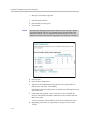
database of computer name-to-IP address mappings so that computer
names used in Windows environments can be mapped to IP addresses.
The WINS Address is the IP address of the WINS server in your network.
This value will be delivered to clients.
1. Enter the TFTP/FTP Server Name (DHCP user option 66).
Some IP phones use this setting to locate the TFTP or FTP servers which
contain the phone software image used during boot. By default this
option is the same as the TFTP server on the VoIP ALG page.
2. Primary and Secondary DNS
The primary and secondary DNS values come from those set under the
WAN interface configuration, see Configure the WAN interface. These
values will be delivered to clients.
3. Default Gateway
The default gateway is automatically set to the Polycom V2IU 4300T’s
LAN address, see Configure the LAN interface. This value will be
delivered to clients.
4. Press Submit.
Delete a DHCP IP Address
1. Select DHCP Server.
3 - 21
User Guide V2IU 4300T Converged Network Appliance
2. To delete an IP address or a range of IP addresses highlight an entry or
range of entries in the DHCP IP Addresses list and press the Delete key
on your keyboard.
3. Press Submit.
Disable The DHCP Server
1. Select DHCP Server.
2. Uncheck the Enable DHCP Server checkbox.
3. Press Submit.
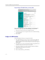
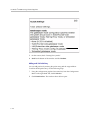
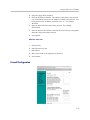
Configure Hostname, SNMP and Remote Logging
The Polycom V2IU 4300T can be managed remotely by an SNMP network
management system such as HP Openview. The Polycom V2IU 4300T
supports SNMPv1 or SNMPv3 and MIB-II (RFC1213). All MIB-II variables are
read only. The MIB variables sysContact and sysLocation are set by the web
GUI.
3 - 22
Configuring the Polycom V2IU 4300T
Messages generated by the Polycom V2IU 4300T can be sent to a remote log
server.
The configuration screen is reached through the Configuration Menu:
1. Select System.
2. Select System Overview.
3. Select Services Configuration.
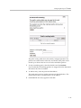
Configure SNMP
1. Select the Enable SNMP v1 or v3 checkbox. If using SNMPv1 enter the
Read-Only Community. If using SNMPv3 enter the User Name,
Passphrase and Security method.
2. Enter the System Location.
This is a comment string that can be used to indicate the physical location
of the Polycom V2IU 4300T. By default, no value is set.
3. Enter the System Contact.
This is the administrative contact information for the Polycom V2IU 4300T.
By default, no value is set.
4. Enter the SNMP Port.
This is the port that the Polycom V2IU 4300T uses for SNMP
communications with the network management system. The default is
161.
5. Press Submit.
Disable SNMP
1. Select System.
2. Select System Overview.
3. Select Services Configuration.
4. Uncheck the Enable SNMP checkbox.
5. Press Submit.
Configure Remote System Logging
The Polycom V2IU 4300T can be configured to log system messages to an
external syslog server.
1. Select the Enable Remote System Logging checkbox.
3 - 23
User Guide V2IU 4300T Converged Network Appliance
2. Enter the IP address of the Remote Syslog Host.
By default messages are sent to the remote host on port 514. This port can
be changed by using the syntax ADDRESS:PORT.
3. Press Submit.
Disable Remote System Logging
1. Select System.
2. Select System Overview.
3. Select Services Configuration.
4. Uncheck the Enable Remote System Logging checkbox.
5. Press Submit.
Configure a local Hostname
A locally configured hostname is useful for remote management. This name
can appear as the identifier string for the Polycom V2IU 4300T on a system
management console.
>> Enter a host name in the field provided.
Enable Mean Opinion Scoring (MOS)
The Polycom V2IU 4300T produces useful statistics on a per call basis that can
be written to syslog. These include MOS, jitter, latency, packet loss and much
more.
1. Select System.
2. Select System Overview.
3. Select Services Configuration.
4. Select Enable MOS.
Set MOS Threshold
You can define a minimum MOS value in the Polycom V2IU 4300T such that a
message will be sent to syslog when the measured MOS value drops below the
minimum. This is useful when for monitoring a particular location for call
quality problems and enables pro-active resolution of problems that
negatively affect call quality.
1. Select System.
2. Select System Overview.
3. Select Services Configuration.
3 - 24
Configuring the Polycom V2IU 4300T
4. Enter the minimum MOS threshold in the Set MOS threshold field.
5. Press Submit
Change the Administration Password
We strongly recommend that you change the default password for the root
administrative account using the following steps:
The new password must be between 6 and 20 characters in length. Any
combination of alpha and numeric characters is accepted.
Note
1. Enter the password you chose in step C again in the Confirm Password to
ensure that there were no mistakes in the initial entry.
2. Press Submit.
Read-only User
This feature works by creating a new user with read-only access to the system.
All information is displayed in a non-changeable form. Information changed
in entry boxes cannot be submitted. In fact, most Submit and OK buttons are
not visible.
Note: You must have administrator privileges and log in as an administrator
to change read-only user.
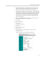
Enabling a Read-only User
To enable a read-only user, use the following steps:
1. Using the configuration graphical user interface, from the Configuration
Menu on the left-hand side, click Network.
Note: You must have administrator access and log in as an administrator
to change read-only user.
3 - 25
User Guide V2IU 4300T Converged Network Appliance
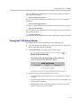
2. Scroll down to the area of the screen shown below.
3. Click changed. The following window screen appears:
Note: All open web browsers must be closed when you change between
administrative user “root” and read-only “rouser.”
4. Enter a new password. The password must be a minimum of six
characters long.
4. Re-enter the new password to confirm it.
5. Click Submit.
Now when you access the system using this user name (rouser) and password,
all fields are read-only.
Subinterfaces
The Subinterfaces feature allows a system administrator to assign additional
IP addresses to interfaces. These are sometimes referred to as aliases or
loopback interfaces. An additional address may be assigned to the system’s
WAN interface to support, for example, another management IP address.
How Subinterfaces Works
A common use for subinterfaces is forwarding a public subnet. A subinterface
may be created to support a subnet forwarded through the Polycom V2IU
4300T. When forwarding a subnet through the Polycom V2IU 4300T, it is
3 - 26
Configuring the Polycom V2IU 4300T
necessary to assign an address for this subnet to the system to act as the
subnet's gateway. To configure forwarding rules, use the Forwarding Rules
submenu under the Firewall configuration link.
When applied to the WAN/Provider interface, these addresses are protected
by the same firewall policy that is applied to the WAN/Provider address.
Several other features in the system automatically create Subinterfaces. VRRP
(if supported) and Static NAT automatically create Subinterfaces.
When viewing the Network Information page, Subinterfaces are designated in
the Interface Information section with the device name and number, separated
by a colon (for example, eth0:100).
Configuring Subinterfaces
To configure subinterfaces, use the following steps:
1. Using the configuration graphical user interface, from the Configuration
Menu on the left-hand side, click Network.
2. Click Subinterfaces. The window shown below opens.
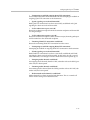
3. On this screen, complete the following information:
•
IP Address is the address to be assigned to the subinterface.
•
Netmask is the network mask to use for the address. If several addresses
are applied to an interface and these addresses are in a common network,
they must use a common subnet. The system does not support
supernetting.
•
Interface is the port where the subinterfaces will be configured.
3 - 27
User Guide V2IU 4300T Converged Network Appliance
4. When you have finished entering this information, click Add. The
following popup appears:
5. Click OK. The new subinterfaces entry appears on the Subinterfaces
window in the list area.
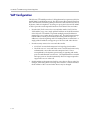
ToS Byte Setting
Since the Internet itself has no direct knowledge of how to optimize the path
for a particular application or user, the IP protocol provides a limited facility
for upper layer protocols to convey hints to the Internet Layer about how the
trade-offs should be made for the particular packet. This facility is the “Type
of Service” or ToS facility.
ToS settings allow the service provider to prioritize time sensitive traffic, such
as voice plus video to ensure minimized packet loss and delay through their
network. When providing end-to-end QOS, it is important that the voice plus
video traffic be placed in the correct queues to deliver a higher QOS than
regular traffic. Regular traffic, that is not time sensitive, can be delayed with
little or no indication to the user, while the slightest delay in voice plus video
can cause auditable differences. The ToS byte setting helps prioritize traffic
going to the WAN so a provider can prioritize the traffic correctly in its
network.
Although the ToS facility has been a part of the IP specification since the
beginning, it has been little used in the past. However, the Internet host
specification now mandates that hosts use the ToS facility. Additionally,
routing protocols (including OSPF and Integrated IS-IS) have been developed
which can compute routes separately for each type of service. These new
routing protocols make it practical for routers to consider the requested type
of service when making routing decisions.
How the ToS Byte Setting Works
For all RTP traffic (voice and video), the Polycom V2IU 4300T marks the ToS
byte in the IP header as “High Priority,” and strips (set to 0) the ToS byte for
all other traffic. Unchecking the “Enable ToS Byte Stripping” option means
that the ToS byte will not be stripped from non-RTP traffic, but will remain
unchanged.
Note: For most situations, you should leave this setting as it is. Only change it
if your provider indicates that you should do so.
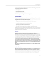
Viewing or Changing the ToS Byte Setting
To view or change the ToS byte setting, use the following steps:
3 - 28
Configuring the Polycom V2IU 4300T
1. Using the configuration graphical user interface, from the Configuration
Menu on the left-hand side, click Traffic Shaper.
2. Scroll down the area of the screen shown below.
3. For most situations, you should leave this setting as it is. Only change it if
your provider indicates that you should do so. If your provider indicates
that you need to change the ToS byte setting, that provider should also
provide the other parameters required on this screen.
4. If you have changed the values, click Submit to activate the new settings.
3 - 29
User Guide V2IU 4300T Converged Network Appliance
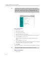
H.323 Configuration
To access the H.323 Settings page, select VoIP ALG > H.323 in the Configuration Menu.
3 - 30
Configuring the Polycom V2IU 4300T
The H.323 Settings page has the following areas:
•
Gatekeeper Mode
•
WAN/Provider-side gatekeeper mode settings
•
LAN/Subscriber-side gatekeeper mode settings
•
Embedded gatekeeper mode settings
•
LRQ Size
•
Default Alias
•
Stale Time
•
Multicast Messages
3 - 31
User Guide V2IU 4300T Converged Network Appliance
•
H.460.18 Support
•
Alias Restrictions
In the Gatekeeper mode area, select one of the following modes:
Item
Description
None
H.323 is disabled.
WAN/Provider-side
gatekeeper mode
Specifies that the system will forward all client RAS
messages to the gatekeeper. If this is selected, you must
configure the settings in the WAN/Provider-side
gatekeeper mode settings area.
LAN/Subscriber-side
gatekeeper mode
Specifies that the system will act as a gatekeeper. If this
option is selected, you must configure the settings in the
LAN/Subscriber-side gatekeeper mode settings area.
Peering-Proxy mode
Allows calls to be forwarded to other endpoints based on
the information sent from the endpoints. All the
information about routing the call must be sent as part of
the request or prefixes must be configured.
Embedded gatekeeper
mode
Provides gatekeeper functions and accepts endpoint
registrations. If this option is selected, you must configure
the settings in the Embedded gatekeeper mode settings
area.
This mode supports a maximum of 15 registered
endpoints.
If WAN/Provider-Side Gatekeeper mode is selected, you must configure the
following parameters:
3 - 32
Item
Description
WAN/Provider-side GK
address
Specifies the IP address of the gatekeeper
Modify Time-To-Live
Allows you to override the value for time-to-live returned
by the gatekeeper before forwarding the response to the
endpoint.
New Time-To-Live
Specifies how long an endpoint's registration should be
valid.
Configuring the Polycom V2IU 4300T
If LAN/Subscriber-Side Gatekeeper mode is selected, you must configure the
following parameters:
Item
Description
LAN/Subscriber-side GK
address
Enter the IP address of the gatekeeper.
Allow public IP in LCF
Select the checkbox if the gatekeeper has been deployed
with multiple outbound proxies and must decide which
proxy to use based on the IP address returned in the LCF.
This is an advanced configuration option and should
usually not be selected.
If Embedded Gatekeeper is selected, you must configure the following
parameters:
Item
Description
Time-to-Live(s)
Enter a time in seconds. This setting controls how
long an endpoint’s registration should be valid. At
the end of this period the endpoint sends another
registration request.
Prevent calls from
unregistered endpoints:
Blocks unregistered LAN-side endpoints from
making calls through the device.
In the LRQ Size area, you can limit the number of source aliases in a
forwarded LRQ message to a maximum of two to allow interoperability with
gatekeepers that cannot handle more than two source aliases.
In the Default Alias area, you can specify a default alias to be added to incoming calls without a destination message in the Q.931 Setup message. This alias
allows the embedded gatekeeper or a LAN/Subscriber-side gatekeeper to
route the call to a default endpoint. Enter a default alias and select one of the
following types:
•
E.164
•
H.323
In the Stale Time area, you can arrange to delete clients that have not sent any
registration requests for the specified interval. This area includes the
following configurable parameters:
Item
Description
Delete stale clients
Select this checkbox to enable the stale timer feature.
Stale time (m)
Specify the length of the interval in minutes.
3 - 33
User Guide V2IU 4300T Converged Network Appliance
Some RAS messages can be multicast in order to automatically detect gatekeepers. In the Multicast Messages area, you can enable listening to multicast
messages. This area includes the following configurable parameter:
Item
Description
Listen to multicast
messages
Select this checkbox to enable listening to multicast
messages.
In the H.460.18 Support area, you can configure H.460.18 support. This allows
the system to do NAT/Firewall traversal for clients behind NAT or firewall
devices. This area includes the following configurable parameters:
Item
Description
Disabled
Disables H.460.18 support.
Enabled
Enables H.460.18 support.
Keep-alive time(s)
Specifies the keep-alive time if H.460.18 support is
enabled.
In the Alias Restrictions area, you can set a limit on the number of aliases that
are allowed to register with the system. If this number is exceeded when a client tries to register, the registration is rejected. This area includes the following parameter:
Item
Description
Max Aliases
Enter the maximum number of allowed aliases. If the value is set
to 0, the maximum is not enforced.
The H.323 Settings page includes the following two buttons:
3 - 34
Item
Description
Submit
Applies the settings configured on this page.
Reset
Clears all fields and selections and allows you to enter new
information.
Configuring the Polycom V2IU 4300T
H.323 Activity
To access the H.323 Activity page, select VoIP ALG > H.323 Activity in the
Configuration Menu.
The H.323 Activity page is a read-only page that shows the following information:
•
Current time
•
WAN Gatekeeper status
•
Current payload bandwidth
•
Estimated total bandwidth
•
Activity log of recent H.323 events
H.323 Alias Manipulation
Alias manipulation is performed immediately when a message (such as an
ARQ, LRQ or a Setup) is received. Any matching pattern is replaced with the
specified string, allowing you to replace characters or strings that are hard or
impossible to dial on certain endpoints. Normal call look-up is performed
following alias manipulation.
3 - 35
User Guide V2IU 4300T Converged Network Appliance
To access the H.323 Alias Manipulation page, select VoIP ALG > H.323
>Alias Manipulation in the Configuration Menu.
This page includes the following areas:
3 - 36
Item
Description
Destination
H323-ID or
E.164 Alias
Modification
table
Lists alias manipulation rules.
Add a rule
Allows you to add new prefixes to the Prefix Routing and
Gatekeeping Neighboring table.
Item
Description
Action
Indicates whether the rule is to be added or edited.
Pattern
Specifies the pattern to be matched. See <l_link>“Regular
Expressions” on page 39 for details on valid patterns.
Index
Determines the order in which the rule is scanned in the
Destination H323-ID or E.164 Alias Modification table. To add a
rule between two rules with consecutive indexes (n and m), use
the higher index (m).
Replace
Specifies the string that will replace the matched pattern.
Rules are executed in the order in which they are listed. Use the
arrows to move entries up and down, or use the Index field to
specify where a new or edited rule falls in the list.
Configuring the Polycom V2IU 4300T
The H.323 Alias Manipulation page includes the following buttons:
Item
Description
Commit
Applies the settings configured on this page.
Reset
Clears all fields and selections and allows you to enter new
information.
H.323 Neighboring
Neighboring and prefix routing can be used to route calls based on a matching prefix in the destination alias of the call. The call decision is made following alias manipulation and acts on the modified string, similar to other call
lookup processes such as registered client look-up. Each prefix is associated
with a domain name or IP address that is used in the event that the prefix
matches.
To access the H.323 Neighboring page (formerly the Prefix Routing page),
select VoIP ALG > H.323 > Neighboring in the Configuration Menu.
3 - 37
User Guide V2IU 4300T Converged Network Appliance
This page includes the following areas:
Item
Description
Prefix Routing
and
Gatekeeper
Neighboring
table
Lists rules for forwarding incoming calls based on their dialed
alias.
Add a prefix
Allows you to add new prefixes to the Prefix Routing and
Gatekeeper Neighboring table.
Item
Description
Action
Indicates whether the rule is to be added or edited.
Prefix
Specifies the prefix pattern to be matched against the dialing
string. See <l_link>“Regular Expressions” on page 39 for details
on valid patterns.
Index
Determines the order in which the rule is scanned in the Prefix and
Gatekeeper Neighboring table. To add a rule between two rules
with consecutive indexes (n and m), use the higher index (m).
Strip
Indicates whether the matching prefix is stripped from the dialing
string.
Add
Specifies a string to be prepended to the dialing string.
Neighbor
Determines whether a location request (LRQ) is sent when this
prefix matches.
Rules are executed in the order in which they are listed. Use the
arrows to move entries up and down, or use the Index field to
specify where a new or edited rule falls in the list.
•
If enabled, the prefix becomes a neighboring statement.
•
If disabled, the incoming Q.931 Setup is forwarded to the given
address without a preceding LRQ.
This field is used for interoperability with other gatekeepers that
may not accept a Setup without a preceding LRQ.
Local Zone
Provides compatibility with remote gatekeepers that are
configured to accept LRQs only from sources that match its
configured remote zone. If a gatekeeper is configured to accept
requests only from a known source, enter the zone in this field.
Address
Specifies the IP address or domain name of the device to which
the call is to be forwarded.
The H.323 Neighboring page includes the following buttons:
3 - 38
Item
Description
Commit
Applies the settings configured on this page.
Reset
Clears all fields and selections and allows you to enter new
information.
Configuring the Polycom V2IU 4300T
Regular Expressions
Alias manipulation patterns and prefixes use regular expressions to match a
string in the destination alias. A regular expression can be a string of literal
characters to match or a set of special expressions.
Alias manipulation patterns can match a sub-string at any location and
number of times within the alias. Prefixes are always searched from the left of
the alias and cannot match a middle part or the end of the alias.
Regular expressions are listed in <l_link>Table 1 and <l_link>Table 2 lists
some example expressions.
Table 1 Regular Expressions
Symbol
Description
.
Matches any single character.
[]
Matches any single character listed between the []. For example,
[abc], [123]. If the characters are separated by a -, all characters
between the two are matching, e.g. [a-z], [0-9]
()
Matches the literal string given, e.g. (abc)
|
Matches the block on either side of the |, e.g. a|b.
?
Matches 0 or 1 of the preceding block.
*
Matches 0 or more of the preceding block.
+
Matches 1 or more of the preceding block.
\
Escapes the special meaning of the next character.
{a}
Matches exactly 'a' numbers of the preceding block.
{a,}
Matches 'a' or more of the preceding block.
{a,b}
Matches between 'a' and 'b' (inclusive) of the preceding block.
Table 2 Example Regular Expressions
Expression
Description
100
Matches the string 100.
(555)?123
Matches 555123 or 123.
(408|555)
Matches 408 or 555.
555[0-9]{3}
Matches 555 followed by exactly 3 digits.
#
Matches the character '#'.
\*
Matches the character '*'. Note that '*' by itself is a regular
expression and must therefore be escaped with a '\' to match the
character itself.
3 - 39
User Guide V2IU 4300T Converged Network Appliance
Forwarding Rules
Forwarding Rules allows a system administrator to forward data traffic for a
subnet from one interface to another, overriding the Firewall’s default drop
rules.
Allowing a subnet to be forwarded is commonly used when servers with
public addresses are placed behind the system. Configuring the network in
this way allows the system to manage and prioritize bandwidth, sharing it
between the VoIP services and the servers.
How Forwarding Rules Works
When forwarding, one address from the forwarded range of addresses must
be assigned to the rule's output interface. The Polycom V2IU 4300T uses this
address to act as a gateway router for the subnet. The address may be
assigned using the Subinterfaces page.
Note: The subnet and forwarded addresses are not protected by the firewall.
A similar method for forwarding traffic is provided by Proxy ARP. Proxy ARP
is used to bridge addresses within a single subnet range from one interface to
another. Often this is used to bridge and forward a public address to the protected side of the system without having to subnet the public address range.
Proxy ARP does not require an additional gateway address on the system for
the subnet, but does not allow port and protocol filtering for forwarded data.
Example
In this example:
•
The ISP has supplied two separate subnets to the customer:
— A small one (2 hosts) for the WAN link
— A large one (254 hosts) for a bank of servers
•
67.40.41.2 is the WAN IP address for the Polycom V2IU 4300T
•
NAT is a private IP range of 192.168.1.xxx using the WAN address for PCs
and Phones
•
On the LAN side of the Polycom V2IU 4300T are the following:
— Private IP subnet (192.168.1.xxx)
— Public IP subnet (67.40.40.xxx)
This is shown below.
3 - 40
Configuring the Polycom V2IU 4300T
Configuring Forwarding Rules
To configure address forwarding rules, use the following steps:
1.
Using the configuration graphical user interface, from the Configuration
Menu on the left-hand side, click Firewall.
2.
Click Forwarding Rules. The window shown below opens.
3 - 41
User Guide V2IU 4300T Converged Network Appliance
3.
On this screen, complete the following information:
•
IP Subnet: The subnet to be forward through the firewall from the Input
Interface to the Output Interface.
•
Netmask: The network mask to apply to the IP Subnet to create the range
of IP addresses that are forwarded through the firewall.
•
Input Interface: The interface where data is received that is destined for
the forwarded subnet (destination address(es)).
•
Output Interface: The interface where data is received that is sent from the
forwarded subnet (source address(es)).
•
Protocol: The following protocols are used:
— UDP: for the specified network, allows the specified UDP port or port
range to pass through the system
— TCP: for the specified network, allows the specified TCP port or port
range to pass through the system
3 - 42
Configuring the Polycom V2IU 4300T
— Any: for the specified network, allows all ports and protocols through
the system. No ports are required because not all protocols support
the concept of ports.
•
Port or Port Range: The port number or port range allowed through the
system when UDP or TCP are selected. A port range is specified by
separating the starting and ending ports with a colon ':' (for example,
22:80). The ports parameter is not supported when you select Any
protocol because not all protocols support the concept of ports.
4.
When you have finished entering this information, click Add.
5.
Click OK. The new forwarding entry appears on the Forwarding Rules
window in the list area.
Peering Proxy
H.323 prefixes can be used to route calls based on a matching prefix in the
destination alias of the call. Each prefix is associated with a domain name or IP
address to send the call to in case the prefix matches.
The prefixes are searched in order, that is, the first prefix is tried first, and then
the next one on the list until the system finds a matching prefix. This means
that if there are multiple matching prefixes, the first one is used.
How Peering Proxy Works
The Polycom V2IU 4300T supports the concept of an H.323 Peering Proxy. This
function provides advanced security layers or peering points within the
network where a security layer is needed. Peering Proxy allows network
providers to add internetworking connections between their “trusted”
network and an unknown network. This topology hides their trusted network
and the Stateful packet inspection Firewall provides the policies to ensure
security. You can add Peering Proxies in series with one another to push the
core H.323 networking infrastructure to meet individual security
requirements.
The illustration below shows a sample diagram with dial plan and call flow
examples. It is a snapshot of how the Peering Proxy can be deployed. Peering
Proxy however, is not limited to this specific scenario, so contact your Polycom
representative to discuss specific network requirements for full Peering Proxy
support.
3 - 43
User Guide V2IU 4300T Converged Network Appliance
Note: A minimum configuration for Peering Proxy would be for inbound only
prefixes, since there may be many endpoints to statically route calls to. There
might also be a master gatekeeper to which all endpoints are registered. In this
case, you would only need 1 prefix pointing to the master gatekeeper and let
that gatekeeper signal the other endpoints directly.
In the example above, the Polycom V2IU 4300T Peering Proxy is installed in
“Private Video Network A and B,” a peering point into this network. This
network could have additional peering points to allow topology spreading of
network resources. However, this example shows only a single point. Peering
3 - 44
Configuring the Polycom V2IU 4300T
Proxy provides an access point into this network and is responsible for the
E.164 dial plan using NANP (North American Numbering Plans or NAP’s).
The NAP’s in this case are 831 and 408.
Dial plan integrity is required to insure proper routing of prefix's. This means
that if users are to dial into your network, they could be required to enter a
“Prefix” on their V2IU with a corresponding destination IP. If the user was to
dial another user NOT destined to your network with the same beginning
prefix, the prefix configured on this V2IU would create a prefix match and the
call would route incorrectly. The call routes to the destination defined in the
prefix and not to the intended endpoint. The example shows “Private Video
Network A's Peering Proxy” with an inbound prefix defined as 8315…… Any
inbound call that matches 8315 with any 6 digits creates a prefix match and
sends the call to 10.10.11.1. Refer to “Regular Expressions” in the Info button
on the GUI interface for information on all the methods for defining prefixes.
Private Video Network A is one example of a V2IU configured in “LAN Side
Gatekeeper” mode with an ANNEX O dial method to dial “Off Net.” Internal
“On Net” endpoints registered to the LAN Side Gatekeeper will dial E.164
only. This allows any location to place calls to any location with an ANNEX O
dial plan, that is, E.164@WAN_IP or other V2IF’s deployed on the network. In
this example a Peering Proxy has been deployed to allow dialing ingress and
egress to the Public Internet. At each V2IU location required to egress, the
Public Internet requires a “Prefix” to be configured. This allows that location's
endpoint to dial “Off Net” to the Public Internet. This prefix can be configured
to any digit and may be part of the externally dialed E.164 in the
E.164@WAN_IP, that is, to reach site A by dialing [email protected]
where the prefix is defined as 415* or 415……. In this example, a “9” was
chosen. The prefix is then mapped to the LAN interface of the Peering Proxy
10.10.11.1. The dial string is now [email protected] and a strip rule for
the prefix is applied. This is needed to route the call at the destination
correctly. If the Site C V2IU does not strip the “9”, the destination V2IU fails the
call with a “No Registered Client” message (call failures can be viewed under
the “H323 Activity” page in the GUI), since the “9” becomes part of the E.164.
If you choose a prefix that matches the destination E.164, set Site A’s V2IU to
NOT strip matching prefixes.
NOTE: In this illustration E.164@WAN_IP was used as an example. Peering
Proxy and all V2IF’s support user@host ANNEX O dialing methods, for
example [email protected] or [email protected] or [email protected] with a DNS SRV record
configured to point to an A record for the WAN IP of the V2IU.
The following sections demonstrate the Dial Plan for ingress and egress calls
to Private Video Network A as shown in the illustration.
Outbound from Site C to Site A
Site C dials an endpoint located at Site A: [email protected]. The
PathNavigator receives the call and generates a Q.931setup to the V2IU for that
subnet. The V2IU processes the Q.931 setup from the calling endpoint. The
V2IU looks for a prefix match. In this case, the “9” creates a match. The “Strip
Matching Prefix” rule is applied, the “9” is stripped, and the call is routed to
3 - 45
User Guide V2IU 4300T Converged Network Appliance
the Peering Proxy IP 10.10.10.1. The Peering Proxy applies the same rule set, in
this case, NO matching prefix is found and ANNEX O dialing is applied. The
call is now routed to Site A's V2IU. The call is forwarded to the LAN Side
PathNavigator where the registered client with the E.164 of 4155551000 is
located and the call is gatekeeper routed to the called endpoint.
Inbound from Site A to Site C
Site A dials: [email protected]. (The destination IP is the Peering Proxy
WAN IP address.) The Peering Proxy is configured with prefix 8315……and is
mapped to the WAN IP of the V2IU 10.10.11.1. As explained earlier, the prefix
could be 831* or 83…… and so on, depending upon dial plan requirements.
The PathNavigator receives the Q.931setup from the endpoint and forwards
the call to the V2IU for that subnet. The V2IU receives the Q.931 setup from the
calling endpoint. The V2IU looks for a prefix match, finds NO matching prefix,
and ANNEX O dialing is applied. The call is now routed to the Peering Proxy
IP 67.40.40.4. The Peering Proxy receives the Q.931 setup and looks for a prefix
match, in this case “8315” creates a match. The Peering Proxy now changes the
destination IP to 10.10.11.1 and routes the call to Site A’s V2IU. The Q.931 setup
is forwarded to the LAN Side PathNavigator where the registered client with
the E.164 of 8315551000 is located, and the call is gatekeeper routed to the
called endpoint.
Outbound from Site C to Site D
Site C dials an endpoint located at Site D: [email protected]. The
PathNavigator receives the call and generates a Q.931 setup to the V2IU for
that subnet. The V2IU processes the Q.931 setup from the calling endpoint. The
V2IU looks for a prefix match, in this case the “9” creates a match. The “Strip
Matching Prefix” rule is applied, the “9” is striped, and the call is routed to the
Peering Proxy IP 10.10.10.1. The Peering Proxy applies the same rule set, in this
case NO matching prefix is found, and ANNEX O dialing is applied. The call
is now routed to the Peering Proxy for “Private Video Network B” IP
68.30.30.4. The Peering Proxy receives the Q.931 and looks for a prefix match.
In this case, “5125” creates a match. The Peering Proxy now changes the
destination IP to 172.16.2.1 and routes the call to Site D's V2IU. The V2IU is
configured for Embedded Gatekeeper Mode. In this mode, the endpoint is
directly registered and an E.164 registered client match is made. The call is
then routed to the called endpoint.
Outbound from Site D to Site B
Site D dials an endpoint located at Site B: [email protected]. The V2IU
Embedded Gatekeeper is configured with a prefix of “9” to point to Peering
Proxy 172.16.1.1. The V2IU looks for a prefix match. In this case, the “9” creates
a match. The “Strip Matching Prefix” rule is applied, the “9” is striped, and the
call is routed to Peering Proxy IP 172.16.1.1. The Peering Proxy applies the
same rule set. In this case NO matching prefix is found and ANNEX O dialing
is applied. The call is now routed to Site B. The V2IU is configured for
3 - 46
Configuring the Polycom V2IU 4300T
Embedded Gatekeeper Mode. In this mode, the endpoint is directly registered,
an E.164 registered client match is made, and the call is routed to the called
endpoint.
Outbound from Site C to Public IP Endpoint
Site C dials the public endpoint: [email protected]. The PathNavigator receives the
call and generates a Q.931 setup to the V2IU for that subnet. The V2IU receives
the Call setup from the calling endpoint, and the V2IU looks for a prefix match.
In this case, the “9” creates a match. The “Strip Matching Prefix” rule is
applied, the “9” is striped, and the call is routed to the Peering Proxy IP
10.10.10.1. The Peering Proxy applies the same rule set, in this case NO
matching prefix is found, and direct IP dialing is applied.
Inbound from Public IP Endpoint to Site C
Public IP endpoint is NOT registered to a gatekeeper and must dial an IP+EXT
to reach Site A’s endpoint,. In this case, the IP address is 67.40.40.4 and EXT
8315551000. The Peering Proxy receives the call and looks for a prefix match.
In this case “8315” creates a match. The Peering Proxy now changes the
destination IP to 10.10.11.1 and routes the call to Site A’s V2IU. The Q.931 setup
is forwarded to the LAN Side PathNavigator where the registered client with
the E.164 of 8315551000 is located, and the call is gatekeeper routed to the
called endpoint.
Configuring Peering Proxy
To configure peering proxy, use the following steps:
1. Using the configuration graphical user interface, from the Configuration
Menu on the left-hand side, click VoIP ALG.
2. Click H.323. The window shown below opens.
3 - 47
User Guide V2IU 4300T Converged Network Appliance
3. On this screen, check “Peering-Proxy mode”.
4. Scroll to the bottom of the window and click Submit.
Adding an H.323 Prefix Entry
You can add prefixes by entering the prefix string and the target address.
To add an H.323 prefix entry, use the following steps:
1. Using the configuration graphical user interface, from the Configuration
Menu on the right-hand side, click VoIP ALG.
2. Click H.323 Prefixes. The window shown below opens.
3 - 48
Configuring the Polycom V2IU 4300T
The prefix routing table shows all currently configured prefixes. The
prefixes are searched in the order they are entered. Each prefix can be
moved up or down in the list. You can select and delete prefixes.
3. To strip a matching prefix, select the checkbox and click Submit.
If you enable this, all matching prefixes are stripped from the destination
alias before the call is forwarded.
4. To add an entry, enter the prefix and the address.
The prefix string can be a regular expression as described above. The
target address can be a domain name or an IP address.
5. Click Add. The new entry appears in the table.
3 - 49
User Guide V2IU 4300T Converged Network Appliance
Clients List Lock
Client List lockdown allows you to prevent new clients from registering. This
is done as follows:
•
Creating a client, as follows:
— Manually entering all clients that are allowed to use the system
— Running the system without the Client List lockdown feature until all
desired clients have registered
• Enabling this feature.
This feature is useful for lists involved with 911 usage.
When this feature is in effect, any message from an unauthorized SIP client
will be rejected with a “403 Forbidden” response. MGCP messages will be
discarded.
Enabling the Clients List Lock
To configure clients list lock, use the following steps:
6. Using the configuration graphical user interface, from the Configuration
Menu on the left-hand side, click VoIP ALG. The following window
appears.
3. On this screen, check “Enable Client List lockdown”.
3 - 50
Configuring the Polycom V2IU 4300T
4. Scroll to the bottom of the window and click Submit.
H.323 Activity Monitor
The H.323 Activity Monitor shows any recent H.323 events that may be of
interest to the administrator of the system. The information appears in three
columns:
•
Event/Time
•
Source
• Destination
Following this information are a number of lines with event specific information such as call-id, duration, call-status, and so on.
Abnormal events have their event specific information listed in red.
3 - 51
User Guide V2IU 4300T Converged Network Appliance
Type of Events
The events that may currently be listed in the activity monitor are as follows:
•
Bandwidth change - the endpoint requested a change of the bandwidth
used for its call, only sent if the bandwidth management is enabled.
•
Call Setup – Only sent if the call was ‘successfully’ established. A call is
successfully established if the H.245 media negotiation connection was
established.
•
Call Termination – Sent when a call terminates. You can have a call
termination event without a call setup event, for example, a failed call that
doesn’t reach the H.245 established state will not cause a call setup event,
but only a call termination event.
•
Registration Reject – Sent when a registration was rejected. This includes
the authority that rejected the registration (our side or the gatekeeper (only
in WAN GK mode) as well as a text reason for the rejection.
•
Gatekeeper reachability changed (only in WAN GK mode). Gatekeeper
status toggled from reachable to unreachable or vice versa.
•
Location Request – Received a location request from a neighboring
gatekeeper.
•
Location Confirm – Sent, or forwarded, a location confirm to a previous
request.
•
Location Reject - Sent, or forwarded, a location reject to a previous
request.
Call Status
The call status shows the last state of the call at the time of the event. Each call
progresses through a number of states when being established. If a call fails,
the call-status in the call termination event can help trouble-shoot the cause of
the call failure. For example, if the call fails at the “Caller/Callee admission
request received” state, there may be a problem communicating with the
gatekeeper, whereas if the call fails at the “Attempting to establish outgoing
Q.931 TCP connection” state, the remote endpoint may not be reachable.
The following are call status messages:
• “Caller admission request received”
Received an admission request from the source endpoint and forwarded it to
the gatekeeper.
• “Caller admission response received”
Received an admission response (either confirm or reject) from the gatekeeper
and forwarded it to the source endpoint.
• “Incoming Q.931 TCP connection established”
Received an incoming Q.931 TCP connection from the source.
3 - 52
Configuring the Polycom V2IU 4300T
• “Attempting to establish outgoing Q.931 TCP connection”
Successfully resolved the destination of the call and attempting to establish an
outgoing Q.931 TCP connection to the destination.
• “Q.931 signaling received and forwarded”
Both Q.931 TCP connections have been successfully established and Q.931
signaling has been received and forwarded.
• “Callee admission request received”
Received an admission request from the destination endpoint and forwarded
it to the gatekeeper.
• “Callee admission response received”
Received an admission response (either confirm or reject) from the gatekeeper
and forwarded it to the destination endpoint.
• “Incoming H.245 TCP connection established”
Received an incoming H.245 TCP connection from the source.
• “Attempting to establish outgoing H.245 TCP connection”
Attempting to establish an outgoing H.245 TCP connection to the destination.
• “H.245 signaling received and forwarded”
Both H.245 TCP connections have been successfully established and H.245
signaling has been received and forwarded. At this point, the call is considered established, even though no media channels have been opened up yet.
• “Outgoing media channel established”
An outgoing media channel (from the LAN/subscriber side to the WAN/provider side) has been opened.
• “Incoming media channel established”
An incoming media channel (from the WAN/provider side to the LAN/subscriber side) has been opened.
• “Bidirectional media channels established”
Media channels have been opened in both directions. This is a normal call
where media is being sent in both directions.
3 - 53
User Guide V2IU 4300T Converged Network Appliance
Call Termination
The call termination cause may also give some information about why the call
terminated or failed to be established.
• “Out of system resources”
The call could not be completed because the system was out of system
resources.
• “Client owning the call has been deleted”
The call could not be completed because the client that made this call was
deleted during the call setup.
• “Connection to destination could not be established”
A TCP connection to the destination could not be established.
• “Connection refused by destination”
The call could not be completed because the destination refused the incoming
TCP connection.
• “No route to destination”
A TCP connection to the destination could not be established because the destination could not be reached. This could happen if there is no route to the
destination or, if the destination is on the same subnet, the destination does
not answer to ARP requests.
• “Connection to destination timed out”
The TCP connection attempt to the destination timed out before it could be
established.
• “Call ended by source”
The call was gracefully terminated by H.323 signaling from the source. This
usually indicates that the endpoint intended to terminate the call.
• “Call ended by destination”
The call was gracefully terminated by H.323 signaling from the destination.
This usually indicates that the endpoint intended to terminate the call.
• “Connection terminated by source”
The call was terminated because the source terminated the TCP connection
without prior call termination signaling.
• “Connection terminated by destination”
The call was terminated because the destination terminated the TCP connection without prior call termination signaling.
• “No admission confirm received”
The call could not be established because the admission response was not
received from the gatekeeper.
• “Cannot resolve destination”
The call could not be established because the destination could not be
resolved.
•
3 - 54
“At maximum bandwidth usage”
Configuring the Polycom V2IU 4300T
The call could not be established because the system already is at the maximum allowed bandwidth.
• “Received admission reject”
The call was terminated because an admission reject was received from the
gatekeeper.
• “Received disengage request”
The call was terminated because the endpoint requested to tear down the call.
• “Received invalid data”
The call could not be established because the system received invalid data on
the signaling channel.
• “Cannot find client”
The call could not be established because the called client could not be found.
Viewing the H.323 Activity Monitor
To configure the H.323 Activity Monitor, use the following steps:
5. Using the configuration graphical user interface, from the Configuration
Menu on the left-hand side, click VoIP.
6. Click H.323 Activity. The window shown below opens.
2. On this screen, the event list contains three columns:
— The Event/Time field - shows the type of event and the time that it
occurred.
— The Source field - shows the source of the event as an IP address and
an alias (when available).
— The Destination field - shows the destination of the event as an IP
address and an alias (when available).
3 - 55
User Guide V2IU 4300T Converged Network Appliance
VoIP Configuration
The Polycom V2IU 4300T provides a VoIP application layer gateway (ALG) for
the SIP, MGCP, and H.323 protocols. The ALG proxies the connection between
the VoIP softswitch, IP PBX or gatekeeper and voice and video devices such as
IP phones, IADs or softphones. By acting as a proxy the Polycom V2IU 4300T
is able to provide several important functions for IP based voice and video:
•
Provide NAT/PAT services for voice and video traffic. NAT/PAT for
VoIP enables you to use a single public IP address on the WAN interface
of the Polycom V2IU 4300T to represent multiple private IP addresses
assigned to voice or video devices on the LAN. The NAT function maps
both IP address and IP port number between the public and private
addresses so that all signaling and VoIP media packets are translated. A
single public IP address can support up to 253 voice and video devices.
•
Provide security services for voice and video traffic.
— NAT/PAT services hide enterprise LAN topology from hackers.
— The ALG acts as a “voice and video aware” firewall and ensures only
authenticated voice traffic enters the enterprise LAN. This is
accomplished by the dynamic provisioning of signaling and media
ports for authenticated voice devices. The implementation is stateful
and open ports are closed automatically when no longer required to
support the voice or video call.
•
3 - 56
Enable mobility in the enterprise LAN for voice devices. This is useful, for
example, when using WiFi or moving office locations. In these instances
the IP address of the voice and video device may be changed.
Configuring the Polycom V2IU 4300T
Configure the VoIP ALG
In order to configure the VoIP ALG the Polycom V2IU 4300T must be told
where to reach the signaling servers and TFTP server on behalf of the voice
devices.
1. Select VoIP ALG.
2. If using VLANs assign the ALG to a specific VLAN id using the drop
down menu.
3. If you are using MGCP enter the MGCP Server IP Address, MGCP Media
Gateway Port and MGCP Notified Entity Port.
4. If you are using SIP enter the SIP Server IP Address and SIP server port.
The SIP server port is the port used by the SIP registrar. The default
value is port 5060.
5. If you are using H.323 enter the H.323 Gatekeeper IP Address.
6. Enter the TFTP Server Address. This address is used to identify the TFTP
server that contains the images used by IP phones at boot up. The
Polycom V2IU 4300T performs a TFTP server relay function.
3 - 57
User Guide V2IU 4300T Converged Network Appliance
Note
It is not necessary to program in an FTP server address if your IP phones use the
FTP protocol instead of TFTP to retrieve their images. A relay function is not
needed for FTP as the Polycom V2IU 4300T will forward FTP traffic to the
destination server as programmed in your IP phone.
7. Automatic MGCP Re-registration is used to re-register MGCP endpoints
every time the network or system restarts. Enable this feature to
automatically synchronize the softswitch and phones immediately after a
restart. The default is Enabled.
8. The MGCP Re-registration Rate is used to set the number of MGCP RSIP
messages to send per second to the Media Gateway Controller when
re-registration is needed. If the MGCP Re-registration Rate needs to be
changed, enter a value between 1 and 5. Generally, this value does not
need to be modified. The default value is 5 msg/second.
9. The system re-registers clients when it starts up. If any of these
re-registration requests fail, the system will wait for the configured
number of seconds and then retry the re-registration for the clients that
failed. The system will make at most 10 re-registration requests for failed
attempts. If the MGCP Re-registration Retry Delay needs to be changed,
enter a value between 30 and 60 seconds. Generally, this value does not
need to be modified. The default value is 30 seconds.
10. The H.323 TerminalType is used to specify the type of terminal that the
Voice Appliance should use. It can be either endpoint or gateway. The
Maximum Bandwidth specifies the bandwidth to allow for H.323 calls.
The bandwidth is specified in kbps and if it is set to 0, bandwidth
management is not enforced. Only calls with media traversing the
Polycom V2IU 4300T is counted towards the bandwidth maximum.
3 - 58
Configuring the Polycom V2IU 4300T
11. The Current payload bandwidth calculates the current video traffic,
without IP overhead, traversing the Appliance. The Estimated total
bandwidth calculates the total video traffic, plus IP overhead, traversing
the Appliance.
12. The H.323 Max Aliases limits the number of aliases that are allowed to
register with the Voice Appliance. If this number is exceeded when a
client tries to register, the registration will be rejected. If the value is set to
0, the maximum is not enforced.
13. The SIP LAN Side Gateway is used to configure a LAN side SIP gateway
to which calls that are not for a registered phone can be sent. The name of
the gateway is the name that is configured for the gateway in the
soft-switch and the IP address is the address where the gateway can be
reached.
14. Press Submit.
Configure VoIP Subnet Routing
It is not necessary to configure VoIP subnet routing if all of your voice and
video devices are installed on the same IP subnet as the Polycom V2IU 4300T.
In some installations the voice and video devices are located in different
subnets than the Polycom V2IU 4300T and connected via intermediate routers.
In these instances it is necessary to configure a return path in the Polycom V2IU
4300T by specifying the intermediate router who knows how to reach the voice
devices. This router must be reachable by the Polycom V2IU 4300T.
IP Phones
V2IU
Router
WAN
Subnet B
Subnet B
EM007B
3 - 59
User Guide V2IU 4300T Converged Network Appliance
Note
VoIP Subnet Routing is separate and independent from static data routes (see
Static IP routing). VoIP subnet routes must be configured for each LAN subnet that
contains devices making use of the Polycom V2IU 4300T’s Application Layer
Gateway (ALG). These entries tell the ALG that the identified subnet is allowed to
make use of its services and what router the ALG should use to reach that subnet.
Enter a VoIP Subnet Route
1. Select System.
2. Select System Overview.
3. Select VoIP Subnet Routing.
4. Enter the IP Network (e.g. 10.10.12.0).
This is the IP address of the remote subnet containing the voice devices.
5. Enter the Netmask (e.g. 255.255.255.0).
This is the mask of the IP address of the subnet containing the voice
devices.
6. Enter the Gateway (e.g. 10.10.10.2).
This is the IP address of the intermediate router that knows the return path
to the remote subnet from the Polycom V2IU 4300T.
7. Press Submit.
Perform steps 1 through 7 for each remote subnet containing the voice devices.
Note
The Polycom V2IU 4300T is limited to a total of 20 different VoIP subnets.
Delete a VoIP Subnet Route
1. Select System.
3 - 60
Configuring the Polycom V2IU 4300T
2. Select System Overview.
3. Select VoIP Subnet Routing.
4. Enter the IP Network (e.g. 10.10.12.0).
This is the IP address of the remote subnet containing the voice devices.
5. Enter the Netmask (e.g. 255.255.255.0).
This is the mask of the IP address of the subnet containing the voice
devices.
6. Enter the Gateway (e.g. 10.10.10.2).
7. This is the IP address of the intermediate router that knows the return
path to the remote subnet from the Polycom V2IU 4300T.
8. Select the Delete Subnet checkbox.
9. Press Submit.
Perform steps 1 through 8 for each remote subnet that you wish to delete.
Configure IP Phones, IADs or Softphones
After configuring the Polycom V2IU 4300T VoIP ALG the voice devices must
be configured to point to the LAN interface of the Polycom V2IU 4300T as their
signaling gateway and optionally as their TFTP server (if they use the TFTP
protocol to retrieve their software images). The steps required to setup these
devices differ from vendor to vendor. Using the DHCP server included in the
Polycom V2IU 4300T will significantly simplify the setup of these devices if
they are able to obtain their IP configuration via DHCP. Please consult the
applicable users guide of each device for detailed instructions.
3 - 61
User Guide V2IU 4300T Converged Network Appliance
Data Networking Configuration
The Polycom V2IU 4300T provides static IP routing and two types of Network
Address Translation (NAT) functions for data traffic. This section describes
the use and configuration of these features.
NAT for Data Traffic
NAT allows hosts on a private internal network (the LAN side of the Polycom
V2IU 4300T) to anonymously communicate with devices on an external
network (the WAN side of the Polycom V2IU 4300T). The Polycom V2IU 4300T
with NAT enabled will re-write outbound packet headers using public IP
addresses in place of private IP addresses so that the private IP addresses are
not exposed to the external network. Additionally, the ports used by the IP
addresses are also changed as they traverse the Polycom V2IU 4300T. This is
known as Port Address Translation (PAT) and provides an additional security
measure. The Polycom V2IU 4300T maintains a table of these mappings so that
return packets can be forwarded to the correct host on the private network.
The Polycom V2IU 4300T provides two types of NAT functions: dynamic NAT
and static NAT. Dynamic NAT allows many private IP addresses to be
mapped to a single public IP address (using different port numbers of the
public IP address). Static NAT maps private IP addresses and port. For
example, mapping a public IP address to a specific machine on the private
network responsible for receiving email.
Note
3 - 62
The Polycom V2IU 4300T ALG automatically handles NAT for voice devices.
Configuring the Polycom V2IU 4300T
Configure Dynamic NAT
Use Dynamic NAT when you have multiple PCs installed on the LAN side of
the v that require Internet or WAN access. Once Dynamic NAT is enabled the
Polycom V2IU 4300T will automatically perform an address translation for all
packets to/from the LAN side PCs.
1. From the Configuration Menu select NAT.
2. Use the Enable Lan NAT checkbox to enable or disable dynamic NAT.
The default value for dynamic NAT is enabled.
3. Press Submit.
Configure Static NAT
Use Static NAT when a server or PC located in the private network needs to be
accessible from the external network. Some examples include a corporate web
server, a mail server or an FTP server. In these instances, the Polycom V2IU
4300T statically maps the public IP address of each server to the actual private
IP address of the server.
Note
In order for Static NAT to function dynamic NAT must be enabled.
1. Select NAT.
2. Enter the public and private IP addresses and ports to be mapped in
Static NAT Client Entries using the following format:
Protocol;PublicIPAddress/netmask-port>PrivateIPAddress-port
For example, the entry “tcp;198.66.203.19-80>192.168.1.3-8080” will map
all web traffic destined to public IP address 198.66.203.19 to the private
webserver 192.168.1.3 port 8080. The public IP address of 198.66.203.19 is
automatically created as a “subinterface” or “secondary address” on the
WAN interface of the Polycom V2IU 4300T so that external hosts can reach
the web server.
Each entry should be placed on a new line.
3. Press Submit.
3 - 63
User Guide V2IU 4300T Converged Network Appliance
Delete a Static NAT entry
1. Select NAT.
2. To delete an IP address or a range of IP addresses highlight the entry in
the Static NAT Client Entries list and press the Delete key on your
keyboard.
3. Press Submit.
Static IP routing
In addition to locally connected IP networks the Polycom V2IU 4300T can
forward traffic for a remote data network by configuring a static route entry.
Any packets destined for the remote data network will be forwarded to the
specified gateway address in the entry.
Configure the static route
1. Select System.
2. Select System Overview.
3. Select Route.
3 - 64
Configuring the Polycom V2IU 4300T
4. Select the Apply Route checkbox.
5. Enter the IP Network address. This address is the remote data network
you would like the Polycom V2IU 4300T to forward to the gateway. The
hosts portion of the IP address should be set to “0”. For example,
10.10.20.0
6. Enter the Netmask of the remote data network. For example,
255.255.255.0
7. Enter the Gateway IP address of the interface that will receive all packets
destined for the remote data network.
8. Press Submit.
Delete the static route
1. Select System.
2. Select System Overview.
3. Select Route.
4. Remove the check in the Apply Route checkbox.
5. Press Submit.
Firewall Configuration
3 - 65
User Guide V2IU 4300T Converged Network Appliance
The Polycom V2IU 4300T uses a Stateful Packet Inspection (SPI) firewall to
protect data devices installed behind the LAN interface. Voice devices are
protected by the Polycom V2IU 4300T Application Layer Gateway (ALG) as
described in VoIP Configuration.
The firewall is enabled by default. The default behavior of the firewall is to:
•
deny all traffic originating from the WAN
•
allow all traffic originating from the LAN
•
allow only return traffic for connections that originated from the LAN
•
deny all traffic originating from the WAN to the Polycom V2IU 4300T itself
•
allow all traffic originating from the LAN to the Polycom V2IU 4300T
The default behavior can be modified using the basic and advanced settings
fields on the firewall configuration page. We recommend that you use the
Polycom V2IU 4300T firewall, however it can be disabled if the Polycom V2IU
4300T is installed behind an existing legacy firewall.
Enable or disable the firewall
1. Select Firewall.
2. Use the Enable Firewall checkbox to either enable or disable the firewall.
3. Select Submit.
Configure Basic settings
To allow or deny HTTP, Telnet and SSH traffic originating from the WAN to
the Polycom V2IU 4300T simply use the checkboxes provided in the basic
settings area of the firewall configuration page. By default, access from the
WAN into the Polycom V2IU 4300T is disabled.
Warning
Denying HTTP, Telnet or SSH traffic from the WAN may result in losing
management connectivity to the Polycom V2IU 4300T if you are configuring the
system remotely using the WAN link.
1. Select Firewall.
2. Use the three Allow access from WAN side checkboxes to enable or
disable HTTP, Telnet, and/or SSH access from IP devices on the WAN
side of the Polycom V2IU 4300T.
3. Select Submit.
3 - 66
Configuring the Polycom V2IU 4300T
Configure Advanced Settings
A comprehensive security policy can be created using the advanced settings of
the Polycom V2IU 4300T firewall. The policy actions that can be taken on any
packet processed by the Polycom V2IU 4300T are summarized in the following
table:
Action
Description
Input format
Allow TCP Port
Allows traffic with the
specified TCP port to
terminate on the 4300T.
*Valid values range from 1 through 65535. *Multiple
entries are separated by a space
Allows traffic with the
specified UDP port to
terminate on the 4300T.
*Valid values range from 1 through 65535. *Multiple
entries are separated by a space
Denies all traffic with the
source IP address
matching the specified
hosts
*Multiple entries are separated by a space
Denies all traffic
matching the specified
TCP port numbers and
the specified source IP
addresses
*Multiple entries are separated by a space
Allow UDP Port
Deny Hosts (IP)
Deny Hostwise
TCP (IP-Port)
*Range value specified by : character. For example,
25:50 means perform the action on ports 25 through 50
*Range value specified by : character. For example:
25:50 means perform the action on ports 25 through 50
*Classful IP addresses are assumed by default. For
example: 192.168.3.1 uses a class c mask. Subnets can
be specified using the / notation. E.g. 192.168.3.1/24
*Port are specified using a - character. For example:
192.168.3.1-23 for Telnet.
*Port ranges are specified using a : character. For
example: 192.168.3.1-23:50 means port 23 through 50
*Classful IP addresses are assumed by default. For
example: 192.168.3.1 uses a class c mask. Subnets can
be specified using the / notation. E.g. 192.168.3.1/24
Deny Hostwise
UDP (IP-Port)
Denies all traffic
matching the specified
UDP port numbers and
the specified source IP
addresses
*Multiple entries are separated by a space
*Port are specified using a - character. For example:
192.168.3.1-23 for Telnet.
*Port ranges are specified using a : character. For
example: 192.168.3.1-23:50 means port 23 through 50
*Classful IP addresses are assumed by default. For
example: 192.168.3.1 uses a class c mask. Subnets can
be specified using the / notation. E.g. 192.168.3.1/24
Allow Hostwise
TCP (IP-Port)
Allows all traffic matching
the specified TCP port
numbers and the
specified source IP
addresses
*Multiple entries are separated by a space
*Port are specified using a - character. For example:
192.168.3.1-23 for Telnet.
*Port ranges are specified using a : character. For
example: 192.168.3.1-23:50 means port 23 through 50
*Classful IP addresses are assumed by default. For
example: 192.168.3.1 uses a class c mask. Subnets can
be specified using the / notation. E.g. 192.168.3.1/24
3 - 67
User Guide V2IU 4300T Converged Network Appliance
Allow Hostwise
UDP (IP-Port)
Allows all traffic matching
the specified UDP port
numbers and the
specified source IP
addresses
*Multiple entries are separated by a space
*Port are specified using a - character. For example:
192.168.3.1-23 for Telnet.
*Port ranges are specified using a : character. For
example: 192.168.3.1-23:50 means port 23 through 50
*Classful IP addresses are assumed by default. For
example: 192.168.3.1 uses a class c mask. Subnets can
be specified using the / notation. E.g. 192.168.3.1/24
If a given packet does not match any of the configured rules, it is dropped.
1. Select Firewall.
2. Enter the desired Advanced Settings using the table above as a guide.
3. Select Submit.
Remove Advanced Setting Entries
To remove an advanced firewall setting simply highlight the value in the entry
box and delete it using the keyboard.
1. Select Firewall.
2. Highlight the entry to be deleted in the Advanced Settings list and press
the Delete key on your keyboard.
3. Press Submit.
Traffic Management Configuration
Traffic management is required to ensure high quality voice and video calls
when voice, video, and data traffic share the same WAN link. Voice and video
traffic must be prioritized for transmission over data traffic to meet the
stringent jitter, latency and packet loss requirements for high quality voice and
video. The Polycom V2IU 4300T:
3 - 68
•
Automatically prioritizes voice and video traffic over data traffic to ensure
high quality voice and video calls.
•
Maximizes WAN link utilization by allowing data traffic to burst up to full
line rate in the absence of voice and video calls.
Configuring the Polycom V2IU 4300T
•
Controls the data transfer rate of far-end WAN TCP devices to limit WAN
link congestion.
•
Supports network-based QoS applications by setting the TOS bits for all
VoIP packets sent to the WAN and the LAN. TOS bits are used so that
VoIP packets can be prioritized in the network by DiffServ enabled
routers. The TOS bit value used by the Polycom V2IU 4300T is to
“minimize delay and maximize throughput”, or 0xb8 hexadecimal. This
value is set for all VoIP packets processed by the Polycom V2IU 4300T and
overwrites any specific TOS bit configuration set by VoIP endpoints.
•
Ensures that bandwidth allocated to new voice and video calls does not
adversely affect the quality of existing active calls (Call Admission Control
or CAC).
The Polycom V2IU 4300T combines sophisticated traffic management
mechanisms including classification, prioritization, queuing, rate limiting and
CAC to ensure high quality voice and video calls. Fortunately the system
manages this complexity for you and configuring traffic management is very
straightforward:
1. Enable traffic shaping.
2. Specify the upstream and downstream bandwidth of your WAN link.
3. Enable CAC.
Please follow the steps below to configure and enable traffic management.
Enable Traffic Shaping
1. From the Configuration Menu, select Traffic Shaper.
3 - 69
User Guide V2IU 4300T Converged Network Appliance
2. Select the Enable traffic shaper checkbox.
3. Specify the upstream and downstream bandwidth of your WAN link
4. Enter the WAN Downstream Bandwidth in Kbps.
5. Enter the WAN Upstream Bandwidth in Kbps.
Note
For FT1/T1/E1 links the upstream and downstream bandwidths will always be the
same value (the link is full-duplex).
Optionally enable priority IP addresses
VoIP traffic from devices that use the VoIP ALG function (phones, video
stations, softphones on Pcs, etc.) are already marked as high priority and do
not need to be manually configured in this list. This list is used to prioritize
voice traffic from trunk interfaces of IP PBXs or other high priority devices that
do not use the VoIP ALG function of the Polycom V2IU 4300T.
>> Enter the IP address of other high priority devices in the priority IP
Addresses box.
You can enter individual IP addresses or a range using by appending a
“-“character to the last octet. For example, 10.10.10.2-5 would specify
10.10.10.2, 10.10.10.3, 10.10.10.4 and 10.10.10.5 as voice devices.
Warning
Care must be taken to ensure that the IP addresses entered do not include data
devices such as PCs or workstations. Traffic from these devices will be placed in
the priority voice queue internal to the Polycom V2IU 4300T and burst up to full line
rate. This will starve actual voice devices by consuming priority bandwidth and
result in dropped calls, busy signals & poor voice quality.
Enable CAC
The Polycom V2IU 4300T uses CAC to limit the number of active voice calls
over the WAN link. This is necessary because a typical installation uses a ratio
of 1:2 or 1:4 active voice calls to voice devices on the assumption that 50% or
25% of all users are on the phone at the same time. These ratios are guidelines
only and at times the number of concurrent calls may exceed the amount of
WAN bandwidth available to process the calls. In this instance existing phone
calls will experience poor quality or be dropped all together. To prevent this
from occurring a typical voice installation will set a threshold for the
maximum number of concurrent voice calls supported by the WAN access
link. New call requests in excess of this threshold will receive the equivalent
of a “fast busy” and the WAN link will not become oversubscribed.
For IP Centrex installations the maximum number of concurrent voice calls is
usually configured in the Polycom V2IU 4300T by enabling CAC. When the
Polycom V2IU 4300T is deployed in IP PBX applications the maximum number
3 - 70
Configuring the Polycom V2IU 4300T
of concurrent calls could be configured in the IP PBX. If the PBX is responsible
for this setting you do not need to configure CAC in the Polycom V2IU 4300T.
Please check with your IT administrator to determine if this is the case.
Determining the maximum number of concurrent calls
The maximum number of concurrent calls that can be supported by the WAN
access link is calculated using the following formula:
Max calls = (Maximum WAN upstream bandwidth *.85)/VoIP codec rate
where,
Maximum WAN upstream bandwidth = value entered in step D above (in
Kbps)
VoIP codec rate = 85.6Kbps for G.711 voice devices or 29.6Kbps for G.729 voice
devices.
The maximum WAN upstream bandwidth is multiplied by .85 in the formula
above to reduce the total bandwidth available for voice calls by 15%. This
reduction is necessary because the Polycom V2IU 4300T automatically reserves
15% of the total WAN bandwidth for low priority data traffic so that it is not
starved completely. Starving data traffic completely would increase the
number of retry attempts and exacerbate congestion on the link during periods
of peak usage.
Examples
The maximum number of G.711 voice calls supported by a T1 (1.536 Kbps)
WAN is calculated as follows:
(1.536*.85)/85.6 = 15.3 or 15 total voice calls.
The maximum number of G.711 voice calls supported by a 768Kbps fractional
T1 WAN is calculated as follows:
(768*.85)/85.6 = 7.6 or 7 total voice calls
The maximum number of G.729 voice calls supported by a 256Kbps fractional
T1 WAN is calculated as follows:
(256*.85)/29.6 = 7.4 or 7 total voice calls
After determining the maximum number of voice calls CAC is enabled as
follows:
1. Select the Enable Call Admission Control checkbox.
2. Enter Maximum number of calls allowed as calculated above.
3. Press Submit.
3 - 71
User Guide V2IU 4300T Converged Network Appliance
A Closer Look at Traffic Management in the Polycom V2IU 4300T
The traffic management mechanisms provided by the 4300T are designed to
ensure high priority real-time voice and video traffic is processed before lower
priority data traffic. At the same time, bandwidth not in use by voice and
video traffic is made available so that data traffic can burst up to full line rate
making efficient use of WAN bandwidth. Traffic management mechanisms
are applied to traffic in both the upstream (LAN to WAN) and downstream
(WAN to LAN) direction. Each direction is independent of the other and can
support different size priority queues.
Classifying
High priority voice and video traffic generated by endpoint devices is
automatically identified by the V2IU’s VoIP Application Layer Gateway.
Other VoIP devices (not making use of the ALG) can be defined as
high-priority by their IP address. The user configures these addresses into the
priority list in the Traffic Shaper section of the Polycom V2IU 4300T web GUI.
As the Polycom V2IU 4300T processes packets they are identified as either high
or low priority based on this configuration. Packets identified as high priority
are marked as such in the TOS bits of their IP header, allowing prioritization
by downstream routers. The TOS field is set to 12 hexadecimal “minimize
delay and maximize throughput” This value overwrites any prior value.
Upstream Traffic Management
The Polycom V2IU 4300T appliance uses a combination of Class Based
Queuing and simple classless queuing to send data in the upstream direction.
The Class Based Queue (CBQ) consists of two priority classes (high and low),
a scheduler to decide when packets need to be sent, and a traffic shaper to
rate-limit by delaying packets before they are sent. Each of these is described
in more detail below.
Priority classes
Voice and video traffic is placed in the high-priority queue and data traffic is
placed in the low-priority queue. The IP header TOS field of packets in the
high-priority queue is set to “minimize delay and maximize throughput”.
Scheduler
High-priority data is polled before low priority data, thereby minimizing the
latency for voice and video traffic. High-priority data is allowed to use up to
85% of the total WAN bandwidth. Although preferential treatment is given to
high-priority data, 15% of the WAN link is always reserved so that
low-priority data is not starved.
3 - 72
Configuring the Polycom V2IU 4300T
High priority data is polled before lower priority data to reduce overall latency
for voice traffic.
Traffic shaper
To smooth bursts from high speed data links (typically from the LAN Ethernet
heading to the WAN) the Polycom V2IU 4300T appliance uses a buffer that
clocks data out at rates not exceeding automatically-calculated maximums.
Low-priority data is clocked out at the WAN link’s full rate LESS the
bandwidth currently being used for high-priority (i.e. voice) data.
High-priority data is clocked out at the WAN’s full link rate. Any long-lasting
burst condition in low-priority data will cause these packets to be delayed and,
if necessary, dropped.
Downstream Traffic Management
Since the Polycom V2IU 4300T is the final transmitting device for WAN traffic
in the upstream direction (LAN to WAN) it is easy to see how its QoS
mechanisms can be applied to traffic it is transmitting to guarantee sufficient
bandwidth for voice traffic. We have control over how packets are handed to
the WAN interface.
In the downstream direction (WAN to LAN) we are installed at the receiving
end of a service provider link and therefore have no control over the amount
of voice or data traffic being sent to us over the WAN interface. How then can
we still guarantee the quality of in-bound voice traffic when it is entirely
possible for an FTP session, for example, to consume the vast majority of
downstream bandwidth?
Fortunately this is possible by shaping on both the egress LAN and egress
WAN ports of the Polycom V2IU 4300T appliance and leveraging the
congestion avoidance mechanisms built into TCP. Essentially, data packets
received by the Polycom V2IU 4300T’s WAN interface at a rate that exceeds the
T1’s bandwidth LESS the bandwidth used for active voice calls are delayed
(then dropped if necessary) before being forwarding on to its LAN interface.
Similarly, data traffic sent back to the Polycom V2IU 4300T for transmission to
the WAN are also delayed (as described in the above section). This results in
the WAN-based devices following the rules of TCP/IP congestion avoidance
and slowing down their transmit rate. This technique is quite effective in
practice, as end stations usually reduce their transmit rate before VoIP
signaling has completed for new call setup.
For example consider the scenario where there are no voice calls over a WAN
link and multiple FTP sessions are consuming all available bandwidth:
1. A new call request is received by the Polycom V2IU 4300T from the WAN.
2. All signaling messages for the call are classified as voice traffic and
therefore prioritized for transmission to the LAN before servicing the
inbound FTP data.
3 - 73
User Guide V2IU 4300T Converged Network Appliance
3. RTP traffic (the voice data within an ongoing VoIP session) is similarly
classified as voice traffic and treated with priority.
4. FTP data is buffered (or dropped) by the Polycom V2IU 4300T and return
data, including the FTP ACKs, are also delayed. This results in a
throttling of the transmit rate by the (far-end) FTP hosts, reducing overall
WAN bandwidth consumption.
Generally, excessive UDP traffic must be shaped in the service provider
network, as UDP does not provide congestion avoidance mechanisms. The
exception to this is in the case of RTP UDP-based messages for voice traffic.
Although RTP makes use of UDP the Polycom V2IU 4300T appliance is able to
provide its own congestion avoidance mechanism for voice traffic using Call
Admission Control (CAC).
3 - 74
4
System Diagnostics
The 4300T provides a powerful set of diagnostic information, troubleshooting
tools and utilities for system maintenance to network operators.
Viewing Software Version, Hardware Platform and the LAN
MAC Address
The software version, hardware platform, and LAN MAC address are
common pieces of information requested by technical support and are
accessed directly through the System page of the 4300T web GUI.
4-1
User Guide V2IU 4300T Converged Network Appliance
Viewing the ALG registration code
You will also find a link to the ALG registration code on the System page. The
registration code enables the ALG and is pre-installed at the factory. If the
registration code is inadvertently deleted you can re-enter the code using the
following steps:
Enter the Registration Code
1. Select System.
2. Select registration code.
3. Select Edit Registration Code.
4. Enter the Registration Code.
The registration code can be found on the sticker located on the bottom of
the 4300T.
5. Press Submit.
Viewing Networking Information
4-2
System Diagnostics
To view the networking configuration and status of the 4300T proceed to the
Network Information page as follows:
1. Select System.
2. Select System Overview.
3. Select Network Information.
The following networking information is displayed:
Routing Information
The system routing table contains the static routes for hosts and networks that
are configured on the 4300T. If just the LAN and WAN IP addresses have been
configured there will be four lines displayed:
•
The private subnet will be associated with the LAN interface.
•
A public subnet present for the WAN interface.
•
An entry for the 4300T loopback interface
•
The 4300T’s default gateway forwarding to the WAN interface
Additional lines may be displayed depending on the contents of the Route and
VoIP Subnet Routing pages. Each of the entries on these pages will cause an
additional entry in the routing table.
Link Status
Link Status displays the status of the ethernet interfaces. Ethernet
autonegotiation is often unreliable, especially between different vendors or
old and new networking equipment. Failure of autonegotiation is generally
not a cause for concern. However, if the negotiated rates change intermittently
or the link is reported as down or no link, the link rate may need to be set
manually on the Set Link Rate page. Intermittent data and voice outages may
be caused by link flapping when the two endpoints of the Ethernet cable
cannot reach agreement using autonegotiation. If the link rate is set manually,
ensure that the device at the far end of the connection can communicate at the
desired rate. Incompatible rates can cause a loss of communication with the
4300T.
Link status for the Ethernet ports is displayed via the LEDs adjacent to each
physical port.
Interface Information
The specific status and configuration information for the system interfaces is
displayed in the Interface Information section. HDLC0 shows the interface
statistics for the T1/E1 WAN link. ETH0 shows the interface statistics for the
internal LAN interface between the 4300T processor and the built-in LAN
switch. Interface statistics for the external LAN ports are not displayed.
4-3
User Guide V2IU 4300T Converged Network Appliance
The interface statistics can point to areas of congestion in the network. If the
errors statistic is a few percent or more of the total packets sent it may be an
indication of excessive congestion on the network interface. If the congestion
is not corrected the quality of voice calls will be affected. The topology of the
network attached to the network interface with the errors should be examined
and modified to better segment and isolate network traffic.
Viewing Advanced System Information
To view advanced system information for the 4300T proceed to the System
Information page as follows:
1. Select System.
2. Select System Overview.
3. Select System Information.
The following system information is displayed:
System Uptime
System Uptime displays the current time, the amount of time elapsed since the
last system reboot, and the system load averages for the past 1, 5, and 15
minutes. Uptime can help trace when a power outage may have interrupted
service. Load averages that remain greater than 2 indicate excessive system
loading. Partitioning voice traffic using a second system may be required.
Process Information
Displays the active processes in the 4300T.
Memory Usage
Displays detailed memory allocation information that may be of use to
technical support.
4-4
System Diagnostics
System Logging Messages
Displays information logged during system boot and normal operation.
Logging messages may indicate unauthorized attempts to access the 4300T,
process restart messages, and excessive resource utilization messages.
Passive Voice Call Monitoring
The 4300T monitors live voice calls and performs objective speech quality
assessment. This information enables the network operator to assess voice
quality for the purposes of SLA tracking or problem isolation. Mean Opinion
Score (MOS) results for RTP streams in both directions of a VoIP call are
calculated at call completion. This information along with the IP addresses of
the VoIP endpoints supporting the call are logged locally and optionally sent
to an external syslog server. Additionally the 4300T will generate a real-time
message for any MOS values calculated less than 2.5 (considered poor quality)
during an active call.
Voice call quality information is found locally in the System Logging Messages
section of the System Information page and a sample output is provided
below.
Accessing Troubleshooting Tools
The 4300T provides convenient test tools to facilitate problem isolation and
resolution. A network operator can use these tools to verify connectivity
to/from the 4300T as well as trace datapaths to endpoints throughout the
network.
4-5
User Guide V2IU 4300T Converged Network Appliance
Verify Registered Voice and Video Devices
The 4300T maintains a list of all registered voice and video devices called a
clients list so that it can properly route voice and video calls. At startup, voice
and video devices register their IP addresses with the 4300T. The 4300T then
registers on behalf of the voice and video devices by providing its own WAN
IP address to the softswitch, gatekeeper, or IP PBX. If a user or network
operator reconfigures the IP address of the voice or video device (i.e. an IP
phone or IAD), it will re-register the new address with the 4300T. In this
instance voice and video calls may be routed improperly because the 4300T
clients list contains out of date information.
To update the clients list simply highlight and delete the stale entry using the
following steps:
1. Select System.
2. Select System Overview.
3. Select Clients List.
4. Proceed to the appropriate signaling section, highlight the duplicate
entry or entries and press the delete key on the keyboard
5. Press Submit.
6. Restart the VoIP ALG by following the instructions found in Restarting
Networking Processes.
4-6
System Diagnostics
Performing a Ping Test
A ping test is the most common test used to verify basic connectivity to a
networking device. Successful ping test results indicate that both physical and
virtual path connections exist between the 4300T and the test IP address.
Successful ping tests do not guarantee that all data traffic is allowed between
the 4300T and the test IP address but is useful to verify basic reachability.
The following steps are used to perform a ping test:
1. Select System.
2. Select System Overview.
3. Select Network Test Tools.
4. Enter the IP Address to Ping.
5. Press Ping.
The Network Test Tools page will be refreshed and the results of the ping test
are displayed (this may take several seconds). The Reset button is used to clear
the IP address entry used in step D above.
Performing a Traceroute Test
A traceroute test is used to track the progress of a packet through the network.
The test can be used to verify that data destined for a WAN device reaches the
remote IP address via the desired path. Similarly, internal network paths can
be traced over the LAN to verify the local network topology. The following
steps are used to perform a traceroute test:
1. Select System.
2. Select System Overview.
3. Select Network Test Tools.
4. Enter the IP address to Trace.
5. Select either the WAN or the LAN radio button
6. Press Traceroute.
4-7
User Guide V2IU 4300T Converged Network Appliance
The Network Test Tools page will be refreshed and the results of the traceroute
test are displayed (this may take several seconds). The Reset button is used to
clear the IP address entry used in step D above.
Restarting Networking Processes
In extreme circumstances while troubleshooting you may be asked to restart
the networking processes including the VoIP ALG in the 4300T by technical
support. Use the following steps to restart the networking processes:
1. Select System.
2. Select System Overview.
3. Select Networking Restart.
4. Press restart.
Warning
Restarting network services will interrupt the system for up to a minute. All voice
and data sessions currently in progress will be interrupted.
Rebooting the 4300T
In extreme circumstances while troubleshooting you may be asked to reboot
the 4300T by technical support. Please use the following steps to reboot the
system:
1. Select System.
2. Select System Overview.
3. Select Rebooting System.
4. Press reboot.
Alternatively a reset can be performed locally by temporarily disconnecting
the power cable from the 4300T.
Warning
4-8
Rebooting the system will interrupt services for a few minutes. All voice and data
sessions currently in progress will be interrupted.
5
Saving and Restoring the 4300T
Configuration
The 4300T stores all configuration information for the system in a series of
individual files that reside in local flash memory. These files are read at boot
time to determine the configuration identity of the 4300T and then stored in
RAM as “running” state. As you configure the 4300T the submit command
writes the configuration changes to both RAM and flash so that the files stored
in flash are always up to date with the running state of the system.
The 4300T provides a utility that enables you to copy the individual
configuration files stored in flash to a single, consolidated backup file. This
single file can then be used as a backup for the entire system and restored at a
later date if necessary. Multiple backup files with different system
configurations can also be created and stored locally in the 4300T or on remote
TFTP servers.
Note
No more than 2 backup files can be stored in the 4300T’s flash due to size
constraints. Also, it is recommended that you create a backup file after any
configuration changes are made to the 4300T. This is to prevent the loss of any
configuration changes made since your last backup in the event that you must
restore the system configuration.
Backup file operations are performed in the 4300T CLI using the ewn
command.
The ewn Command
The syntax for the ewn command is as follows:
USAGE:
ewn help|list
ewn save|load|delete [file name]
ewn upload|download [file name] [ip address]
where file name must use extension .conf1 or .conf2
5-1
User Guide V2IU 4300T Converged Network Appliance
The ewn command can be used with a local terminal connection or remotely
using SSH.
1. Use a NULL modem cable to connect to serial port 1 of the 4300T
2. Use a terminal emulator such as Hyperterminal set to a baud rate of 9600,
8, 1 and none (databits, stop bits and parity)
Alternatively you can connect to the 4300T remotely using SSH:
1. Logon as root
2. Enter the password
Once you are at the command prompt (#) you can create the backup file, store
it to local flash, copy it to a remote TFTP server, copy it from a remote TFTP
server, delete it, load it or list all available backup files.
Create a Backup File and Save in Local Flash
# ewn save <filename>
Saves the current running configuration.
Filename format (must use extension .conf1 or .conf2):
<filename1>.conf1
<filename2>.conf2
<filenameX> can be a combination of both letters and characters. For example,
EWN30_041503.conf1 or location1_E30.conf2. Trying to use any other
filename format will result in the error message:
“EWN_ERROR_BAD_FILE_NAME”.
Warning
The “.conf” extensions have special significance. If you save a configuration with
<filename-new>.conf1, then any existing <filename-old>.conf1 will be overwritten
with the new one.
Copy a Backup File to a Remote TFTP Server
# ewn upload <filename> <tftp server IP Address>
Copy a backup file from the 4300T to a TFTP server.
Download a Backup File from a Remote TFTP Server
# ewn download <filename> <tftp server IP Address>
Download a backup file from a TFTP server to the V2IU.
List the Available Backup Files
# ewn list
5-2
Saving and Restoring the 4300T Configuration
List all backup files stored in FLASH. If no file has been saved, the command
will only return the # prompt.
Delete a Backup File
# ewn delete <filename>
Delete the backup file specified in the filename.
Load a Backup File so that it Becomes the Running Configuration
# ewn load <filename>
Loads the specified backup file into RAM and makes it the active running
configuration.
Warning
Issuing this command will automatically restart the 4300T and therefore interrupt
any active voice calls and data sessions.
5-3
User Guide V2IU 4300T Converged Network Appliance
5-4
6
Upgrading the 4300T
This chapter describes how to upgrade your 4300T to the latest software
release available from Polycom.
It is recommended that you reboot the 4300T prior to performing the upgrade.
This is to make sure there is enough dynamic memory available to handle the
upgrade process.
Warning
When you update your software telephone services will be unavailable for several
minutes. It is therefore advised that upgrades be performed during a maintenance
window when telephone traffic can be interrupted.
Upgrade Procedure for Software Revision 1.3.11 or Later
Use this procedure if your 4300T is running software revision 1.3.11 or later.
The software version can be found on the System page of the web GUI.
1. Select System.
2. Select System Overview.
3. Select Upgrade firmware.
6-1
User Guide V2IU 4300T Converged Network Appliance
4. Enter the Download Server address of ftp.support.polycom.com.
5. Enter the Filename: flash.bin
6. Press Submit.
You can follow the progress of the upgrade by selecting the refresh the
upgrade status link.
Warning
Do not change the configuration or power off the device until the write is 100
percent complete. The 4300T may become unusable if the write is interrupted. The
flash write can take up to 5 minutes depending on the speed of the download
server.
The system will automatically restart after the new image has been loaded.
7. Verify that the upgrade was successful by checking the software revision
number found on the System page.
6-2
Appendix
Troubleshooting Tips
This section contains possible solutions to problems regarding the installation
of the 4300T.
I am having trouble reaching the Internet through the 4300T.
We recommend connecting a PC directly (or via a switch) to the LAN port of
the 4300T. The default LAN IP address of the 4300T is 192.168.1.1 so please be
sure that the IP address of the PC is on the same network (such as 192.168.1.2).
Once you have connected please verify that the IP configuration information
in the Network page is correct. Some other items to try:
•
Ping the WAN interface of the 4300T from the attached PC
•
Ping the DNS server for your network. Sometimes connectivity problems
occur when the domain name being used cannot be mapped to the proper
IP address.
•
Ping a well known address on the Internet.
•
Ping the IP address of the remote softswitch or IP PBX.
I do not receive dial tone when going “off hook” or my phone will not register
with the softswitch/IP PBX.
•
Verify the configurations on the VoIP ALG page.
•
Check that the ALG registration code is configured.
1. Select System.
2. Select registration code.
•
Attempt to ping the softswitch using the ping tool in the web GUI.
3. Select System.
4. Select System Overview.
Appendix - 1
User Guide V2IU 4300T Converged Network Appliance
5. Select Network Test Tools.
6. Enter the softswitch address in the IP Address to Ping field.
7. Press Ping.
Specifications
Appendix - 2
WAN Ports
1xT1 CSU/DSU or 10/100 Ethernet
LAN Ports
4x10/100 Ethernet (switched)
Serial Ports
1xRS-232
Dimensions
Height (1.7”), Width (10”), Depth (7”)
Weight
2 lb
Power
12V 3A
Warranty
1 Year
Regulatory Notices
Important Safeguards
Read and understand the following instructions before using the system:
•
Close supervision is necessary when the system is used by or near children. Do not leave
unattended while in use.
•
Only use electrical extension cords with a current rating at least equal to that of the system.
•
Always disconnect the system from power before cleaning and servicing and when not in use.
•
Do not spray liquids directly onto the system when cleaning. Always apply the liquid first to a
static free cloth.
•
Do not immerse the system in any liquid or place any liquids on it.
•
Do not disassemble this system. To reduce the risk of shock and to maintain the warranty on the
system, a qualified technician must perform service or repair work.
•
Connect this appliance to a grounded outlet.
•
Only connect the system to surge protected power outlets.
•
Keep ventilation openings free of any obstructions.
SAVE THESE INSTRUCTIONS.
END-USER LICENSE AGREEMENT FOR POLYCOM® SOFTWARE
IMPORTANT-READ CAREFULLY BEFORE USING THE SOFTWARE
PRODUCT:
This End-User License Agreement (“Agreement”) is a legal agreement
between you (and/or any company you represent) and either Polycom
(Netherlands) B.V. (in Europe, Middle East, and Africa), Polycom Hong Kong,
Ltd. (in Asia Pacific) or Polycom, Inc. (in the rest of the world) (each referred
to individually and collectively herein as “POLYCOM”), for the SOFTWARE
PRODUCT licensed by POLYCOM. The SOFTWARE PRODUCT includes
computer software and may include associated media, printed materials, and
"online" or electronic documentation ("SOFTWARE PRODUCT"). By clicking
"I AGREE" or by installing, copying, or otherwise using the SOFTWARE
Regulatory Notices - 1
User Guide V2IU 4300T Converged Network Appliance
PRODUCT, you agree to be and will be bound by the terms of this Agreement.
If you do not agree to the terms of this Agreement, your use is prohibited and
you may not install or use the SOFTWARE PRODUCT.
The SOFTWARE PRODUCT is protected by copyright laws and international
copyright treaties, as well as other intellectual property laws and treaties. The
SOFTWARE PRODUCT is licensed (not sold) to you, and its use is subject to
the terms of this Agreement. This is NOT a sale contract.
1.
GRANT OF LICENSE. Subject to the terms of this Agreement,
POLYCOM grants to you a non-exclusive, non-transferable, revocable license
to install and use the SOFTWARE PRODUCT solely on the POLYCOM
product with which this SOFTWARE PRODUCT is supplied (the
"PRODUCT"). You may use the SOFTWARE PRODUCT only in connection
with the use of the PRODUCT subject to the following terms and the
proprietary notices, labels or marks on the SOFTWARE PRODUCT or media
upon which the SOFTWARE PRODUCT is provided. You are not permitted
to lease, rent, distribute or sublicense the SOFTWARE PRODUCT, in whole or
in part, or to use the SOFTWARE PRODUCT in a time-sharing arrangement or
in any other unauthorized manner. Further, no license is granted to you in the
human readable code of the SOFTWARE PRODUCT (source code). Except as
expressly provided below, this License Agreement does not grant you any
rights to patents, copyrights, trade secrets, trademarks, or any other rights in
respect to the SOFTWARE PRODUCT.
2.
OTHER RIGHTS AND LIMITATIONS.
2.1
Limitations on Reverse Engineering, Decompilation, and
Disassembly. You may not reverse engineer, decompile, modify or
disassemble the SOFTWARE PRODUCT or otherwise reduce the SOFTWARE
PRODUCT to human-perceivable form in whole or in part, except and only to
the extent that such activity is expressly permitted by applicable law
notwithstanding this limitation. The SOFTWARE PRODUCT is licensed as a
single product. Its component parts may not be separated for use on more
than one PRODUCT. You may not use the SOFTWARE PRODUCT for any
illegal purpose or conduct.
2.2
Back-up. Except as expressly provided for under this
Agreement you may not copy the SOFTWARE PRODUCT; except, however,
you may keep one copy of the SOFTWARE PRODUCT and, if applicable, one
copy of any previous version, for back-up purposes, only to be used in the
event of failure of the original. All copies of the SOFTWARE PRODUCT must
be marked with the proprietary notices provided on the original SOFTWARE
PRODUCT. You may not reproduce the supporting documentation
accompanying the SOFTWARE PRODUCT.
2.3
No Modifications. You may not modify, translate or create
derivative works of the SOFTWARE PRODUCT.
2.4
Proprietary Notices. You may not remove or obscure any
proprietary notices, identification, label or trademarks on or in the
SOFTWARE PRODUCT or the supporting documentation.
Regulatory Notices - 2
Regulatory Notices
2.5
Software Transfer. You may permanently transfer all of your
rights under this Agreement in connection with transfer of the PRODUCT,
provided you retain no copies, you transfer all of the SOFTWARE PRODUCT
(including all component parts, the media and printed materials, any
upgrades, this Agreement, and, if applicable, the Certificate of Authenticity),
and the recipient agrees to the terms of this Agreement. If the SOFTWARE
PRODUCT is an upgrade, any transfer must include all prior versions of the
SOFTWARE PRODUCT. However, if the SOFTWARE PRODUCT is marked
"Not for Resale" or "NFR", you may not resell it or otherwise transfer it for
value.
2.6
Copyright. All title and copyrights in and to the SOFTWARE
PRODUCT (including but not limited to any images, photographs,
animations, video, audio, music, text, and "applets" incorporated into the
SOFTWARE PRODUCT), the accompanying printed materials, and any copies
of the SOFTWARE PRODUCT are owned by POLYCOM or its suppliers.
Title, ownership rights, and intellectual property rights in the SOFTWARE
PRODUCT shall remain in POLYCOM or its suppliers. Title and related rights
in the content accessed through the SOFTWARE PRODUCT is the property of
such content owner and may be protected by applicable law. This Agreement
gives you no rights in such content.
2.7
Confidentiality. The SOFTWARE PRODUCT contains valuable
proprietary information and trade secrets of POLYCOM and its suppliers that
remains the property of POLYCOM. You shall protect the confidentiality of,
and avoid disclosure and unauthorized use of, the SOFTWARE PRODUCT.
2.8
Dual-Media Software. You may receive the SOFTWARE
PRODUCT in more than one medium. Regardless of the type or size of
medium you receive, you may use only one medium that is appropriate for
your single PRODUCT. You may not use or install the other medium on
another PRODUCT.
2.9
Reservation of Rights. POLYCOM reserves all rights in the
SOFTWARE PRODUCT not expressly granted to you in this Agreement.
2.10
Additional Obligations. You are responsible for all equipment
and any third party fees (such as carrier charges, internet fees, or provider or
airtime charges) necessary to access the SOFTWARE PRODUCT.
3.
SUPPORT SERVICES. POLYCOM may provide you with support
services related to the SOFTWARE PRODUCT ("SUPPORT SERVICES "). Use
of SUPPORT SERVICES is governed by the POLYCOM policies and programs
described in the POLYCOM-provided materials. Any supplemental software
code provided to you as part of the SUPPORT SERVICES is considered part of
the SOFTWARE PRODUCT and is subject to the terms and conditions of this
Agreement. With respect to technical information you provide to POLYCOM
as part of the SUPPORT SERVICES, POLYCOM may use such information for
its business purposes, including for product support and development.
POLYCOM will not utilize such technical information in a form that
personally identifies you.
Regulatory Notices - 3
User Guide V2IU 4300T Converged Network Appliance
4.
TERMINATION. Without prejudice to any other rights, POLYCOM
may terminate this Agreement if you fail to comply with any of the terms and
conditions of this Agreement. In such event, you must destroy all copies of the
SOFTWARE PRODUCT and all of its component parts. You may terminate
this Agreement at any time by destroying the SOFTWARE PRODUCT and all
of its component parts. Termination of this Agreement shall not prevent
POLYCOM from claiming any further damages. If you do not comply with
any of the above restrictions, this license will terminate and you will be liable
to POLYCOM for damages or losses caused by your non-compliance. The
waiver by POLYCOM of a specific breach or default shall not constitute the
waiver of any subsequent breach or default.
5.
UPGRADES. If the SOFTWARE PRODUCT is labeled as an upgrade,
you must be properly licensed to use the software identified by POLYCOM as
being eligible for the upgrade in order to use the SOFTWARE PRODUCT. A
SOFTWARE PRODUCT labeled as an upgrade replaces and/or supplements
the software that formed the basis for your eligibility for the upgrade. You
may use the resulting upgraded SOFTWARE PRODUCT only in accordance
with the terms of this Agreement. If the SOFTWARE PRODUCT is an upgrade
of a component of a package of software programs that you licensed as a single
product, the SOFTWARE PRODUCT may be used and transferred only as part
of that single SOFTWARE PRODUCT package and may not be separated for
use on more than one PRODUCT.
6.
WARRANTY AND WARRANTY EXCLUSIONS.
6.1
Limited Warranty. POLYCOM warrants that (a) the
SOFTWARE PRODUCT will perform substantially in accordance with the
accompanying documentation for a period of ninety (90) days from the date of
receipt by you, and (b) any SUPPORT SERVICES provided by POLYCOM
shall be substantially as described in applicable written materials provided to
you by POLYCOM. POLYCOM does not warrant that your use of the
SOFTWARE PRODUCT will be uninterrupted or error free, or that all defects
in the SOFTWARE PRODUCT will be corrected. You assume full
responsibility for the selection of the SOFTWARE PRODUCT to achieve your
intended results and for the installation, use and results obtained from the
SOFTWARE PRODUCT. POLYCOM's sole obligation under this express
warranty shall be, at POLYCOM's option and expense, to refund the purchase
price paid by you for any defective software product which is returned to
POLYCOM with a copy of your receipt, or to replace any defective media with
software which substantially conforms to applicable POLYCOM published
specifications. Any replacement SOFTWARE PRODUCT will be warranted
for the remainder of the original warranty period or thirty (30) days,
whichever is longer.
6.2
Warranties Exclusive. IF THE SOFTWARE PRODUCT DOES
NOT OPERATE AS WARRANTED ABOVE, YOUR SOLE REMEDY FOR
BREACH OF THAT WARRANTY SHALL BE REPAIR, REPLACEMENT, OR
REFUND OF THE PURCHASE PRICE PAID, AT POLYCOM'S SOLE
OPTION. TO THE FULL EXTENT ALLOWED BY LAW, THE FOREGOING
WARRANTIES AND REMEDIES ARE EXCLUSIVE AND ARE IN LIEU OF
ALL OTHER WARRANTIES, TERMS, OR CONDITIONS, EXPRESS OR
Regulatory Notices - 4
Regulatory Notices
IMPLIED, EITHER IN FACT OR BY OPERATION OF LAW, STATUTORY OR
OTHERWISE, INCLUDING WARRANTIES, TERMS, OR CONDITIONS OF
MERCHANTABILITY, FITNESS FOR A PARTICULAR PURPOSE,
SATISFACTORY QUALITY, CORRESPONDENCE WITH DESCRIPTION,
AND NON-INFRINGEMENT, ALL OF WHICH ARE EXPRESSLY
DISCLAIMED. POLYCOM NEITHER ASSUMES NOR AUTHORIZES ANY
OTHER PERSON TO ASSUME FOR IT ANY OTHER LIABILITY IN
CONNECTION WITH THE SALE, INSTALLATION, MAINTENANCE OR
USE OF THE SOFTWARE PRODUCT. NO ADVICE OR INFORMATION,
WHETHER ORAL OR WRITTEN, OBTAINED BY YOU FROM POLYCOM
OR THROUGH OR FROM THE SOFTWARE PRODUCT SHALL CREATE
ANY WARRANTY NOT EXPRESSLY STATED IN THIS AGREEMENT.
POLYCOM SHALL NOT BE LIABLE UNDER THIS WARRANTY IF ITS
TESTING AND EXAMINATION DISCLOSE THAT THE ALLEGED DEFECT
OR MALFUNCTION IN THE SOFTWARE PRODUCT DOES NOT EXIST OR
WAS CAUSED BY YOUR OR ANY THIRD PARTY'S MISUSE, NEGLECT,
IMPROPER INSTALLATION OR TESTING, UNAUTHORIZED ATTEMPTS
TO MODIFY THE PRODUCT, OR ANY OTHER CAUSE BEYOND THE
RANGE OF THE INTENDED USE, OR BY ACCIDENT, FIRE, LIGHTNING,
POWER CUTS OR OUTAGES, OTHER HAZARDS, OR ACTS OF GOD.
7.
LIMITATION OF LIABILITY. YOUR USE OF THE SOFTWARE
PRODUCT IS AT YOUR SOLE RISK. YOU WILL BE SOLELY RESPONSIBLE
FOR ANY DAMAGE TO YOUR COMPUTER SYSTEM OR LOSS OF DATA
THAT RESULTS FROM THE DOWNLOAD OR USE OF THE SOFTWARE
PRODUCT. TO THE MAXIMUM EXTENT PERMITTED BY APPLICABLE
LAW, IN NO EVENT SHALL POLYCOM OR ITS SUPPLIERS BE LIABLE
FOR ANY SPECIAL, INCIDENTAL, INDIRECT, OR CONSEQUENTIAL
DAMAGES WHATSOEVER (INCLUDING, WITHOUT LIMITATION,
DAMAGES FOR LOSS OF BUSINESS PROFITS, BUSINESS INTERRUPTION,
LOSS OF BUSINESS INFORMATION, OR ANY OTHER PECUNIARY LOSS)
ARISING OUT OF THE USE OF OR INABILITY TO USE THE SOFTWARE
PRODUCT OR THE PROVISION OF OR FAILURE TO PROVIDE SUPPORT
SERVICES, EVEN IF POLYCOM HAS BEEN ADVISED OF THE POSSIBILITY
OF SUCH DAMAGES. IN ANY CASE, POLYCOM'S ENTIRE LIABILITY
SHALL BE LIMITED TO THE GREATER OF THE AMOUNT ACTUALLY
PAID BY YOU FOR THE SOFTWARE PRODUCT OR U.S. $5.00. PROVIDED,
HOWEVER, IF YOU HAVE ENTERED INTO A POLYCOM SUPPORT
SERVICES AGREEMENT, POLYCOM'S ENTIRE LIABILITY REGARDING
SUPPORT SERVICES SHALL BE GOVERNED BY THE TERMS OF THAT
AGREEMENT.
8.
INDEMNITY. You agree to indemnify and hold harmless POLYCOM
and its subsidiaries, affiliates, officers, agents, co-branders, customers or other
partners, and employees, from any loss, claim or demand, including
reasonable attorneys' fees, made by any third party due to or arising out of
your use of the SOFTWARE PRODUCT, your connection to the SOFTWARE
PRODUCT, or your violation of the Terms.
Regulatory Notices - 5
User Guide V2IU 4300T Converged Network Appliance
9.
DISCLAIMER. Some countries, states, or provinces do not allow the
exclusion or limitation of implied warranties or the limitation of incidental or
consequential damages for certain products supplied to consumers, or the
limitation of liability for personal injury, so the above limitations and
exclusions may be limited in their application to you. When the implied
warranties are not allowed to be excluded in their entirety due to local law,
they will be limited to the duration of the applicable warranty.
10. EXPORT CONTROLS. The SOFTWARE PRODUCT may not be
downloaded or otherwise exported or re-exported (i) into (or to a national or
resident of) Cuba, Iraq, Libya, North Korea, Yugoslavia, Iran, Syria, Republic
of Serbia, or any other country to which the U.S. has embargoed goods; or (ii)
to anyone on the U.S. Treasury Department's list of Specially Designated
Nationals or the U.S. Commerce Department's Table of Denial Orders. By
downloading or using the SOFTWARE PRODUCT, you are agreeing to the
foregoing and you are representing and warranting that you are not located in,
under the control of, or a national or resident of any such country or on any
such list. If you obtained this SOFTWARE PRODUCT outside of the United
States, you are also agreeing that you will not export or re-export it in violation
of the laws of the country in which it was obtained.
11.
MISCELLANEOUS.
11.1
Governing Law. THIS AGREEMENT SHALL BE GOVERNED
BY THE LAWS OF THE STATE OF CALIFORNIA AS SUCH LAWS ARE
APPLIED TO AGREEMENTS ENTERED INTO AND TO BE PERFORMED
ENTIRELY WITHIN CALIFORNIA BETWEEN CALIFORNIA RESIDENTS,
AND BY THE LAWS OF THE UNITED STATES. The United Nations
Convention on Contracts for the International Sale of Goods (1980) is hereby
excluded in its entirety from application to this Agreement.
11.2
Entire Agreement. This Agreement represents the complete
agreement concerning the SOFTWARE PRODUCT and may be amended only
by a writing executed by both parties. If any provision of this Agreement is
held to be unenforceable, such provision shall be reformed only to the extent
necessary to make it enforceable.
11.3
Contact. If you have any questions concerning this Agreement,
or if you desire to contact POLYCOM for any reason, please contact the
POLYCOM office serving your country.
11.4
U.S. Government Restricted Rights. The SOFTWARE
PRODUCT and documentation are provided with RESTRICTED RIGHTS.
The SOFTWARE PRODUCT programs and documentation are deemed to be
"commercial computer software" and "commercial computer software
documentation", respectively, pursuant to DFAR Section 227.7202 and FAR
12.212(b), as applicable. Any use, modification, reproduction, release,
performance, display or disclosure of the SOFTWARE PRODUCT programs
and/or documentation by the U.S. Government or any of its agencies shall be
governed solely by the terms of this Agreement and shall be prohibited except
to the extent expressly permitted by the terms of this Agreement. Any
technical data provided that is not covered by the above provisions is deemed
to be "technical data-commercial items" pursuant to DFAR Section 227.7015(a).
Regulatory Notices - 6
Regulatory Notices
Any use, modification, reproduction, release, performance, display or
disclosure of such technical data shall be governed by the terms of DFAR
Section 227.7015(b).
BY INSTALLING, COPYING, OR OTHERWISE USING THIS SOFTWARE
PRODUCT YOU ACKNOWLEDGE THAT YOU HAVE READ,
UNDERSTAND AND AGREE TO BE BOUND BY THE TERMS AND
CONDITIONS INDICATED ABOVE.
Polycom, Inc. © 2007. ALL RIGHTS RESERVED.
4750 Willow Road
Pleasanton, CA 94588
U.S.A.
Software included in this product contains a module called PsyVoIP which is
protected by copyright and by European, US and other patents and is
provided under licence from Psytechnics Limited.
Portions of this product also include software sponsored by the Free Software
Foundation and are covered by the GNU GENERAL PUBLIC LICENSE:
GNU GENERAL PUBLIC LICENSE
TERMS AND CONDITIONS FOR COPYING, DISTRIBUTION AND
MODIFICATION
This License applies to any program or other work which contains a notice
placed by the copyright holder saying it may be distributed under the terms of
this General Public License. The "Program", below, refers to any such program
or work, and a "work based on the Program" means either the Program or any
derivative work under copyright law: that is to say, a work containing the
Program or a portion of it, either verbatim or with modifications and/or
translated into another language. (Hereinafter, translation is included without
limitation in the term "modification".) Each licensee is addressed as "you".
Activities other than copying, distribution and modification are not covered
by this License; they are outside its scope. The act of running the Program is
not restricted, and the output from the Program is covered only if its contents
constitute a work based on the Program (independent of having been made by
running the Program).
Whether that is true depends on what the Program does.
1.
You may copy and distribute verbatim copies of the Program's source
code as you receive it, in any medium, provided that you conspicuously and
appropriately publish on each copy an appropriate copyright notice and
disclaimer of warranty; keep intact all the notices that refer to this License and
to the absence of any warranty; and give any other recipients of the Program a
copy of this License along with the Program.
You may charge a fee for the physical act of transferring a copy, and you may
at your option offer warranty protection in exchange for a fee.
Regulatory Notices - 7
User Guide V2IU 4300T Converged Network Appliance
2.
You may modify your copy or copies of the Program or any portion of it,
thus forming a work based on the Program, and copy and distribute such
modifications or work under the terms of Section 1 above, provided that you
also meet all of these conditions:
a) You must cause the modified files to carry prominent notices stating that
you changed the files and the date of any change.
b) You must cause any work that you distribute or publish, that in whole
or in part contains or is derived from the Program or any part thereof, to
be licensed as a whole at no charge to all third parties under the terms of
this License.
c) If the modified program normally reads commands interactively when
run, you must cause it, when started running for such interactive use in
the most ordinary way, to print or display an announcement including
an appropriate copyright notice and a notice that there is no warranty
(or else, saying that you provide a warranty) and that users may
redistribute the program under these conditions, and telling the user
how to view a copy of this License. (Exception: if the Program itself is
interactive but does not normally print such an announcement, your
work based on the Program is not required to print an announcement.)
These requirements apply to the modified work as a whole. If identifiable
sections of that work are not derived from the Program, and can be reasonably
considered independent and separate works in themselves, then this License,
and its terms, do not apply to those sections when you distribute them as
separate works. But when you distribute the same sections as part of a whole
which is a work based on the Program, the distribution of the whole must be
on the terms of this License, whose permissions for other licensees extend to
the entire whole, and thus to each and every part regardless of who wrote it.
Thus, it is not the intent of this section to claim rights or contest your rights to
work written entirely by you; rather, the intent is to exercise the right to control
the distribution of derivative or collective works based on the Program.
In addition, mere aggregation of another work not based on the Program with
the Program (or with a work based on the Program) on a volume of a storage
or distribution medium does not bring the other work under the scope of this
License.
3. You may copy and distribute the Program (or a work based on it, under
Section 2) in object code or executable form under the terms of Sections 1 and
2 above provided that you also do one of the following:
a) Accompany it with the complete corresponding machine-readable
source code, which must be distributed under the terms of Sections 1
and 2 above on a medium customarily used for software interchange; or,
b) Accompany it with a written offer, valid for at least three years, to give
any third party, for a charge no more than your cost of physically
performing source distribution, a complete machine-readable copy of
Regulatory Notices - 8
Regulatory Notices
the corresponding source code, to be distributed under the terms of
Sections 1 and 2 above on a medium customarily used for software
interchange; or,
c) Accompany it with the information you received as to the offer to
distribute corresponding source code. (This alternative is allowed only
for noncommercial distribution and only if you received the program in
object code or executable form with such an offer, in accord with
Subsection b above.)
The source code for a work means the preferred form of the work for making
modifications to it. For an executable work, complete source code means all
the source code for all modules it contains, plus any associated interface
definition files, plus the scripts used to control compilation and installation of
the executable. However, as a special exception, the source code distributed
need not include anything that is normally distributed (in either source or
binary form) with the major components (compiler, kernel, and so on) of the
operating system on which the executable runs, unless that component itself
accompanies the executable.
If distribution of executable or object code is made by offering access to copy
from a designated place, then offering equivalent access to copy the source
code from the same place counts as distribution of the source code, even
though third parties are not compelled to copy the source along with the object
code.
4. You may not copy, modify, sublicense, or distribute the Program except as
expressly provided under this License. Any attempt otherwise to copy,
modify, sublicense or distribute the Program is void, and will automatically
terminate your rights under this License. However, parties who have received
copies, or rights, from you under this License will not have their licenses
terminated so long as such parties remain in full compliance.
5. You are not required to accept this License, since you have not signed it.
However, nothing else grants you permission to modify or distribute the
Program or its derivative works. These actions are prohibited by law if you do
not accept this License. Therefore, by modifying or distributing the Program
(or any work based on the Program), you indicate your acceptance of this
License to do so, and all its terms and conditions for copying, distributing or
modifying the Program or works based on it.
6. Each time you redistribute the Program (or any work based on the
Program), the recipient automatically receives a license from the original
licensor to copy, distribute or modify the Program subject to these terms and
conditions. You may not impose any further restrictions on the recipients'
exercise of the rights granted herein.
You are not responsible for enforcing compliance by third parties to this
License.
7. If, as a consequence of a court judgment or allegation of patent infringement
or for any other reason (not limited to patent issues), conditions are imposed
on you (whether by court order, agreement or otherwise) that contradict the
Regulatory Notices - 9
User Guide V2IU 4300T Converged Network Appliance
conditions of this License, they do not excuse you from the conditions of this
License. If you cannot distribute so as to satisfy simultaneously your
obligations under this
License and any other pertinent obligations, then as a consequence you may
not distribute the Program at all. For example, if a patent license would not
permit royalty-free redistribution of the Program by all those who receive
copies directly or indirectly through you, then the only way you could satisfy
both it and this License would be to refrain entirely from distribution of the
Program.
If any portion of this section is held invalid or unenforceable under any
particular circumstance, the balance of the section is intended to apply and the
section as a whole is intended to apply in other circumstances.
It is not the purpose of this section to induce you to infringe any patents or
other property right claims or to contest validity of any such claims; this
section has the sole purpose of protecting the integrity of the free software
distribution system, which is implemented by public license practices. Many
people have made generous contributions to the wide range of software
distributed through that system in reliance on consistent application of that
system; it is up to the author/donor to decide if he or she is willing to
distribute software through any other system and a licensee cannot impose
that choice.
This section is intended to make thoroughly clear what is believed to be a
consequence of the rest of this License.
8. If the distribution and/or use of the Program is restricted in certain
countries either by patents or by copyrighted interfaces, the original copyright
holder who places the Program under this License may add an explicit
geographical distribution limitation excluding those countries, so that
distribution is permitted only in or among countries not thus excluded. In
such case, this License incorporates the limitation as if written in the body of
this License.
9. The Free Software Foundation may publish revised and/or new versions of
the General Public License from time to time. Such new versions will be
similar in spirit to the present version, but may differ in detail to address new
problems or concerns.
Each version is given a distinguishing version number. If the Program
specifies a version number of this License which applies to it and "any later
version", you have the option of following the terms and conditions either of
that version or of any later version published by the Free Software Foundation.
If the Program does not specify a version number of this License, you may
choose any version ever published by the Free Software Foundation.
10. If you wish to incorporate parts of the Program into other free programs
whose distribution conditions are different, write to the author to ask for
permission. For software which is copyrighted by the Free Software
Foundation, write to the Free Software Foundation; we sometimes make
Regulatory Notices - 10
Regulatory Notices
exceptions for this. Our decision will be guided by the two goals of preserving
the free status of all derivatives of our free software and of promoting the
sharing and reuse of software generally.
NO WARRANTY
11. BECAUSE THE PROGRAM IS LICENSED FREE OF CHARGE, THERE IS
NO WARRANTY FOR THE PROGRAM, TO THE EXTENT PERMITTED BY
APPLICABLE LAW. EXCEPT WHEN OTHERWISE STATED IN WRITING
THE COPYRIGHT HOLDERS AND/OR OTHER PARTIES PROVIDE THE
PROGRAM "AS IS" WITHOUT WARRANTY OF ANY KIND, EITHER
EXPRESSED OR IMPLIED, INCLUDING, BUT NOT LIMITED TO, THE
IMPLIED WARRANTIES OF MERCHANTABILITY AND FITNESS FOR A
PARTICULAR PURPOSE. THE ENTIRE RISK AS TO THE QUALITY AND
PERFORMANCE OF THE PROGRAM IS WITH YOU. SHOULD THE
PROGRAM PROVE DEFECTIVE, YOU ASSUME THE COST OF ALL
NECESSARY SERVICING, REPAIR OR CORRECTION.
12. IN NO EVENT UNLESS REQUIRED BY APPLICABLE LAW OR AGREED
TO IN WRITING WILL ANY COPYRIGHT HOLDER, OR ANY OTHER
PARTY WHO MAY MODIFY AND/OR REDISTRIBUTE THE PROGRAM AS
PERMITTED ABOVE, BE LIABLE TO YOU FOR DAMAGES, INCLUDING
ANY GENERAL, SPECIAL, INCIDENTAL OR CONSEQUENTIAL
DAMAGES ARISING OUT OF THE USE OR INABILITY TO USE THE
PROGRAM (INCLUDING BUT NOT LIMITED TO LOSS OF DATA OR
DATA BEING RENDERED INACCURATE OR LOSSES SUSTAINED BY
YOU OR THIRD PARTIES OR A FAILURE OF THE PROGRAM TO
OPERATE WITH ANY OTHER PROGRAMS), EVEN IF SUCH HOLDER OR
OTHER PARTY HAS BEEN ADVISED OF THE POSSIBILITY OF SUCH
DAMAGES.
END OF TERMS AND CONDITIONS
FCC PART 15 NOTICE
This device complies with Part 15 Subpart B Class B of the FCC Rules.
Operation is subject to the following two conditions: (1) This device may not
cause harmful interference, and (2) This device must accept any interference
received, including interference that may cause undesired operation.
FCC PART 68 NOTICE TO USERS OF DIGITAL SERVICE
This equipment complies with Part 68 of the FCC Rules and the requirements
adopted by ACTA. On the bottom surface of this equipment is a label that
contains, among other information, a product identifier in the format US:
EWRDENAN4300T. If requested, this number must be provided to the
telephone company.
The following instructions are provided to ensure compliance with the Federal
Communications Commission (FCC) Rules, Part 68.
Regulatory Notices - 11
User Guide V2IU 4300T Converged Network Appliance
(1)
This device must only be connected to the T1 WAN network.
(2) Before connecting your unit, you must inform the telephone company of
the following information:
Port ID
T1 WAN
REN/SOC
FIC
USOC
04DU9-DN, 04DU9-BN
6.0N
RJ48C
(3) If the unit appears to be malfunctioning, it should be disconnected from
the telephone lines until you learn if your equipment or the telephone line is
the source of the trouble. If your equipment needs repair, it should not be
reconnected until it is repaired.
(4) If the telephone company finds that this equipment is exceeding tolerable
parameters, the telephone company can temporarily disconnect service,
although they will attempt to give you advance notice if possible.
(5)
Under the FCC Rules, no customer is authorized to repair this
equipment. This restriction applies regardless of whether the equipment is in
or out of warranty.
(6)
If the telephone company alters their equipment in a manner that will
affect use of this device, they must give you advance warning so as to give you
the opportunity for uninterrupted service. You will be advised of your right to
file a complaint with the FCC.
(7)
In the event of equipment malfunction, all repairs should be
performed by our Company or an authorized agent. It is the responsibility of
users requiring service to report the need for service to our Company or to one
of our authorized agents.
INDUSTRY CANADA (IC) NOTICE
NOTICE: This equipment meets the applicable Industry Canada Terminal
Equipment Technical Specifications. This is confirmed by the registration
number. The abbreviation, IC, before the registration number signifies that
registration was performed based on a Declaration of Conformity indicating
that Industry Canada technical specifications were met. It does not imply that
Industry Canada approved the equipment.”
Before installing this equipment, users should ensure that it is permissible to
be connected to the facilities of the local telecommunications company. The
equipment must also be installed using an acceptable method of connection.
The customer should be aware that compliance with the above conditions may
not prevent degradation of service in some situations.
Repairs to certified equipment should be coordinated by a representative
designated by the supplier. Any repairs or alterations made by a user to this
equipment, or equipment malfunctions, may give the telephone
communications company cause to request the user to disconnect the
equipment.
Regulatory Notices - 12
Regulatory Notices
Users should ensure for their own protection, that the electrical ground
connections of the power utility, telephone lines and internal metallic water
pipe system, if present, are connected together. This precaution may be
particularly important in rural areas”.
Caution: Users should not attempt to make such connections themselves, but
should contact the appropriate electric inspection authority, or electrician, as
appropriate.
WARRANTY AND REPAIR SERVICE CENTER:
The RAM Group
Kent McDonald
[email protected]
(403) 266-5840 x 100
This Class (B) digital apparatus complies with Canadian ICES-003.
Regulatory Notices - 13
User Guide V2IU 4300T Converged Network Appliance
Regulatory Notices - 14