1
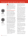
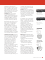
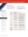
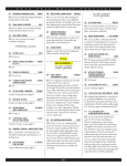
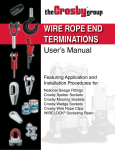
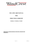
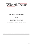
Oil & Gas
Drilling
User’s
Guide
CONTENTS
Choosing the right wire rope. . . . . . . . . . . . . . . . . . . . . . . . . . . . . . . . . . . . . . . 4
Rotary drilling rigs. . . . . . . . . . . . . . . . . . . . . . . . . . . . . . . . . . . . . . . . . . . . . . . . 6
Offshore rigs and cranes. . . . . . . . . . . . . . . . . . . . . . . . . . . . . . . . . . . . . . . . . . 7
Wire rope weights and minimum breaking force. . . . . . . . . . . . . . . . . . . . . 8
Installing and maintaining drill lines. . . . . . . . . . . . . . . . . . . . . . . . . . . . . . . . 9
Cutting drill lines. . . . . . . . . . . . . . . . . . . . . . . . . . . . . . . . . . . . . . . . . . . . . . . . . 10
Wire rope inspection program. . . . . . . . . . . . . . . . . . . . . . . . . . . . . . . . . . . . . 12
Identifying and correcting common wire rope problems.. . . . . . . . . . . . . 14
Inspecting equipment and protecting yourself. . . . . . . . . . . . . . . . . . . . . . 15
2
Union A WireCo WorldGroup Brand
2
Let us show you the ropes.
I
t takes more than the right wire
ropes to operate your rigs. It
also takes the right knowledge
and experience. When you know the
ropes – that is, how to choose, use
and maintain each of the many types
of ropes – you’ll know how to assure
maximum service life and performance
for each drilling application.
When it comes to showing you the
ropes, no one does it like Union, a
WireCo WorldGroup brand. We offer
what you need for many different
applications. And we offer the right
experience to help you when you
have questions, including how to help
maximize your wire rope’s service life
and performance.
This Oil & Gas Drilling User’s Guide
is only one example. On the following
pages, you’ll gain valuable information
to help you:
CHOOSE THE RIGHT WIRE ROPES
Knowing the ropes starts by
understanding the wide variety of
wire ropes available for the petroleum
industry. This guide contains
practical information as well as the
recommended wire ropes to use for
each application.
INSTALL WIRE ROPES Find out the
proper procedures to install a drill line
outlined in this useful guide.
INSPECT YOUR ROPES By regularly
inspecting wire ropes, you’ll not only
know when to replace them, but also
identify unusual wear patterns or abuse
that could be caused by correctable
conditions on the equipment.
EXTEND ROPE’S SERVICE LIFE
THROUGH OUR CUT-OFF PROGRAM
By moving your drill line through the
system so the wear is distributed more
evenly, you can maximize your rope’s
service life. This guide reviews this
proven practice.
IDENTIFY AND PREVENT COMMON
PROBLEMS IN THE FIELD This guide
also helps you recognize and prevent
some of the more common causes
of wire rope problems in the field,
including crushing, premature wear
on the drum and spooling problems.
TESTED, TOUGH & TRUE™
At Union, we understand the oilfield
market. Our years of climbing on the
rigs with you, combined with the
latest metallurgical practices and
unique design capabilities, have
enabled us to continue to innovate
and provide the most cost-effective
line of oilfield ropes in the world.
Union is part of the global leader
in manufacturing, engineering and
distributing wire ropes, synthetic
ropes, wire rope assemblies, high
carbon wire, and electromechanical
cable: WireCo WorldGroup. We apply
thorough design and manufacturing
controls – including complete material traceability. And we are the only
wire rope manufacturer in the world
that is QPL qualified, API certified, and
registered to both ISO 9001:2000 and
AS-9100 Quality Systems.
Buy the best:
Union – Tested, Tough & True
Union A WireCo WorldGroup Brand
3
3
Choose the right wire rope for your application.
A
ll wire ropes include a
combination of characteristics
that give them specific
performance traits depending on design,
engineering, materials and composition.
With the many specialized procedures
required for efficient well drilling, it is
important to select ropes that are best
suited for each application. No single
rope can do it all.
IF YOU NEED
ABRASION
RESISTANCE
>Abrasion resistance
increases with fewer,
larger outside wires
per strand.
IF YOU NEED
FATIGUE
RESISTANCE
>Fatigue resistance
increases with more,
smaller outside wires
per strand.
DESIGN CHARACTERISTICS OF WIRE ROPE
Consider how the composition of
a rope can affect its performance
characteristics. A rope with fewer,
but larger, outside wires per strand
will deliver more abrasion resistance
because of the greater rope surface
area exposed to drums and sheaves.
However, this most often results in a
reduction of fatigue resistance.
A greater number of smaller outside
wires per strand allows the rope to bend
more freely which will increase fatigue
life, but at the same time the smaller
wires are more susceptible to abrasion.
Additional choices in design can modify
these characteristics. You may choose a
rope with more wires in each strand for
increased fatigue resistance and with
compacted strands, which will also
provide increased abrasion resistance.
Choose the rope you need based on
the type of operation to be performed.
Different tasks demand different
characteristics and the right rope for
each task can be critical to the overall
success of operations. The primary
characteristics you will need to
evaluate include several rope design
characteristics.
>FATIGUE RESISTANCE Fatigue
resistance involves metal fatigue of
the wires that make up a rope. To have
high fatigue resistance, wires must
be capable of bending repeatedly
under stress – for example, a rope
passing over a sheave.
4
Union A WireCo WorldGroup Brand
4
Increased fatigue resistance is
achieved in a rope design by using
a large number of wires. It involves
both the basic metallurgy and the
diameters of wires.
In general, a rope made of many wires
will have greater fatigue resistance
than a same-size rope made of fewer,
larger wires because smaller wires
have greater ability to bend as the
rope passes over sheaves or around
drums. To overcome the effects of
fatigue, ropes must never bend over
sheaves or drums with a diameter
so small as to permanently bend the
wires or rope. There are precise
recommendations for sheave and
drum sizes to properly accommodate
all sizes and types of ropes.
Every rope is subject to metal fatigue
from bending stress while in operation,
and therefore the rope’s strength
gradually diminishes as it is used.
>ABRASION RESISTANCE (Resistance
to metal loss and deformation) Metal
loss refers to the actual wearing
away of metal from the outer wires
of a rope, and metal deformation is
the changing of the shape of outer
wires of a rope.
In general, resistance to metal loss
by abrasion (usually called “abrasion
resistance”) refers to a rope’s ability
to withstand metal being worn away
along its exterior. This wear reduces
the strength of a rope.
The most common form of metal
deformation is usually referred to
as “peening” since outside wires
of a peened rope appear to have
been “hammered” along their
exposed surface.
Peening usually occurs on drums,
caused by rope-to-rope contact during
spooling. It may also occur on sheaves.
Peening causes metal fatigue, which
in turn may cause wire failure. The
hammering – which causes the
metal of the wire to flow into a new
shape – realigns the grain structure
of the metal, thereby affecting its
fatigue resistance. The out-of-round
shape also impairs wire movement
when the rope bends.
>STRENGTH Wire rope strength
is usually measured in tons of
2,000 lbs. In published material, wire
rope strength is shown as minimum
breaking force (MBF) – referring to
calculated strength figures that are
accepted by the wire rope industry.
When placed under tension on a test
device, a new rope will break at a
figure equal to – or higher than –
the MBF shown for that rope.
Minimum breaking force applies to
new, unused rope. A rope should
never operate at – or near – its MBF.
During its useful life, a rope loses
strength gradually due to natural
causes such as surface wear and
metal fatigue. Sudden loss of strength
can be caused by abusive situations.
>CRUSHING RESISTANCE Crushing
is the result of external pressure on a
rope, which damages it by distorting
the cross-section shape of the rope,
its strands or core – or all three.
Crushing resistance therefore is
a rope’s ability to withstand or
resist external forces, and is a
term generally used to express
comparison between ropes.
When a rope is damaged by crushing,
the wires, strands and core are
prevented from moving and adjusting
normally during operation.
In general, IWRC ropes are more
crush resistant than fiber core ropes.
Regular lay ropes are more crush
resistant than lang lay ropes. Sixstrand ropes have greater crush
resistance than eight-strand ropes or
19-strand ropes. Flex-X ® ropes are
more crush resistant than standard
round-strand ropes.
>STABILITY The word “stability” is
most often used to describe handling
and working characteristics of a rope.
It is not a precise term since the idea
expressed is to some degree a matter
of opinion, and is more nearly a
“personality” trait than any other
rope feature.
For example, a rope is called stable
when it spools smoothly on and off
a drum – or doesn’t cause the ropes
to twist together when a multi-part
reeving system is used.
“SQUARED ENDS”
>Typical example of
breaks due to fatigue.
“CRUSHING”
>Typical example of
external pressure on
a wire rope.
Strand and rope construction
contribute to stability for the most
part. Regular lay rope tends to be
more stable than lang lay. A rope
made of seven-wire strands will
usually be more stable than a more
complicated construction with many
wires per strand.
CROSS- SECTION
OF A WORN WIRE
>Original
cross-section
There is no specific measurement
of rope stability.
>Worn
surface
>BENDABILITY Bendability relates
to the ability of a rope to bend easily
in an arc. Four primary factors affect
this capability:
1.Diameters of wires that make up
the rope.
2.Rope and strand construction.
CROSS- SECTION
OF A PEENED WIRE
3.Metal composition of wires
and finish such as galvanizing.
>Original
cross-section
4.Type of rope core – fiber core
or IWRC.
>Peened
surface
Some rope constructions are by
nature more bendable than others.
Small ropes are more bendable than
big ones. Fiber core ropes bend more
easily than comparable IWRC ropes.
As a general rule, ropes of many wires
are more bendable than same-size
ropes made with fewer, larger wires.
Union A WireCo WorldGroup Brand
5
5
The right ropes for oil and gas drilling operations.
TYPICAL WIRE ROPES FOR
ROTARY DRILLING OPERATIONS
The various lines for rotary drilling rigs
require a complex balance of wire rope
characteristics: abrasion resistance,
crush resistance, fatigue resistance,
strength, bendability and stability.
GUIDELINES ON VISIBLE
CLEARANCE BETWEEN
STRANDS*
WIRE ROPES FOR DRILLING APPLICATIONS
>Clearances are designed
between adjacent strands
to allow movement when
the rope is bent. In a new
rope, because the strands
have not pulled down to
their tightest position, the
clearances between strands
are greater. A further
APPLICATION
Rotary drilling line
accentuation of this occurs
as frequently the clearances
accumulate between two
strands instead of being
equally divided among all
strands. This will even out
once the rope is placed
in service. A final factor
that makes the rope on a
reel appear to have more
clearance between the
strands is because only the
outside bend is visible and
clearance is greatest on
the outside radius of a bent
rope.
Sand line
Mast raising
line
Air hoist
Geronimo
Tong line
This condition is normal and
the rope should be used,
maintained, inspected
and retired per applicable
standards.
*Wire Rope Technical Board,
Derrick assist
Block tie back
Technical Bulletin, Dec. 2006
6
Union A WireCo WorldGroup Brand
Each rig is different, of course, but
the chart below provides general
guidelines for selecting the right rope.
For more specific recommendations,
consult WireCo WorldGroup Technical
Support: 816.270.4700.
6
RECOMMENDED WIRE ROPE
Tuffy Balanced Drill Line
7/8” to 1-1/8”
6 x 26WS RRL IWRC
1-1/8” to 1-1/2”
6 x 19S RRL IWRC
1 - 5/8” to 2-1/4”
6 x 26WS RRL IWRC
Above sizes and
constructions available
in TUF -KOTE ®
and TUF-FLEX®
COMMENTS
This demanding application
requires a rope that is abrasion
resistant, crush resistant, fatigue
resistant and relatively stable.
Premium ropes may be used for
specific applications.
Tuf -Kote cushions the strands,
distributes internal stresses,
keeps in wire rope lubricant
and keeps out dirt and debris,
extending the service life.
Flex-X ropes provide additional
strength, more wear resistance,
more fatigue resistance and
more crush resistance.
1/4” through 5/8”
These ropes have larger outside
6 x 7 RRL IPS FC
wires to resist wear and help
reduce costs.
1 - 3/8” and smaller
Construction selected for
6 x 19 class IWRC
balance of wear resistance and
durability. Right regular lay or
1 - 1/2” and larger
right lang lay is commonly used.
6 x 36 class IWRC
Never mix right and left lay mast
raising lines.
6 x 26WS RRL IWRC
Better crushing and abrasion
resistance than a 6 x 25 rope.
6 x 36WS RRL IWRC
Increased bendability and fatigue
resistance.
TYPICAL WIRE ROPES FOR
OFFSHORE OPERATIONS
Offshore rigs and cranes need
wire ropes that rely on a different
set of performance characteristics.
Maintaining a stable platform in
deep water, subject to constant
battering by wind and waves,
requires a system of powerful
anchoring lines and tensioner
cables with excellent bendability,
fatigue and abrasion resistance.
On deck, wire ropes are needed
to operate cranes, moving heavy
loads to and from the rig with
a minimum of maintenance and
downtime. A variety of wire ropes
are available for offshore cranes.
The chart at the right describes
some of the typical ropes, their
usages and traits.
WIRE ROPES FOR OFFSHORE APPLICATIONS
RECOMMENDED APPLICATIONWIRE ROPE
COMMENTS
Anchor line
6 x 19 class RRL bright
or galvanized IWRC
6 x 36 class RRL bright
or galvanized IWRC
Choice depends upon rope size
required, drum geometry and
other operating characteristics.
The 6 x 19 ropes have larger
outside wires for more abrasion
resistance.
The 6 x 36 ropes have a greater
number of outside wires for extra
bendability and fatigue resistance.
Buoy pendant
6 x 36 class RRL bright
or galvanized IWRC
Riser tensioner 6 x 36 class RLL IWRC
line (MRT)
8 x 36 class RLL IWRC
Flex-X® 6 MRT or
Flex-X® 8 MRT
Guide line
6 x 26WS RRL IWRC
tensioner line
Offers good fatigue resistance.
A lang lay construction is
recommended because both
ends of the rope are fixed and
it is more resistant to fatigue
than regular lay.
Flex-X ropes increase strength
and resistance to wear, fatigue
and crushing.
The 6 x 26 ropes provide a
good balance between abrasion resistance and fatigue resistance.
WIRE ROPES FOR OFFSHORE CRANE APPLICATIONS
RECOMMENDED APPLICATIONWIRE ROPECOMMENTS Hoist
Category 1 rope
Flex-X ® 19 19 x 7
6 x 26WS
Provides the best rotation
resistance, more lifting capacity
and fatigue resistance.
Flex-X 19 provides a great
combination of rotation resistant
properties and improved stability
and resistance to crushing.
Lower strength and less wear
resistance than Flex-X 19, but
does provide rotation resistance.
May be used if block rotation
is not a problem.
Boom hoistFlex-X® 9
Flex-X® 6
6 x 26WS RRL IWRC
Flex-X 9 is designed to provide
the resistance to drum crushing
that is critical in many boom
hoist applications.
Flex-X 6 provides resistance
to bending fatigue, as well as
stability.
Crane manufacturers specify
a number of boom hoist ropes,
but these are the most common.
Check your owner’s manual
to assure ropes meet strength
requirements.
Boom pendant
Rope or strand Custom-fabricated to
your requirements.
Another member of the WireCo
WorldGroup family is CASAR.
Our proprietary and innovative
German-engineered rope
designs deliver the highest
levels of performance and
safety, superior breaking
strength values, the highest
bending fatigue resistance,
superior crushing resistance,
and the best rotational
resistance characteristics for
high lifts.
For more information reference
www.casar.de
Union A WireCo WorldGroup Brand
7
7
Wire rope weights and minimum breaking force.
FLEX-X AND
INCREASED
SURFACE AREA
>Flex-X ropes provide
greater surface
area and more steel
per given diameter,
increasing rope
stability, strength –
and service life.
T
he 6 x 19 classification of wire
ropes includes standard six
round strand ropes with 16
through 26 wires per strand. The
6 x 36 classification includes standard
six round strand ropes with 27 to 49
wires per strand.
have more fatigue resistance because
they have more wires per strand.
The Flex-X ® process provides a
smooth, extremely compact wire
rope with greater surface area
and more steel per given diameter,
which increases strength, fatigue
resistance and wear resistance.
Although the physical characteristics
of these two can vary widely, both
have the same weight per foot and
the same minimum breaking force, size
for size. While 6 x 19 ropes have more
abrasion resistance, the 6 x 36 ropes
When Union’s Flex-X products are
properly matched to the application,
you’ll get longer service life, lower
operating costs and less wear to
sheaves and drums.
WIRE ROPE MINIMUM BREAKING FORCE AND WEIGHTS
6 X 19, 6 X 36 IWRC
TUF-FLEX ® DL
Diameter
(in)
8
FLEX-X ® 19
MinimumMinimum
Breaking
BreakingMinimumMinimumMinimum
ForceForceBreakingBreakingBreaking
XIP®
XXIP®Approx.
ForceApprox.
ForceApprox.
Force
Approx.
(tons of
(tons of
Weight
(tons of
Weight
(tons of
Weight
(tons of
Weight
2000 lb) 2000 lb)
(lb/ft)
2000 lb)
(lb/ft) 2000 lb)
(lb/ft)
2000 lb)
(lb/ft)
1/4 5/16 3/8 7/16 1/2 9/16 5/8 3/4 7/8 1 1-1/8
1-1/4
1-3/8
1-1/2
1-5/8
1- 3/4
1-7/8
51.7
65
79.9
96
114
132
153
174
2 2-1/8
2-1/4
2- 3/8
2-1/2
2-5/8
2-3/4
2-7/8
3 Union A WireCo WorldGroup Brand
FLEX-X ® 9
3.4
5.27
7.55
10.2
13.3
16.8
20.6
29.4
39.8
198
221
247
274
302
331
361
392
425 8
— — 8.3
11.2
14.6
18.5
22.7
32.4
43.8
56.9
71.5
87.9
106
125
146
169
192
217
244
272
—
—
—
—
—
— 0.116
0.18
0.26
0.35
0.46
0.59
0.72
1.04
1.42
1.85
2.34
2.89
3.5
4.16
4.88
5.67
6.5
7.39
8.35
9.36
10.4
11.6
12.8
14
15.3
16.6
— — —
—
—
—
—
—
—
71.5
87.9
106
125
146
169
192
217
244
272
—
—
—
—
—
— — — —
—
—
—
—
—
—
— — — — — — — — — — — — 26.2 0.9
37.4 1.3
50.6 1.8
— — — — 8.3
0.3
11.2
0.4
14.6
0.5
18.5
0.7
22.70.8
32.41.2
43.81.6
65.7 2.3 56.92.1
2.5
82.7
2.9
71.5
2.6
3.1
102 3.7 87.9
3.1
3.7
— — 106
—
4.5
— — 125
—
5.2
— — — —
6.1
— — — — 7.0
— — — — 7.9
8.9 10.0 — — — — — — —
—
—
—
—
—
—
—
— —
—
—
—
—
—
—
—
— —
—
—
—
—
—
—
—
—
—
—
—
—
—
—
—
— —
Guidelines for installing and operating drill lines.
INSTALLATION
1.Use a rope connector grip (snake)
with a swivel to connect the new
drill line to the old drill line. This will
relieve twist that may be put in the
rope during spooling and handling.
2.Never weld the new drill line to the
old drill line.
3.Try to install the new drill line at a
point in the drilling operation when
there is a considerable amount of
weight available to help seat (break in)
the new drill line and assist spooling.
4.Remove and inspect the brass inserts
on the dead line anchor for proper
size and if worn, replace. Rope must
be seated properly in the clamp to
avoid damage when torqued down.
Torque the nuts on the dead line
anchor clamp to the manufacturer’s
specifications. Torque should be
rechecked after one to two hours
of operation. (Refer to page 12 for
inspection information.)
5.Special care should be taken during
rig moves to prevent damage of the
drill line such as kinks and doglegs.
OPERATION/SETTING CASING
1.The optimum service is received
when the drill line operates with a
design factor ranging from 5 to 7. A
high design factor (over 7) wears the
drill line out from bending fatigue
because ton-miles do not accumulate
as fast as at lower design factors.
2.The upper layer of the drill line can
pull down through lower layers on
the drum when setting heavy loads.
This occurs because the block goes
up empty with very little load. The
drill line is not spooled tightly on the
drum. The load is then applied to
the drill line on the top layer which
forces the wraps on the next lower
layer apart allowing the top wrap
to pull down. Using a heavier block
or by adding “cheek” plates to the
block will lessen the problem.
3.Rope service increases with fewer
parts of lines. The fewer the number,
the less rope is spooled on the drum
so less rope is subjected to the
crossover points on the drum. It
also allows more rope available to
cut. As an example, on a 7500’ reel,
if 12 lines are strung there is approximately 2200’ of rope in the string-up
or 5300’ of rope available to cut. For
10 lines, there is 1900’ of rope in the
string-up, or 5600’ of rope available
to cut. This would increase rope
service by over 5%.
4.Always make a cut based on tonmiles accumulated prior to and after
setting a heavy load of casing.
5.If the design factor for setting the
casing is approximately 3.0, cut a
minimum of 200’ from the string-up.
Inspect the remaining rope and make
another cut if necessary.
BRASS INSERTS ON
DEAD LINE ANCHOR
>Remove and inspect
the brass inserts on
the dead line anchor
for proper size and, if
worn, replace.
Rope must be seated
properly in the clamp
to avoid damage when
torqued down.
6.If the design factor is down to 2.0
(the lowest allowed by API), cut a
minimum of 600’ from the string-up.
After inspection, make another cut
if necessary.
7.For design factors between 2.0 and
3.0, cut between 200’ and 600’. Make
another cut if needed after inspection.
8.Try not to install a new drill line
(or slip all new rope into the system)
just before setting a heavy load of
casing. New or unused rope is more
susceptible to crushing than a rope
that has been in service.
Union A WireCo WorldGroup Brand
9
9
Union provides excellent expertise in the field.
EXCLUSIVE CUT-OFF PROGRAM
hile there are other cut-off programs
available, contractors around the world
consider the Union cut-off program as
the best in the industry. Our computerized cut-off
program calculates, logs, and tracks the
service life of your Union drilling
line. More importantly, it provides
the tools to assure that you receive
the maximum service life for your
drill line. While the Union Cut-Off
Program was originally developed
more than 30 years ago to help
our drill line users obtain the
maximum service, we continually
look for ways to expand and improve its
functionality exclusively for our customers.
W
Our latest version of the cut-off program is available
through a USB flash drive that can be plugged in
directly to the USB port of any computer and is
compatible with both Windows and Apple operating
systems. This program is available in English,
Spanish, Russian, and Portuguese, and you can
choose your unit of measure as ton-miles, tonnekilometers or megajoules. The program calculates
the load and the distance lifted or lowered. You
can set up a Ton-Mile goal and when that goal is
reached, additional rope can be unspooled from
the storage reel and slipped though the system.
The used rope is then cut off and discarded. For
an accurate record of the amount of work done
by a drilling line, it is necessary to calculate the
weight being lifted and the distance it is raised and
lowered.
In order for the program to properly recommend
when to make a cut and determine how much
rope needs to be cut, the user must input a correct
“Goal”. This “Goal” should be entered as “tonmiles per foot cut”, “tonne-kilometers per meter
cut”, or “megajoules per meter cut” depending on
the units selected. Additionally, the program has
certain goal limitations that it will not allow you to
exceed and also will not recognize goals in the form
of “ton-miles per 100 foot cut”. For example, a slip
10
Union A WireCo WorldGroup Brand
10
and cut program of cutting 100 feet of rope after
1800 ton-miles have been accumulated will need
to be entered as a Goal of 18 ton-miles per foot cut,
not 1800. The Union Wire Rope team can help you
determine the recommended goal for your specific
rig based on information about your rig.
Union has the most qualified and dedicated team
of engineers and sales professionals in the world.
Their years of field experience, unmatched depth of
knowledge and expertise sets the standard for our
industry.
TECHNICAL TRAINING AND SEMINARS
Our experts conduct technical training for rig
managers and tool pushers throughout the globe on
a wide variety of topics such as installation, usage,
rope inspection and retirement, and how to use our
cut-off program. We can tailor our seminars to help
you maximize the service life of your wire ropes. We
are there for you.
Our expertise and experience can also provide
invaluable assistance in the field. Our staff is
available for rope inspections, on site consultation
and problem solving.
No matter where you are in the world, Union
delivers hard-working products, exceptional service
and unmatched support. At Union, we’re with you
in the field and on the rig, getting our hands dirty
to supply Tested, Tough & True wire ropes that
help you get the job done. Being part of the global
wire rope leader, WireCo WorldGroup, ensures you
can count on Union wire ropes for the toughest
applications in your industry.
Guidelines for making drill line cuts.
S
ervice life of drilling lines can be increased
dramatically by following a planned cut- off
program based on work performed. This
moves the rope through the system so wear can
be spread uniformly along the entire length of the
rope, enabling the line to be removed from the drum
end when it has reached the end of its useful service
life. As the rope is cut off the drum end, new rope is
fed into the system on the dead line side, extending
service life. When exercising a cut-off program, follow
the guidelines below closely.
A 10-STEP GUIDE TO A DRILL LINE CUT-OFF PROGRAM
1. For the first few cuts, wrap the drill line at the point being cut with duct tape prior to making the cut to prevent
unlaying.
2. When making a cut and slipping new rope into the
string-up, all of the wraps should be removed from
the deadline anchor. The rope should never be pulled
through a loosened clamp which can put a twist in the
rope. The clamp should be completely removed and
inspected. If worn or damaged, replace.
3. After making a cut, the dead wraps should be spooled
on the drum with sufficient tension to prevent excessive
drum crushing or “milking” of the bottom layer.
4. Take ton - miles for drag into account.
5. Drill ships and semis using a crown motion compensator
may operate with a lower ton - mile goal due to additional
sheaves and extra rope on the drum.
6. Extended drilling between round trips may necessitate
making a cut to avoid exceeding maximum allowable
ton - miles.
7. Because of the additional weight, top drives accumulate
more ton - miles for each rig operation. It has not been
determined if ton - mile goals should be changed to
accommodate this.
8. Short, frequent cuts will shift critical wear points
caused by excessive jarring.
9. Long cuts are necessary when the amount of rope
to be cut doesn’t remove all the rope that meets
removal criteria. This can be caused by failure to
follow the ton - mile goal, improper calculation or
recording of ton - miles. Damage at any point may
require a long cut.
10. To prevent long cuts:
a. Find the optimal ton - mile goal for your drill line;
experience may indicate you have to change your
ton - mile goal. It’s important to follow the cut- off
program for a new rope. The first few cuts may
seem excessive, but they are necessary to move
rope through the system at the proper rate.
b. Ton - miles must be calculated and recorded
accurately for each operation.
c. Inspect equipment to prevent conditions that
adversely affect service life. Equipment problems
such as bearing failure in a sheave can cause
unusual wear leading to long cuts.
Union A WireCo WorldGroup Brand
11
11
Make the most of your wire rope through
regular inspections.
D
espite their durability and strength, wire
ropes will eventually wear out and must
be removed after a period of use. That’s
why regular inspection is crucial.
wires in six rope diameters – or four randomly
distributed broken wires in 30 rope diameters.
Sand lines should be removed from service when
you see three broken wires within one lay length.
HOW OFTEN TO INSPECT
All hoisting lines should be visually inspected at
least once each day when in use, as is suggested
by American Petroleum Institute (API) RP54 guidelines. Hoisting lines should be thoroughly inspected
once each month and a record made of the monthly
inspection.
WHEN TO REPLACE STANDING ROPES
DUE TO BROKEN WIRES
Wire ropes used as standing ropes such as guy
lines, escape lines and pendant lines should be
removed from service when any of the following
conditions exist:
Any wire ropes that have met the following criteria
for removal must be immediately replaced. When
in doubt, replace. The cost is minimal compared
to what could happen if your rope breaks.
>More than one broken wire is found at the
end connection.
WHEN TO REPLACE RUNNING ROPES
DUE TO BROKEN WIRES
Wire ropes used as running ropes other than sand
lines should be removed from service when broken
wires meet any of the following criteria:
>For six- and eight-strand constructions, replace
when you see six randomly distributed broken
wires within one lay length, or three broken
wires in one strand within one lay length.
>For rotation-resistant constructions, replace
when you see two randomly distributed broken
>Three broken wires are found within one
lay length.
>Broken wires are found in the valleys between
the rope’s strands.
WHEN TO REPLACE MAST RAISING LINES
DUE TO BROKEN WIRES
>One broken wire is found anywhere along the
length of the mast raising line.
OTHER REASONS TO REPLACE ROPES
Broken wires are only one way wire ropes wear
out. Other conditions for removal of wire rope from
service are:
>Corrosion that pits the wires.
>Corroded wires at end connections.
FOLLOW THESE STEPS TO INSPECT FOR VALLEY BREAKS
1.The first step is to relax your rope to a stationary
position and move the pick-up points off the sheaves.
Clean the surface of the rope with a cloth – a wire brush,
if necessary – so you can see any breaks.
2.Flex the rope to expose any broken wires hidden in the
valleys between the strands.
3.Visually check for any broken wires. One way to check for
crown breaks is to run a cloth along the rope to check
for possible snags.
4.With an awl, probe between wires and strands and
lift any wires that appear loose. Evidence of internal
broken wires may require a more extensive rope
examination.
12
Typical valley (above) and crown (below) wire
breaks in outer wires.
>API RP 9B: Recommended Practice on Application,
Care and Use of Wire Rope for Oilfield Service
For additional information and requirements, please refer to
the latest edition of:
>API RP 54: Recommended Practices for Occupational
Safety for Oil and Gas Well Drilling and Servicing
Operations
>API RP 2D: Recommended Practice for Operation
and Maintenance of Offshore Cranes
>ASME B30.5: Mobile and Locomotive Cranes
(crane rope removal criteria)
Union A WireCo WorldGroup Brand
12
>End connections that are corroded, cracked,
bent, worn or improperly applied.
>Evidence of kinking, crushing, cutting,
bird-caging or a popped core.
>Wear that exceeds one-third of a wire’s
original diameter.
>Severe reduction of the rope’s diameter.
>Evidence of heat damage.
>A significant increase in lay length.
HOW TO FIND BROKEN WIRES
One of the most common signs of rope deterioration
is broken wires, normally the outside wires on the
crowns of the strands.
RUNNING ROPES Because of their contact with
sheaves and drums, running ropes typically receive
heavier external wear than standing ropes. This
can result in surface wire breaks – the easiest kind
to locate during your inspection. The challenge is
to find valley wire breaks. These may occur when
ropes are used with small diameter sheaves, sheave
grooves that are too small, heavy loads and other
poor operating conditions. During your inspection,
pay close attention to the areas of the rope in
contact with sheaves and drums when loads are
picked up. If there is a reason to suspect valley
wire breaks, such as a reduction in rope diameter
or elongation of rope lay, perform an inspection as
outlined below for standing ropes.
STANDING ROPES Most wire breaks in standing
ropes are internal (or valley) breaks that occur at
the points of wire contact. Inspection will reveal
no surface wear and therefore nothing to cause
external wire breaks. The majority of broken wire
problems on standing ropes occur near the end
attachments or other points of restriction where
vibration is dampened.
ROPE INSPECTION CRITERIA FOR DRILLING OPERATIONS
All portions of wire rope must be inspected thoroughly for
possible deterioration on a regular basis. This starts with
a close examination of the rope’s critical points. The critical
points of an application are those that subject the rope to
greater internal stresses or greater external forces. Rope
wear is more likely in the following critical areas, so it pays
to closely inspect these areas:
DRUMS When the rope spools properly, normal wear
occurs at the crossover, kickover and change -of-layer
points. Look for scrubbing on the side of the rope; in other
words, rope that rubs against the preceding wrap on the
drum. Crushing may result on rope’s top and bottom sides.
If severe, remove the rope from service. Both the scrubbing
and the crushing normally occur twice with each drum
revolution.
Inspection of drums is also critical. Check for signs
of wear that could damage wire rope. All drums should
be smooth, not corrugated. Check for minimum number
of dead wraps remaining on the drum, the spooling
characteristics of rope and the condition of flanges.
SHEAVES It’s very important to check for broken wires in
the wire ropes traveling over the sheaves in your system.
(See section on broken wires on facing page.)
Grooves tend to wear smaller over time, especially under
heavy loading conditions. With a groove gauge, check each
sheave for proper sizes, as well as their smoothness.
Grooves that are too small or tight can cause pinching
and increased abrasion while grooves that are too wide can
cause flattening of the rope – both of which can reduce
your rope’s life. Also inspect for corrugation, broken or
chipped flanges, cracks in hubs and spokes, signs of rope
contact with guards, sheave bearings and shaft, an outof-round condition, and alignment with other sheaves – all
criteria for replacement.
END ATTACHMENTS Rope adjacent to end attachments has
its movement restricted and is subject to fatigue as rope
vibrations are dampened. Inspect with an awl to expose
broken wires, and if more than one broken wire is found,
replace the rope. Be sure to also inspect the fitting itself.
OTHER IMPORTANT AREAS TO INSPECT:
PICK-UP POINTS The sections of a rope that contact
sheaves or drums when the initial load is applied.
HEAT EXPOSURE If an electric arc contacts the rope,
remove the entire rope from service immediately. Although
the problem may not be visible, electric arcs can affect the
rope’s properties and the rope needs to be replaced.
ABUSE POINTS Look for “bright” spots where ropes
are subjected to abnormal scuffing and scraping.
Union A WireCo WorldGroup Brand
13
13
How to identify and correct common rope
problems in the field.
REDUCING CRUSHING AND SCRUBBING
DAMAGE ON WIRE ROPE
CRUSHING When a wire rope crosses over the
preceding layer on the drum, it is susceptible to
crushing because there is only a single point of
contact. This increases pressure and can result in
damage by distorting the cross-section shape of
the rope, its strands or core – or all three. Ropes
that are new or not spooled onto the drum under
tension are also more susceptible to crushing.
In addition, crushing may occur at the changeof-layer point where the rope is wedged against
the flange of the drum.
SCRUBBING As the rope spools on the drum, it
rubs against the preceding wrap at the kickover
points, making the sides of the rope vulnerable to
scrubbing damage. Scrubbing occurs most commonly
when the rope runs into its preceding wrap in the
same valley between two ropes on the lower layer.
It can also occur as the adjacent rope comes into
contact as a result of fleet angle.
FACTORS AFFECTING ROPE WEAR
The degree of scrubbing and crushing damage
depends on a variety of factors, such as rope
construction, previous usage of the rope, the
load on the rope, the drum diameter, the number
of layers and the pitch of the grooving.
Single-layer winding on a plain-faced drum is more
likely to produce an increased rate of wear to both
the rope and drum compared to a grooved drum.
Grooved drums control the position of the base
rope layer, thereby reducing some types of
spooling problems.
FIELD SOLUTIONS
If crushing is a problem on drill lines, one solution
is to go to more parts of line to reduce the load in
the wire rope. This will result in longer string-up
and may cause less service from your drill line. If
crushing proves to be a continual problem, drum
modifications may help.
14
Union A WireCo WorldGroup Brand
14
COUNTERBALANCE GROOVING
Counterbalance grooving
has smaller displacement
on the drum, which is less
damaging at each crossover
point compared to helical
or parallel grooving. This
reduces scrubbing problems
at the kickover points as
well as line “whipping.”
It also keeps the drum in
balance by placing the kickover points halfway around
the drum from each other.
IMPROPER TENSIONING
Insufficient tensioning of the first two or three layers
of rope can also cause
rope wear by allowing
“pulling in” by subsequent layers of rope.
Without enough
tension, these lower
layers can be pushed
apart by the upper
layers. The upper
layers then become
wedged into the lower layers, which can distort the
rope and/or individual wires.
WHIPPING
Rope whipping or vibration is another problem that
may be encountered with high line speeds and
multiple layer winding. Whipping is introduced by
the lateral displacement or “throw” of the rope at
the crossover points. When a wave is thrown into a
rope by a crossover, this disturbance travels along
the rope and is reflected back at the sheave at a
speed relative to its weight and tension.
To reduce whipping problems, a line guide can be
used between the drum and the crown sheaves.
Inspect your equipment.
IN ADDITION TO CAREFUL ROPE
INSPECTION, PERFORM THESE
EQUIPMENT INSPECTIONS ON A
REGULAR BASIS.
1.Check the traveling block and crown
sheaves. If the depth or size of the
groove shows excessive wear, the
sheaves must be replaced or repaired
(especially the fast line sheave).
2.Check the lagging on the drum for size
and smoothness. If excessively worn
or corrugated, repair or replace it.
3.The kick back plates, kick back rollers
and line guide roller assembly should
be inspected periodically.
4.Rope should be removed from service
if it meets the retirement criteria
specified by API RP54.
INSPECT YOUR
EQUIPMENT AND
WIRE ROPE
REGULARLY
>Inspection should
be performed by a
person with special
training or practical
experience.
Protect yourself
I
n the real world, accidents do happen,
and that’s why you need to take
special precautions. Before installing
wire rope in your applications, always
read and follow the warning label
attached to each product.
?
NEED MORE
INFORMATION?
>When it comes to
oil and gas drilling,
knowledge is your
most important tool.
We know this guide
can’t answer every
question you have
about wire rope.
If you have more
informational needs,
contact your Union
distributor or district
sales manager.
WARRANTY
Any warranty, expressed or implied as to quality, performance or fitness for use of WireCo WorldGroup products
is always premised on the condition that the published strengths apply only to new, unused products, that the
mechanical equipment on which such products are used is properly designed and maintained, that such products are
properly stored, handled, used and maintained, and properly inspected on a regular basis during the period of use.
Seller shall not be liable under any circumstances for consequential or incidental damages or secondary charges
including but not limited to personal injury, labor costs, a loss of profits resulting from the use of said products or from
said products being incorporated in or becoming a component of any other product.
Union A WireCo WorldGroup Brand
15
15
+1.816.270.4700
info @wirecoworldgroup.com
12200 NW Ambassador Drive
Kansas City, MO 64163 -1244 USA
fax: +1.816.270.4707
www.UnionRope.com
©2014 WireCo WorldGroup
Form No. 1012H
SPEC 9A-0022