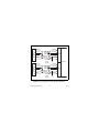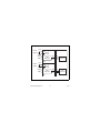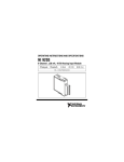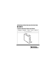
1
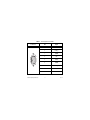
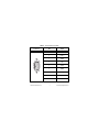
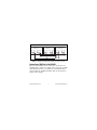
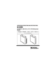
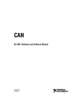
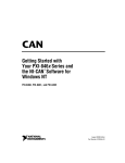
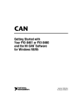
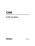
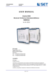
OPERATING INSTRUCTIONS NI 9852 2-Port, Low-Speed/Fault-Tolerant CAN Module These operating instructions describe how to use the National Instruments (NI) 9852 module. For information about installing, configuring, and programming your system, refer to your system documentation. The NI 9852 module requires the NI 985x software (version 1.2 or higher) to be installed. The latest version of the NI 985x software is located at ni.com/downloads. The safety guidelines and specifications in this document are specific to the NI 9852. The other components in your system may not meet the same safety ratings and specifications. Refer to the documentation for each component in your system to determine the safety ratings and specifications for the entire system. Note Safety Guidelines Operate the NI 9852 only as described in these operating instructions. This icon denotes that the component may be hot. Touching this component may result in bodily injury. Hot Surface NI 9852 Operating Instructions 2 ni.com Safety Guidelines for Hazardous Locations The NI 9852 is suitable for use in Class I, Division 2, Groups A, B, C, D, and T4 hazardous locations; Class 1, Zone 2, AEx nA II T4 and Ex nA II T4 hazardous locations; and nonhazardous locations only. Follow these guidelines if you are installing the NI 9852 in a potentially explosive environment. Not following these guidelines may result in serious injury or death. Caution Do not disconnect I/O-side wires or connectors unless power has been switched off or the area is known to be nonhazardous. Caution Do not remove modules unless power has been switched off or the area is known to be nonhazardous. Substitution of components may impair suitability for Class I, Division 2. Caution For Zone 2 applications, install the CompactRIO system in an enclosure rated to at least IP 54 as defined by IEC 60529 and EN 60529. Caution © National Instruments Corp. 3 NI 9852 Operating Instructions For Zone 2 applications, install a protection device between the CAN signals and the NI 9852 CAN pins. The device must prevent the CAN Port-to-COM voltage from exceeding 55 V if there is a transient overvoltage condition. Caution Special Conditions for Hazardous Locations Use in Europe This equipment has been evaluated as EEx nA II T4 equipment under DEMKO Certificate No. 03 ATEX 0324020X. Each module is marked II 3G and is suitable for use in Zone 2 hazardous locations. Wiring the NI 9852 The NI 9852 has two 9-pin male D-Sub connectors that provide connections to a CAN bus. Each port on the NI 9852 has pins for CAN_H and CAN_L, to which you connect the CAN bus signals. These signals should be connected using twisted-pair cable. NI 9852 Operating Instructions 4 ni.com Each port has two isolated common pins (COM) that are internally connected to the isolated reference of the module and serve as the reference ground for CAN_H and CAN_L. Connect the CAN bus reference ground (sometimes referred to as CAN_V–) to the COM pin. Each port also has an optional shield pin, SHLD, that can be connected to a shielded CAN cable. Connecting SHLD may improve signal integrity and EMC performance in a noisy environment. Both of the ports on the NI 9852 require an external power supply of +8 V to +36 V to operate. Supply power from the CAN bus to the VSUP0 pin on CAN0, and the VSUP1 pin on CAN1. Pinouts for CAN0 and CAN1 of the NI 9852 are listed in Table 1 and Table 2. © National Instruments Corp. 5 NI 9852 Operating Instructions Table 1. Pin Assignments for CAN0 Connector 6 7 8 9 1 2 3 4 5 NI 9852 Operating Instructions Pin Signal 1 No Connection (NC) 2 CAN_L 3 COM0 4 NC 5 SHLD 6 COM0 7 CAN_H 8 NC 9 VSUP0 6 ni.com Table 2. Pin Assignments for CAN1 Connector 6 7 8 9 1 2 3 4 5 © National Instruments Corp. Pin Signal 1 No Connection (NC) 2 CAN_L 3 COM1 4 NC 5 SHLD 6 COM1 7 CAN_H 8 NC 9 VSUP1 7 NI 9852 Operating Instructions CAN Bus Topology and Termination A CAN bus consists of two or more CAN nodes cabled together. The CAN_H and CAN_L pins of each node are connected to the main CAN bus cable through a short connection known as a “stub.” The pair of signal wires, CAN_H and CAN_L constitutes a transmission line. Every device on a low-speed/fault-tolerant CAN network requires a termination resistor for each CAN data line: RRTH for CAN_H and RRTL for CAN_L. Figure 1 shows a simplified diagram of a low-speed/fault-tolerant CAN bus with termination resistor placements. NI 9852 Operating Instructions 8 ni.com Low-speed/Fault-Tolerant CAN Device RTL CAN_L RTH CAN_H Low-speed/Fault-Tolerant CAN Device RTL CAN_L Low-speed/Fault-Tolerant CAN Device RTH CAN_H RTL CAN_L RTH CAN_H CAN_H CAN_L Figure 1. CAN Bus Topology and Termination Resistor Locations Connecting a CAN Bus to the NI 9852 Each port of the NI 9852 can be connected to any location on a CAN bus. Figure 2 shows one example of the connection of CAN0 of the NI 9852 directly to one CAN node, and CAN1 directly to another CAN node. CAN0 and CAN1 require an external power supply on the CAN bus. © National Instruments Corp. 9 NI 9852 Operating Instructions CAN Device (SHLD) (SHLD) CAN_H CAN_H CAN_L Vsup0 COM0 CAN Device (SHLD) CAN_H CAN_L Vsup1 COM1 CAN Cable (With Optional Shield) CAN_L CAN0 Vsup0 + – External Power Supply COM0 NI 9852 (SHLD) CAN_H CAN Cable (With Optional Shield) CAN_L Vsup1 + – CAN1 COM1 External Power Supply Figure 2. Connecting Both Ports of the NI 9852 to CAN Buses NI 9852 Operating Instructions 10 ni.com Cabling Requirements for NI 9852 This section deals with cabling specifications, termination resistors, cable lengths, and the number of CAN nodes that can exist in a system. Cable Specifications Cables should meet the physical medium requirements specified in ISO 11898, shown in Table 3. Belden cable (3084A) meets all of those requirements, and should be suitable for most applications. Table 3. Specifications for Characteristics of a CAN_H and CAN_L Pair of Wires Characteristic Value Length-related resistance 90 mΩ/m nominal Length-related capacitance: CAN_L and ground, CAN_H and ground, CAN_L and CAN_H 30 pF/m nominal © National Instruments Corp. 11 NI 9852 Operating Instructions Determining the Necessary Termination Resistance for the Board Unlike High-Speed CAN, Low-Speed/Fault-Tolerant CAN requires termination at the Low-Speed/Fault-Tolerant CAN transceiver instead of on the cable itself. Termination requires two resistors, RTH for CAN_H and RTL for CAN_L. This configuration allows the Philips Fault-Tolerant CAN transceiver to detect and recover from bus faults. It is important to determine the overall termination of the existing network, or the termination of the individual device, before connecting it to a Low-Speed/Fault-Tolerant port. Philips recommends an overall RTH and RTL termination of 100 to 500 Ω (each) for a properly terminated low-speed network. Termination on the low-speed/fault-tolerant ports of the NI 9852 is set through the NI 985x software to either 1 kΩ or 5 kΩ. NI 9852 Operating Instructions 12 ni.com Number of CAN Nodes The maximum number of nodes depends on the electrical characteristics of the nodes on the network. If all of the nodes meet the requirements of Low-Speed/Fault-Tolerant CAN, up to 32 nodes may be connected to the bus. NI 9852 Hardware Overview The NI 9852 has two full-featured, independent CAN ports that are isolated from each other, and from the other modules in the system. Each port of the NI 9852 has a Philips SJA1000 CAN controller that is CAN 2.0B-compatible and fully supports both 11-bit and 29-bit identifiers. Each port also has a Philips TJA1054A Low-Speed/Fault-Tolerant CAN that is fully compatible with the ISO 11898 standard and supports baud rates up to 125 Kbps. © National Instruments Corp. 13 NI 9852 Operating Instructions VSUP0 Ext Pwr + Supply 0 _ COM0 CAN_H +5 V Reg CAN Transceiver CAN_L VSUP1 Rx Tx Rx Tx CAN Controller Rx Tx Rx Tx CAN Controller CAN0 Ext Pwr + Supply 1 _ COM1 CAN_H +5 V Reg CAN Transceiver CAN_L CAN1 Figure 3. NI 9852 Hardware Overview NI 9852 Operating Instructions 14 ni.com Sleep Mode (CompactRIO Only) You can enable sleep mode for the CompactRIO system in software. In sleep mode, the system consumes less power and may dissipate less heat. Typically, when a system is in sleep mode, you cannot communicate with the modules. Refer to the Specifications section for more information about power consumption and thermal dissipation. This system sleep mode should not be confused with the NI 9852 Transceiver Mode Sleep property, which sets only the CAN port to sleep mode. Refer to the FPGA Module topic in LabVIEW Help for more information on the Transceiver Mode property. © National Instruments Corp. 15 NI 9852 Operating Instructions Specifications The following specifications are typical for the range –40 to 70 °C unless otherwise noted. Low-Speed/Fault-Tolerant CAN Characteristics Transceiver........................................ Philips TJA1054A Max baud rate ................................... 125 Kbps CAN_H, CAN_L bus lines voltage............................................... –27 to +40 VDC Supply voltage range (VSUP0 /VSUP1 ) CAN0 ......................................... +8 to +36 VDC CAN1 ......................................... +8 to +36 VDC RRTH............................................ 1.11 kΩ ± 0.5% or 4.99 kΩ ± 0.5% RRTL ............................................ 1.11 kΩ ± 0.5% or 4.99 kΩ ± 0.5% MTBF ............................................... 1,052,836 hours at 25 °C; Bellcore Issue 6, Method 1, Case 3, Limited Part Stress Method NI 9852 Operating Instructions 16 ni.com Note Contact NI for Bellcore MTBF specifications at other temperatures or for MIL-HDBK-217F specifications. Power Requirements Power consumption from chassis Active mode Transmitting ......................... 400 mW max Receiving ............................. 400 mW max Sleep mode ................................. 25 μW max Thermal dissipation (at 70 °C) Active mode ............................... 1.5 W max Sleep mode ................................. 1.2 W max Physical Characteristics If you need to clean the module, wipe it with a dry towel. Weight............................................... Approx. 144 g (5.0 oz) © National Instruments Corp. 17 NI 9852 Operating Instructions Safety Maximum Voltage1 Connect only voltages that are within these limits. Port-to-COM..................................... –27 to +40 VDC max, Measurement Category I Measurement Category I is for measurements performed on circuits not directly connected to the electrical distribution system referred to as MAINS voltage. MAINS is a hazardous live electrical supply system that powers equipment. This category is for measurements of voltages from specially protected secondary circuits. Such voltage measurements include signal levels, special equipment, limited-energy parts of equipment, circuits powered by regulated low-voltage sources, and electronics. Do not connect to signals or use for measurements within Measurement Categories II, III, or IV. Caution 1 The maximum voltage that can be applied or output between any port or VSUP terminal and a COM terminal without creating a safety hazard. NI 9852 Operating Instructions 18 ni.com Isolation Voltages Port-to-port Withstand.................................... 500 Vrms, 5 s Continuous ................................. 60 VDC, Measurement Category I Port-to-earth ground Withstand.................................... 500 Vrms, 5 s Continuous ................................. 60 VDC, Measurement Category I Safety Standards The NI 9852 is designed to meet the requirements of the following standards of safety for electrical equipment for measurement, control, and laboratory use: • IEC 61010-1, EN 61010-1 • UL 61010-1, CSA 61010-1 Note For UL and other safety certifications, refer to the product label, or visit ni.com/certification, search by model number or product line, and click the appropriate link in the Certification column. © National Instruments Corp. 19 NI 9852 Operating Instructions Hazardous Locations U.S. (UL) .......................................... Class I, Division 2, Groups A, B, C, D, T4; Class I, Zone 2, AEx nA II T4 Canada (C-UL) ................................. Class I, Division 2, Groups A, B, C, D, T4; Class I, Zone 2, Ex nA II T4 Europe (DEMKO)............................. EEx nA II T4 Environmental CompactRIO modules are intended for indoor use only. For outdoor use, mount the CompactRIO system in a suitably rated enclosure. Refer to the installation instructions for the chassis you are using for more information about meeting these specifications. Operating temperature ...................... –40 to 70 °C Storage temperature .......................... –40 to 85 °C Ingress protection.............................. IP 40 Operating humidity........................... 10 to 90% RH, noncondensing NI 9852 Operating Instructions 20 ni.com Storage humidity............................... 5 to 95% RH, noncondensing Maximum altitude............................. 2,000 m Pollution Degree (IEC 60664) .......... 2 Shock and Vibration To meet these specifications, you must panel mount the CompactRIO system. Operating vibration, random (IEC 60068-2-64) ................ 5 grms, 10 to 500 Hz Operating shock (IEC 60068-2-27).............................. 30 g, 11 ms half sine, 50 g, 3 ms half sine, 18 shocks at 6 orientations Operating vibration, sinusoidal (IEC 60068-2-6) .............. 5 g, 10 to 500 Hz © National Instruments Corp. 21 NI 9852 Operating Instructions Electromagnetic Compatibility This product is designed to meet the requirements of the following standards of EMC for electical equipment for measurement, control, and laboratory use: • EN 61326 EMC requirements; Minimum Immunity • EN 55011 Emissions; Group 1, Class A • CE, C-Tick, ICES, and FCC Part 15 Emissions; Class A Note For EMC compliance, operate this device according to product documentation. CE Compliance This product meets the essential requirements of applicable European Directives, as amended for CE marking, as follows: • 2006/95/EC; Low-Voltage Directive (safety) • 2004/108/EC; Electromagnetic Compatibility Directive (EMC) NI 9852 Operating Instructions 22 ni.com Note Refer to the Declaration of Conformity (DoC) for this product for any additional regulatory compliance information. To obtain the DoC for this product, visit ni.com/certification, search by model number or product line, and click the appropriate link in the Certification column. Environmental Management National Instruments is committed to designing and manufacturing products in an environmentally responsible manner. NI recognizes that eliminating certain hazardous substances from our products is beneficial not only to the environment but also to NI customers. For additional environmental information, refer to the NI and the Environment Web page at ni.com/environment. This page contains the environmental regulations and directives with which NI complies, as well as other environmental information not included in this document. © National Instruments Corp. 23 NI 9852 Operating Instructions Waste Electrical and Electronic Equipment (WEEE) EU Customers At the end of their life cycle, all products must be sent to a WEEE recycling center. For more information about WEEE recycling centers and National Instruments WEEE initiatives, visit ni.com/ environment/weee.htm. ⬉ᄤֵᙃѻક∵ᶧࠊㅵ⧚ࡲ⊩ ˄Ё RoHS˅ Ёᅶ᠋ National Instruments ヺড়Ё⬉ᄤֵᙃѻકЁ䰤ࠊՓ⫼ᶤѯ᳝ᆇ⠽䋼ᣛҸ (RoHS)DŽ ݇Ѣ National Instruments Ё RoHS ড়㾘ᗻֵᙃˈ䇋ⱏᔩ ni.com/environment/rohs_chinaDŽ (For information about China RoHS compliance, go to ni.com/environment/rohs_china.) NI 9852 Operating Instructions 24 ni.com National Instruments Contact Information National Instruments corporate headquarters is located at 11500 North Mopac Expressway, Austin, Texas, 78759-3504. National Instruments also has offices located around the world to help address your support needs. For telephone support in the United States, create your service request at ni.com/support and follow the calling instructions or dial 512 795 8248. For telephone support outside the United States, contact your local branch office: Australia 1800 300 800, Austria 43 662 457990-0, Belgium 32 (0) 2 757 0020, Brazil 55 11 3262 3599, Canada 800 433 3488, China 86 21 5050 9800, Czech Republic 420 224 235 774, Denmark 45 45 76 26 00, Finland 358 (0) 9 725 72511, France 01 57 66 24 24, Germany 49 89 7413130, India 91 80 41190000, Israel 972 3 6393737, Italy 39 02 41309277, Japan 0120-527196, Korea 82 02 3451 3400, Lebanon 961 (0) 1 33 28 28, Malaysia 1800 887710, Mexico 01 800 010 0793, Netherlands 31 (0) 348 433 466, New Zealand 0800 553 322, Norway 47 (0) 66 90 76 60, Poland 48 22 3390150, Portugal 351 210 311 210, Russia 7 495 783 6851, Singapore 1800 226 5886, Slovenia 386 3 425 42 00, © National Instruments Corp. 25 NI 9852 Operating Instructions South Africa 27 0 11 805 8197, Spain 34 91 640 0085, Sweden 46 (0) 8 587 895 00, Switzerland 41 56 2005151, Taiwan 886 02 2377 2222, Thailand 662 278 6777, Turkey 90 212 279 3031, United Kingdom 44 (0) 1635 523545 NI 9852 Operating Instructions 26 ni.com National Instruments, NI, ni.com, and LabVIEW are trademarks of National Instruments Corporation. Refer to the Terms of Use section on ni.com/legal for more information about National Instruments trademarks. Other product and company names mentioned herein are trademarks or trade names of their respective companies. For patents covering National Instruments products, refer to the appropriate location: Help»Patents in your software, the patents.txt file on your media, or ni.com/patents. © 2006–2008 National Instruments Corp. All rights reserved. 371849B-01 Jun08