1
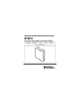
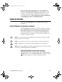
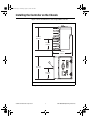
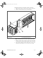
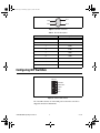
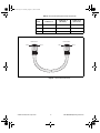
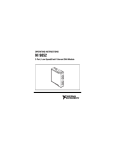
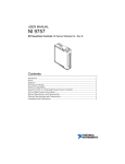
323561c.fm Page 1 Thursday, August 11, 2005 4:02 PM
OPERATING INSTRUCTIONS
CompactRIO cRIO-9002/9004
™
Intelligent Real-Time Embedded Controllers for CompactRIO
1
2
6
INPUT __
9–35 V --17 W MAX
3
5
1
2
3
LEDs
Power Connector
DIP Switches
4
4
5
6
Reset Button
RJ-45 Ethernet Port
RS-232 Serial Port
Figure 1. CompactRIO cRIO-9002/9004
323561c.fm Page 2 Thursday, August 11, 2005 4:02 PM
These operating instructions describe how to connect the National
Instruments cRIO-9002 and cRIO-9004 to a network and how to use
the features of the cRIO-9002 and cRIO-9004. For information about
installing, configuring, and programming the controller, refer to the
CompactRIO Bookshelf at Start»All Programs»National Instruments»
CompactRIO»Search the CompactRIO Bookshelf.
Safety Guidelines
Operate the cRIO-9002/9004 only as described in these operating
instructions.
Safety Guidelines for Hazardous Locations
The cRIO-9002/9004 is suitable for use in Class I, Division 2, Groups A,
B, C, and D hazardous locations; Class I, Zone 2, AEx nC IIC T4, and
Ex nC IIC T4 hazardous locations; and nonhazardous locations only.
Follow these guidelines if you are installing the cRIO-9002/9004 in a
potentially explosive environment. Not following these guidelines may
result in serious injury or death.
Caution Do not disconnect the power supply wires and connectors from the controller
unless power has been switched off.
Caution
Do not install or remove the controller unless power has been switched off.
Caution
Substitution of components may impair suitability for Class I, Division 2.
For Zone 2 applications, install the CompactRIO system in an enclosure rated to
at least IP 54 as defined by IEC 60529 and EN 60529.
Caution
Special Conditions for Safe Use in Europe
This equipment has been evaluated as EEx nC IIC T4 equipment under
DEMKO Certificate No. 03 ATEX 0324020X. Each controller is marked
II 3G and is suitable for use in Zone 2 hazardous locations.
cRIO-9002/9004 Operating Instructions
2
ni.com
323561c.fm Page 3 Thursday, August 11, 2005 4:02 PM
Installing the Controller on the Chassis
Figure 2 shows the dimensions of the CompactRIO controller.
90.2 mm
(3.55 in.)
44.2 mm
(1.74 in.)
77.3 mm
(3.04 in.)
1
88.1 mm
(3.47 in.)
44.2 mm
(1.74 in.)
1
M4 Thread
Figure 2. CompactRIO Controller, Front and Bottom Views with Dimensions
© National Instruments Corporation
3
cRIO-9002/9004 Operating Instructions
323561c.fm Page 4 Thursday, August 11, 2005 4:02 PM
Complete the following steps to install the controller on the chassis.
1.
Make sure that no power is connected to the controller or the chassis.
2.
Align the controller with the chassis as shown in Figure 3.
1
4
3
2
1
2
Controller
Captive Screws
3
4
Controller Slot
Reconfigurable Embedded Chassis
Figure 3. Installing the Controller on the Chassis (Eight-Slot Chassis Shown)
3.
Slide the controller onto the controller slot on the chassis. Press firmly
to ensure the chassis connector and the controller connector are mated.
4.
Using a number 2 Phillips screwdriver, tighten the two captive screws
on the front of the controller to 1.3 N · m (11.5 lb · in.) of torque.
cRIO-9002/9004 Operating Instructions
4
ni.com
323561c.fm Page 5 Thursday, August 11, 2005 4:02 PM
Connecting the Controller to a Network
Connect the controller to an Ethernet network using the RJ-45 Ethernet port
on the controller front panel. Use a standard Category 5 (CAT-5) Ethernet
cable to connect the controller to an Ethernet hub, or use an Ethernet
crossover cable to connect the controller directly to a computer.
To prevent data loss and to maintain the integrity of your Ethernet installation,
do not use a cable longer than 100 m. If you are using 100 Mbps Ethernet, National
Instruments recommends using a CAT-5 shielded twisted-pair Ethernet cable.
Caution
The host computer communicates with the controller over a standard
Ethernet connection. If the host computer is on a network, you must
configure the controller on the same subnet as the host computer. If neither
the host computer nor the CompactRIO controller is connected to a
network, you can connect the two directly using a CAT-5 crossover cable.
If you need to build your own cable, refer to the Cabling section for more
information about Ethernet cable wiring connections.
In order to configure the controller, you must connect it to the same subnet
as the host computer. If you want to use the controller on a subnet other than
the one the host computer is on, first connect the controller on the same
subnet as the host computer. Use DHCP to assign an IP address or reassign
a static IP address for the subnet where you want it to be and physically
move it to the other subnet. The first time you configure the controller, you
must also install software on it. Refer to the Measurement & Automation
Explorer Help for more information about configuring the controller in
Measurement & Automation Explorer (MAX). Contact your network
administrator if you need assistance configuring the host computer and
controller on the same subnet.
Wiring Power to the Controller
Caution You must install the controller on a CompactRIO chassis and tighten the captive
screws before you apply power to the controller. Installing the controller while power is
applied to it can cause damage to the chassis.
The controller requires an external power supply that meets the
specifications in the Power Requirements section. The controller filters and
regulates the supplied power and provides power for all of the I/O modules
in the chassis. You can connect two power sources to the controller. The
controller draws power from the power source with the higher voltage. The
controller has one layer of reversed-voltage protection. The power source
© National Instruments Corporation
5
cRIO-9002/9004 Operating Instructions
323561c.fm Page 6 Thursday, August 11, 2005 4:02 PM
you connect to the controller must provide an additional layer of
reversed-current flow protection. Complete the following steps to connect
power sources to the controller.
1.
Install a ferrite across the negative and positive wires for both the V1
and V2 terminals. Refer to Figure 4 for an illustration of this step.
2.
Connect the positive lead of one of the power sources to the
V1 terminal and the negative lead to one of the C terminals.
3.
Connect the positive lead of the other power source to the V2 terminal
and the negative lead to one of the C terminals.
The controller draws power from either V1 or V2 depending on which terminal has
a higher voltage. It does not draw power from both terminals.
Note
Caution The C terminals are internally connected to each other. Make sure to use
two power sources that have a common ground.
V1
C
V2
C
Figure 4. Wiring Power to the Controller
cRIO-9002/9004 Operating Instructions
6
ni.com
323561c.fm Page 7 Thursday, August 11, 2005 4:02 PM
Powering On the Controller
Plug in each power supply to the CompactRIO system. The controller runs
a power-on self test (POST). During the POST, the Power, Status, and
User1 LEDs turn on. The User1 and Status LEDs turn off, indicating that
the POST is complete. If the LEDs do not behave in this way when the
controller powers on, refer to the Understanding LED Indications section.
Boot Options
You can configure the controller to launch an embedded stand-alone
application each time you boot the controller. Refer to the LabVIEW
Real-Time Module User Manual for more information.
Table 1 lists the reset options available on CompactRIO backplanes, such
as the cRIO-910x devices. Use these options to determine how the
CompactRIO controllers, such as the cRIO-9002 and cRIO-9004
controllers, are reset in various conditions.
Table 1. CompactRIO Reset Options
Backplane Reset Option
Controller Behavior
Do Not Autoload on Reset
Does not load the FPGA bit stream
from flash memory
Autoload on Power-On Reset
Loads the FPGA bit stream from
flash memory to the FPGA when
the controller powers on.
Autoload on Any Device Reset
Loads the FPGA bit stream from
flash to the FPGA when you
reboot the controller either with or
without cycling power.
Connecting Serial Devices to the Controller
The controller has an RS-232 serial port to which you can connect devices
such as displays or input devices. Use the Serial VIs to read from and write
to the serial port. For more information about the Serial VIs, refer to the
LabVIEW Help.
© National Instruments Corporation
7
cRIO-9002/9004 Operating Instructions
323561c.fm Page 8 Thursday, August 11, 2005 4:02 PM
Pin 6
Pin 1
Pin 9
Pin 5
Figure 5. Controller Serial Port
Table 2. DB-9 Pin Descriptions
Pin
Signal
1
DCD
2
RXD
3
TXD
4
DTR
5
GND
6
DSR
7
RTS
8
CTS
9
RI
Configuring DIP Switches
ON OFF
SAFE MODE
CONSOLE OUT
IP RESET
NOAPP
USER1
Figure 6. Controller DIP Switches
All of the DIP switches are in the OFF position when the controller is
shipped from National Instruments.
cRIO-9002/9004 Operating Instructions
8
ni.com
323561c.fm Page 9 Thursday, August 11, 2005 4:02 PM
Safe Mode Switch
The position of the Safe Mode switch determines whether the embedded
LabVIEW Real-Time engine launches when the controller boots. If the
switch is in the OFF position, the LabVIEW Real-Time engine launches.
Keep this switch in the OFF position during normal operation. If the switch
is in the ON position when the controller boots, the controller launches only
the essential services required for updating its configuration and installing
software. The LabVIEW Real-Time engine does not launch.
Push the Safe Mode switch to the ON position if the software on the
controller is corrupted. If there is no software installed on the controller, the
controller automatically boots into safe mode regardless of the position of
the safe mode switch. The Safe Mode switch must be in the ON position to
reformat the drive on the controller. Refer to the Measurement &
Automation Explorer Help for more about installing software on a
controller and the reformatting the drive on the controller.
Console Out Switch
With a serial-port terminal program, you can use the Console Out switch to
read the IP address and BIOS version of the controller. Connect the serial
port on the controller to a computer. Push the switch to the ON position.
Make sure that the serial-port terminal program is configured to the
following settings:
•
9,600 bits per second
•
Eight data bits
•
No parity
•
One stop bit
The serial-port terminal program displays the IP address and BIOS version.
Keep this switch in the OFF position during normal operation.
IP Reset Switch
Push the IP Reset switch to the ON position and reboot the controller to
reset the IP address of the controller to 0.0.0.0. If the controller is on your
local subnet and the IP Reset switch is in the ON position, the controller
appears in MAX with IP address 0.0.0.0. You can configure a new
IP address for the controller in MAX. Refer to the Resetting the Network
Configuration of the Controller section for more information about
resetting the IP address. You also can push this switch to the ON position
to unlock a controller that was previously locked in MAX.
© National Instruments Corporation
9
cRIO-9002/9004 Operating Instructions
323561c.fm Page 10 Thursday, August 11, 2005 4:02 PM
No App Switch
Push the No App switch to the ON position to prevent a LabVIEW startup
application from running on the controller when the controller powers on.
If you want to permanently disable the application from running when the
controller powers on, you must disable it in LabVIEW. To run an
application when the controller powers on, push the No App switch to the
OFF position, create an application using the LabVIEW Application
Builder, and configure the application in LabVIEW to launch when the
controller powers on. If you already have an application configured to
launch when the controller powers on and you push the No App switch
from ON to OFF, the power-on application is automatically enabled. For
more information about automatically launching VIs when the controller
powers on and disabling VIs from launching when the controller powers
on, refer to the LabVIEW Real-Time Module User Manual.
User1 Switch
You can define the behavior of the User1 switch for your application. To
define the behavior of this switch in your embedded application, use the
RT Read Switch VI in your LabVIEW RT embedded VI. For more
information about the RT Read Switch VI, refer to the LabVIEW Help.
Understanding LED Indications
POWER
BACKUP
STATUS
USER1
Figure 7. CompactRIO Controller LEDs
Power LED
The Power LED is lit while the controller is powered on. This LED
indicates that the power supply connected to the controller is adequate,
and that the controller is supplying power to the CompactRIO system.
Backup LED
The Backup LED is lit when the controller is drawing power from the
V2 terminal.
cRIO-9002/9004 Operating Instructions
10
ni.com
323561c.fm Page 11 Thursday, August 11, 2005 4:02 PM
Status LED
The Status LED is off during normal operation. The controller indicates
specific error conditions by flashing the Status LED a certain number of
times as shown in Table 3.
Table 3. Status LED Indications
Number of
Flashes
Indication
Slow, continuous
flashing
(one flash every
couple seconds)
The controller is unconfigured. Use MAX to
configure the controller. Refer to the Measurement
& Automation Explorer Help for information about
configuring the controller.
2
The controller has detected an error in its software.
This usually occurs when an attempt to upgrade the
software is interrupted. Reinstall software on the
controller. Refer to the Measurement & Automation
Explorer Help for information about installing
software on the controller.
3
The controller is in safe mode because the Safe
Mode DIP switch is in the ON position. Refer to the
Configuring DIP Switches section for information
about the Safe Mode DIP switch.
4
The controller software has crashed twice without
rebooting or cycling power between crashes. This
usually occurs when the controller runs out of
memory. Review your RT VI and check the
controller memory usage. Modify the VI as
necessary to solve the memory usage issue.
Continuous
flashing
The controller has detected an unrecoverable error.
Contact National Instruments.
Continuously lit
The flash memory card on the controller is corrupt.
Reformat the hard drive on the controller. Refer to
Measurement & Automation Explorer Help for
more information about reformatting the hard drive.
User1 LED
You can define the User1 LED to meet the needs of your application. To
define the LED, use the RT LEDs VI in LabVIEW. For more information
about the RT LEDs VI, refer to the LabVIEW Help.
© National Instruments Corporation
11
cRIO-9002/9004 Operating Instructions
323561c.fm Page 12 Thursday, August 11, 2005 4:02 PM
Resetting the Network Configuration of the Controller
If the controller is not able to communicate with the network, you can
manually restore the unit to the factory network settings. When you reset
the controller, the IP address, subnet mask, DNS address, gateway, and
Time Server IP are set to 0.0.0.0. Resetting does not affect power-on
defaults, watchdog settings, or VIs.
Complete the following steps to reset the controller.
1.
Move the IP Reset DIP switch to the ON position.
2.
Push the Reset button to cycle power to the controller. The Status LED
flashes once, indicating that the controller IP address is unconfigured.
3.
Move the IP Reset switch to the OFF position.
The controller settings are reset. You can reconfigure the settings in MAX
from a computer on the same subnet. Refer to the Measurement &
Automation Explorer Help for more information about configuring the
controller.
Specifications
The following specifications are typical for the range –40 to 70 °C
unless otherwise noted.
Network
Network interface ...................................10BaseT and 100BaseTX
Ethernet
Compatibility ..........................................IEEE 802.3
Communication rates ..............................10 Mbps, 100 Mbps,
auto-negotiated
Maximum cabling distance.....................100 m/segment
Memory
cRIO-9002
Nonvolatile ......................................64 MB
DRAM .............................................32 MB
cRIO-9004
Nonvolatile ......................................512 MB
DRAM .............................................64 MB
cRIO-9002/9004 Operating Instructions
12
ni.com
323561c.fm Page 13 Thursday, August 11, 2005 4:02 PM
MTBF
The following MTBF specifications apply to the cRIO-9002 and
cRIO-9004.
MTBF..................................................... 1,253,788 hours at 25 °C;
Bellcore Issue 6, Method 1,
Case 3, Parts Count Method
Note Contact NI for Bellcore MTBF specifications at other temperatures or for
MIL-HDBK-217F specifications. Go to ni.com/certification and search by model
number or product line for more information about MTBF and other product certifications.
Power Requirements
You must use a National Electric Code (NEC) Class 2 power source with
the cRIO-9002/9004.
Recommended power supply ................. 48 W secondary,
18 VDC to 24 VDC
Power consumption
Controller only ................................ 7 W max
Controller supplying power to
8 CompactRIO modules.................. 17 W
Power supply
On power up.................................... 9 to 35 V
After power up ................................ 6 to 35 V
The cRIO-9002 and cRIO-9004 power up only at 9 V or higher, but when these
devices are powered on, they can run on as little as 6 V.
Note
Physical Characteristics
If you need to clean the controller, wipe it with a dry towel.
Screw-terminal wiring............................ 12 to 24 AWG copper conductor
wire with 10 mm (0.39 in.) of
insulation stripped from the end
Torque for screw terminals .................... 0.5 to 0.6 N · m
(4.4 to 5.3 lb · in.)
Weight .................................................... Approx. 488 g (17.2 oz)
© National Instruments Corporation
13
cRIO-9002/9004 Operating Instructions
323561c.fm Page 14 Thursday, August 11, 2005 4:02 PM
Safety
Safety Voltages
Connect only voltages that are within these limits.
V to C......................................................35 V max, Measurement
Category I
Measurement Category I is for measurements performed on circuits not
directly connected to the electrical distribution system referred to as
MAINS voltage. MAINS is a hazardous live electrical supply system that
powers equipment. This category is for measurements of voltages from
specially protected secondary circuits. Such voltage measurements include
signal levels, special equipment, limited-energy parts of equipment,
circuits powered by regulated low-voltage sources, and electronics.
Caution Do not connect V and C terminals to signals within Measurement Categories II,
III, or IV.
Safety Standards
The cRIO-9002/9004 is designed to meet the requirements of the following
standards of safety for electrical equipment for measurement, control, and
laboratory use:
•
EN 61010-1, IEC 61010-1
•
UL 61010-1
•
CAN/CSA-C22.2 No. 61010-1
Note For UL and other safety certifications, refer to the product label, or visit
ni.com/certification, search by model number or product line, and click the
appropriate link in the Certification column.
Hazardous Locations
U.S. (UL) ................................................Class I, Division 2, Groups A,
B, C, D, T4; Class I, Zone 2,
AEx nC IIC T4
Canada (C-UL) .......................................Class I, Division 2, Groups A,
B, C, D, T4; Class I, Zone 2,
Ex nC IIC T4
Europe (DEMKO) ..................................EEx nC IIC T4
cRIO-9002/9004 Operating Instructions
14
ni.com
323561c.fm Page 15 Thursday, August 11, 2005 4:02 PM
Environmental
The cRIO-9002/9004 is intended for indoor use only. For outdoor use,
mount the CompactRIO system in a suitably rated enclosure.
Operating temperature
(IEC 60068-2-1, IEC 60068-2-2) ................ –40 to 70 °C
To meet this operating temperature range, follow the guidelines in the installation
instructions for your CompactRIO system.
Note
Storage temperature
(IEC 60068-2-1, IEC 60068-2-2) ................ –40 to 85 °C
Ingress protection ................................... IP 40
Operating humidity
(IEC 60068-2-56) ...................................... 10 to 90% RH, noncondensing
Storage humidity
(IEC 60068-2-56) ...................................... 5 to 95% RH, noncondensing
Maximum altitude .................................. 2,000 m
Pollution Degree (IEC 60664) ............... 2
Shock and Vibration
To meet these specifications, you must panel mount the CompactRIO
system and affix ferrules to the end of the terminal wires.
Operating vibration,
random (IEC 60068-2-64)...................... 5 grms, 10 to 500 Hz
Operating shock
(IEC 60068-2-27) ................................... 30 g, 11 ms half sine
50 g, 3 ms half sine,
18 shocks at 6 orientations
Operating vibration,
sinusoidal (IEC 60068-2-6).................... 5 g, 10 to 500 Hz
© National Instruments Corporation
15
cRIO-9002/9004 Operating Instructions
323561c.fm Page 16 Thursday, August 11, 2005 4:02 PM
Electromagnetic Compatibility
Emissions................................................EN 55011 Class A at 10 m
FCC Part 15A above 1 GHz
Immunity ................................................Industrial levels per
EN 61326:1997 + A2:2001,
Table A.1
EMC/EMI ...............................................CE, C-Tick, and FCC Part 15
(Class A) Compliant
Note
For EMC compliance, operate this device with shielded cabling.
CE Compliance
This product meets the essential requirements of applicable European
directives, as amended for CE marking, as follows:
Low-Voltage Directive (safety)..............73/23/EEC
Electromagnetic Compatibility
Directive (EMC) .....................................89/336/EEC
Refer to the Declaration of Conformity (DoC) for this product for any additional
regulatory compliance information. To obtain the DoC for this product, visit
ni.com/certification, search by model number or product line, and click the
appropriate link in the Certification column.
Note
Cabling
Table 4 shows the standard Ethernet cable wiring connections for both
normal and crossover cables.
Table 4. Ethernet Cable Wiring Connections
Pin
cRIO-9002/9004 Operating Instructions
Connector 1
Connector 2
(Normal)
Connector 2
(Crossover)
1
white/orange
white/orange
white/green
2
orange
orange
green
3
white/green
white/green
white/orange
4
blue
blue
blue
5
white/blue
white/blue
white/blue
16
ni.com
323561c.fm Page 17 Thursday, August 11, 2005 4:02 PM
Table 4. Ethernet Cable Wiring Connections (Continued)
Pin
Connector 1
Connector 2
(Normal)
6
green
green
orange
7
white/brown
white/brown
white/brown
8
brown
brown
brown
Connector 1
Pin 1
Connector 2
(Crossover)
Connector 2
Pin 8
Pin 1
Pin 8
Figure 8. Ethernet Connector Pinout
© National Instruments Corporation
17
cRIO-9002/9004 Operating Instructions
323561c.fm Page 18 Thursday, August 11, 2005 4:02 PM
National Instruments Contact Information
National Instruments corporate headquarters is located at 11500 North
Mopac Expressway, Austin, Texas, 78759-3504. National Instruments also
has offices located around the world to help address your support needs.
For telephone support in the United States, create a service request at
ni.com/support and follow the calling instructions or dial 512 795 8248.
For telephone support outside the United States, contact your local branch
office:
Australia 1800 300 800, Austria 43 0 662 45 79 90 0,
Belgium 32 0 2 757 00 20, Brazil 55 11 3262 3599,
Canada 800 433 3488, China 86 21 6555 7838,
Czech Republic 420 224 235 774, Denmark 45 45 76 26 00,
Finland 385 0 9 725 725 11, France 33 0 1 48 14 24 24,
Germany 49 0 89 741 31 30, India 91 80 51190000,
Israel 972 0 3 6393737, Italy 39 02 413091, Japan 81 3 5472 2970,
Korea 82 02 3451 3400, Lebanon 961 0 1 33 28 28,
Malaysia 1800 887710, Mexico 01 800 010 0793,
Netherlands 31 0 348 433 466, New Zealand 0800 553 322,
Norway 47 0 66 90 76 60, Poland 48 22 3390150,
Portugal 351 210 311 210, Russia 7 095 783 68 51,
Singapore 1800 226 5886, Slovenia 386 3 425 4200,
South Africa 27 0 11 805 8197, Spain 34 91 640 0085,
Sweden 46 0 8 587 895 00, Switzerland 41 56 200 51 51,
Taiwan 886 02 2377 2222, Thailand 662 278 6777,
United Kingdom 44 0 1635 523545
cRIO-9002/9004 Operating Instructions
18
ni.com
323561c.fm Page 20 Thursday, August 11, 2005 4:02 PM
National Instruments, NI, ni.com, and LabVIEW are trademarks of National Instruments Corporation.
Refer to the Terms of Use section on ni.com/legal for more information about National
Instruments trademarks. Other product and company names mentioned herein are trademarks or trade
names of their respective companies. For patents covering National Instruments products, refer to the
appropriate location: Help»Patents in your software, the patents.txt file on your CD, or
ni.com/patents.
© 2004–2005 National Instruments Corporation. All rights reserved.
373561C-01
Aug05


![[c]FP-DO-401 Operating Instructions](http://vs1.manualzilla.com/store/data/005693758_1-4b10a2df6965457ee651014d1377996a-150x150.png)