1
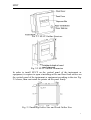
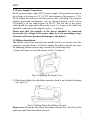
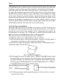
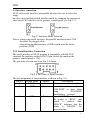
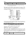
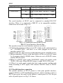
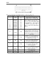
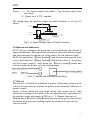
SPRT
R
SP-CF Series
High Speed Dot-matrix
Micro Printer
User’s Manual
Beijing Spirit Technology
Development Co, Ltd.
SPRT
Content
Introduction·························································································· 2
Chapter 1 Feature and Performance··················································· 3
1.1 Print Performance and Model ·········································· 3
1.2 Print Paper ······································································· 3
1.3 Ribbon ············································································· 3
1.4 Print Font········································································· 3
1.5 Print Control Commands ················································· 3
1.6 Interface··········································································· 4
1.7 Power Supply··································································· 4
1.8 Outline Dimension··························································· 4
1.9 Weight ············································································· 4
2.0 Operation Environment···················································· 4
Chapter 2 System Installation and Operation····································· 4
2.1 Installation Method·························································· 4
2.2 Power Supply Connection················································ 6
2.3 Ribbon Installation··························································· 6
2.4 Printer Installation ··························································· 7
2.5 Interface Connection························································ 8
2.5.1 Serial Interface Connection·············································· 8
2.5.2 Parallel Interface Connection········································· 10
2.6 Buttons and Indicators ··················································· 12
2.5 Self-test·········································································· 12
Chapter 3 Print Control Commands················································· 13
3.1 Summary ······································································· 13
3.2 Paper Feed Commands ·················································· 13
3.3 Format Setting Commands ············································ 15
3.4 Character Setting Commands········································· 19
3.5 User-defined Character Setting Commands ··················· 23
3.6 Graphics Print Commands ············································· 25
3.7 Initialization Commands················································ 27
3.8 Data Control Commands················································ 28
3.9 Hexadecimal Print Commands······································· 28
3.10 Chinese Print Control Commands··································· 29
Appendix 1 Performance Index ·························································· 31
Appendix 2 Index of Print Commands ··············································· 32
1
SPRT
Introduction
SP-CF series high speed panel micro printers adopt high speed impact
dot-matrix print, new type panel structure, they especially suitable for
being installed on the vertical panel of the instruments and equipments,
become an organic whole with the instrument and equipment.
The structure of SP-CF printers are reasonable in design, they are
convenient to change paper and have the function of testing paper running
out; There are serial interface and parallel interface in the printers for users
to select for use; they are installed inside GB Chinese character library
level I, II, can realize high speed print for Chinese characters.
SP-CF printers are complete in specifications and function, simple to
operate, convenient to maintain, are extensively suitable for the measuring
instrument, record device, cash register equipment etc..
2
SPRT
Chapter 1 Feature and Performance
1.1 Print Performance and Model
* Print method: impact dot-matrix
* Copy capability: 1 (original) +1
* Model: SP-CF support EPSON M-180, M-190 and M-160 series ten
kinds of print heads, the main models are:
Model
Print
Head
SP-CF24 M-190
SP-CF40 M-192
Character Print
Print
Speed
Density
(5×7)
(line/sec.
(dot/line)
24
40
2.5
1.5
144
240
Reliability(line)
MCBF
Interface
1.5×10⁶
1.0×10⁶
Serial/Parallel
Serial/Parallel
1.2 Print Paper
* Common paper roll, outer diameter (max.) 50mm, inner diameter
12.5mm, paper width: 57.5±0.5mm, paper weight: 53~64g/m2
1.3 Ribbon
* ERC-09: cassette, purple, life: 25 million characters
* ERC-22: cassette, purple, life: 100 million characters
1.4 Print Font
* 96 ASCII characters, 352 other characters;
* Greek, German, Russian, French etc. letters;
* Japanese katakana, partial 5×7 dots Chinese characters;
* Mathematics symbols, print symbols, graphics symbols;
* 32 user-defined characters;
* Standard characters are 5×7 dots, graphics symbols and user-defined
characters are 6×8 dots;
* Chinese Characters: GB level 1, 2, 15×16 dots.
1.5 Print Control Commands
* 40 general ESC/P print control commands and FS Chinese character print
control commands.
* Character, bit-map graphics print command
* FSC/P commands support character print and its enlargement, up-line
and underline; and the print of bit-map graphics, user-defined character,
can realize print format setting, hexadecimal mode print etc.
* Chinese character print command
FS commands support inside GB level 1, 2 hard Chinese character set,
3
SPRT
Chinese character, Roman letters (A6 area) and tabs print (A9 area),
detailed commands please refer to Chapter 3 “print control command”.
1.6 Interface
* Serial interface (compatible with RS-232C)
Baud rate: 1200/2400/4800/9600bps, selected by DIP switch;
Handshaking protocol: RTS/CTS or XON/XOFF protocol, selected by
DIP switch;
Interface socket: IDC 10-pin socket;
Signal level: EIA
* Parallel interface (compatible with 8-bit print parallel interface)
Handshaking protocol: BUSY or ACK protocol;
Interface socket: IDC 26-pin socket;
Signal level: TTL
1.7 Power Supply
* MOLEX-5045-3 model socket, DC5V±5%, average current 3A, peak
value current 5A.
1.8 Outline Dimension
* 122 (W) ×90 (D) ×129 (H) mm
1.9 Weight
* About 350g (excluding paper roll)
1.10 Operation Environment
* Operation temperature: 0~40℃;
* Relative humidity: 5~85%
Chapter 2 System Installation and Operation
2.1 Installation Method
The outline structure of SP-CF printer is as Fig. 2-1 shows, the outline
dimension is as Fig.2-2 shows:
4
SPRT
Fig. 2-1 SP-CF Outline Structure
Fig. 2-2 SP-CF Outline Dimension
In order to install SP-CF on the vertical panel of the instrument or
equipment, it requires to open a installing orifice and four fixed orifices on
the vertical panel of the instrument or equipment according to the size Fig.
2-3 shows, then can install the printer on the panel firmly:
Fig. 2-3 Installing Orifice Size and Fixed Orifice Size
5
SPRT
2.2 Power Supply Connection
SP-CF printer adopts single DC5V power supply. The permission range of
the voltage of the power is 5V±0.25V, the tolerance of the power is ≥3A.
SP-CF printer has offered a two-line power cable with plug. The plug has
polarity protection mechanisms, can be inserted directly in the socket
CN1which is on the control panel of SP-CF. The red line of the power
cable should be connected to the positive pole (+) of power, the white line
should be connected to the negative pole (–) of power.
Please note that the polarity of the power shouldn't be connected
incorrectly, the voltage of the power must be in the permitting range,
otherwise will cause permanent damage to the printer.
2.3 Ribbon Installation
The ribbon cassette has already been installed well at ex-factory, but after
using for a period of time, it needs to change the ribbon cassette, the ways
for changing ribbon cassette may accord to the following steps:
(1)Open the front cover of the printer as Fig. 2-4 shows;
Fig.2-4 Opening the Front Cover
(2)Take down lightly the old ribbon cassette which is on the head of printer,
(see Fig.2-5).
Fig.2-5 Taking Down the Ribbon Cassette
Please note: lift up the left end of the ribbon cassette first, then lift up the
right one, take down the ribbon cassette.
6
SPRT
(3)Installing the new ribbon cassette: firstly put down gently the right end
of ribbon cassette on the gear wheel which is on the left end of the print
head, lift up the left end a little, don't put down , at this time if you find
the right end of ribbon cassette has not been put down to the bottom, please
hold down the knob of ribbon cassette with finger, rotate slightly according
to the arrow direction, until the ribbon cassette has been put down to the
bottom then put down the left end, please check the ribbon, if it hasn’t been
drawn to be straight or appeared to be out of the ribbon cassette, you can
rotate the knob which is on the ribbon cassette again, until draw the ribbon
in the ribbon cassette, then close the cover of the printer.
2.4 Print Paper Installation
The paper has already been installed at ex-factory for SP-CF printer, but
the paper head has not been inserted in the print head, this is in order to
prevent the print head from damage while transporting the printer for
long-distance or storing it for a long time, so must insert the head of the
paper roll in the print head firstly before using the printer.
The general steps of installing the paper are as follows:
(1) Open the front cover of the printer as Fig. 2-4 shows;
(2) Take down the paper roller from the printer, if there is already paper in
the printer, can jump over this step to the fourth step;
(3) Put the new paper on the paper roller, and insert it in the paper-in slot.
(4)Cut the paper end like Fig.2-6
Fig. 2-6 Paper End Sample
(5)Put through the power of printer, press 【Paper Feeding】button, make
the print head to turn, and insert the end of paper into the paper-in slot
by hand and make sure that the paper end appears from above the print
head, the paper should appear for a certain length, then press 【Paper
Feeding】button again or turn off the power.
(6) Pull the print paper out through the paper-out slot on front cover and
then close the cover.
7
SPRT
2.5 Interface connection
SP-CF offer serial interface and parallel interface for user to select for
using,
the user can select the needed interface mode by changing the position of
short circuit W3 which is on the printers’ control panel (see Fig.2-7).
Fig.2-7 Interface Mode Selection
Notice: when using serial interface, the parallel interface socket CN4
shouldn’t be plugged cable;
when using parallel interface, all DIP switch must be on the
position of OFF.
2.5.1 Serial Interface Connection
The serial interface of SP-CF printers is compatible with RS-232C
standard, the interface socket is IDC10-pin socket, the mark on the
printers’ control panel is CN3.
The pin order of serial port is as Fig. 2-8 shows:
Fig.2-8 Pin Order of Serial Interface
The pin assignment of serial interface is shown in Fig. 2-9:
Pin No. Signal Name
Source
Description
3
RXD
Host
Printer receives data from host
5
TXD
Printer
4
RTS
Printer
Printer transmits control code
XON/XOFF to host when
using
XON/XOFF
handshaking protocol
Signal “MARK” indicates that
the printer is “BUSY” and
unable to receive data;
“SPACE” indicates that the
printer is “READY” for
receiving data.
8
SPRT
GND
—
Signal Ground
Fig. 2-9
Pin Assignment of Serial Interface
Notice: (1) The “Source” denotes the source that signal come from;
(2) Logical signal level is EIA.
9
The baud rate in serial interface mode is optional in the range of 1200,
2400, 4800, 9600 bps, and is set by DIP switch on the control panel. You
can select suitable baud rate according to Fig.2-10. It has set the baud rate
to 9600bps at ex-factory.
Fig. 2-10 DIP Switch Setting
The data structure of serial interface is as Fig.2-11 shows, the structure can
be selected through DIP switch K4, K5 and K6. As shown in Fig.2-10, it is
set to 8-bit no parity at ex-factory.
Start Bit
Data Bit
Parity Bit
Stop Bit
1 bit
7 or 8 bits
1 bit
1 bit
Fig.2-11 Data Structure of Serial Interface
The polarity of RS-232 signal in serial interface mode is:
MARK=logic “1” (EIA-3V -12V low signal level)
SPACE=logic “0” (EIA+3V +12V high signal level)
There are two kinds of handshaking mode for selection, one is mark
control mode, another is XON/XOFF protocol mode, they can be selected
by DIP switch K3, as Fig.2-10 shows. It is set to XON/XOFF protocol
mode. The description for the two kinds of handshaking mode is as
Fig.2-12 shows.
Handshaking
Data
RS-232C Interface Signal
Mode
Direction
9
SPRT
Mark Control
XON/XOFF
4th signal line (RTS) is SPACE status
4th signal line (RTS) is MARK status
Send X-ON code 11H on 5th signal
line
Out
Send XOFF code 13H on 5th signal
line
Fig.2-12 Two Kinds of Handshaking Mode
In
Out
In
The serial interface of SP-CF can be connected to standard RS-232C
interface. When it is connected to IBM PC or its compatible machine,
connection can accord to Fig.2-13.
Fig.2-13 Connection between SP-CF and
IBM PC Serial Interface Sketch Map
The operation steps for serial interface mode are as below:
(1)Confirm the position of short circuit W3 which on the control panel is
on “ CONNECTION”, and there is no cable plugged on the serial
interface socket CN4;
(2)Select baud rate, data structure and handshaking mode with DIP switch;
(3)When remaining 32 bytes in the data buffer, will be set to BUSY status
by the printer, namely MARK status. Otherwise set to READY status,
namely SPACE status;
(4)When it is BUSY status under XON/XOFF control, the printer sends
XOFF (13H) code. When READY status, it sends XON (11H) code;
(5) When it is under mark control, the host sends or stops sending code
string according to RTS signal, RTS denotes READY status or BUSY
status.
2.5.2 Parallel interface connection
The parallel interface of SP-CF printer is 8-bit print parallel interface,
supports BUSY or ACK handshaking protocol, and its interface socket is
IDC26-pin socket, the mark on the printers’ control panel is CN4, the pin
order of parallel port is as Fig. 2-14 shows:
10
SPRT
Fig.2-14 Pin Order of Parallel Port
The pin assignment of parallel interface is shown in Fig. 3-2:
Pin No.
Signal
Direction
Description
Strobe pulse to latch data,
1
/STB
In
reading occurs at falling edge.
In
DATA1
3
These signals represent the 1st
In
DATA2
5
bit to 8th bit of the parallel data
In
DATA3
7
representatively, each signal is
In
DATA4
9
at HIGH level when data is
In
DATA5
11
logic 1, and LOW when data is
In
DATA6
13
logic 0.
In
DATA7
15
In
DATA8
17
Answering pulse, LOW level
signal indicates that data have
19
Out
already been received and the
/ACK
printer gets ready to receive the
next data.
HIGH level signal indicates
21
BUSY
Out
that the printer is BUSY and
can not receive data.
23
25
4
2,6,8,26
10-24
HIGH level signal indicates
that paper is running out.
Pulling up to HIGH level signal
SEL
Out
by a resistor indicates the
printer is on-line.
Pulling up to HIGH level signal
Out
by a resistor indicates that
/ERR
there is no error.
NC
--No connection
GND
--Grounding logical 0 level
Fig.2-15 Pin Assignment of Parallel Interface
PE
Out
11
SPRT
Notice: (1)“In” denotes input to the printer,“Out” denotes output from
the printer.
(2)Signal level is TTL standard.
The timing chart for interface signal of parallel interface is as Fig.2-16
shows:
BU SY
/A CK
DA TA
/S TB
0. 5μS
0. 5μS
0. 5μS
0. 5μS
0. 5μS
Fig.2-16 Signal Timing Chart of Parallel Interface
2.6 Buttons and Indicators
SP-CF has two indicators, the green one is power indicator, the red one is
paper-end indicator. When the printer powers on, the power indicator lights,
and when the paper is running out in the printer, the red indicator lights.
SP-CF has one button 【Paper Feeding】(can be seen when open the front
cover), hold down the 【Paper Feeding】button then release it, the printer
will feed paper emptily, hold down the 【Paper Feeding】button and
release it again, the printer will stop feeding paper.
Fig.2-17 Button and Indicator Sketch Map
2.7 Self-test
The self-test will check the condition of printer, if the printer prints out the
self-test receipt correctly, it means the printer works normally. Otherwise it
needs to repair.
Firstly, self-test prints out print head model, then prints out all valid
characters according to the order of the two character sets, later prints out
the interface mode and sample of GB level 1, 2 Chinese character set.
Holding down 【Paper Feeding】button and turn on the power, then release
the button when the paper feeding begins, the printer will print out the
self-test receipt.
12
SPRT
Chapter 3 Print Control commands
3.1 Summary
SP-CF offer more than 40 kinds of print control commands, these
commands specify the following function of the printer:
(1)Define format;
(2)Enlarge or diminish characters;
(3)Print bit map graphics;
(4)Select character set;
(5)Define user-defined characters;
(6)Other.
These commands include one-byte control codes or ESC control code
sequences and FS control code sequences. ESC control code sequences are
begun with “ESC” code and followed by other character codes; FS control
code sequences are begun with “FS” code and followed by other character
codes.
The control codes of the printer are not standardized, every printer
manufacturer has his own a set of control code system. The control codes
of SP-CF are designed referring to the fashionable ones of IBM and
EPSON printer. So, they are compatible with most of printers.
Each command is described in following format:
Command name
Function
Format:
ASCII: the standard ASCII character sequence
Decimal: the Decimal number sequence
Hexadecimal: the Hexadecimal number sequence
Explanation: what the command does and how to use it.
Example: some examples are listed to illustrate the command for better
understanding.
The following is the description of each command according to the
function of each command.
3.2 Paper Feeding Commands
LF
Feed Line
Format: ASCII:
LF
Decimal:
10
Hexadecimal: 0A
Explanation:
Print the content in the buffer and feed paper one line. Only feed paper one
line if buffer is empty.
13
SPRT
ESC J
Format:
n Dot Line Feed
ESC 1
Format:
Set n Dot-line Spacing
FF
Format:
Feed Page
ASCII:
ESC
J
n
Decimal:
27
74
n
Hexadecimal: 1B
4A
n
Explanation:
The printer feeds paper n dot lines. n=0~255.
If there remains data that have not been printed, print these data before
feeding paper.
If you need to feed paper immediately but no carriage return, can use ESC
J command. Line spacing will be adjusted automatically when using
commands ESC V and ESC W for enlarge characters.
ASCII:
ESC
1
n
Decimal:
27
49
n
Hexadecimal: 1B
31
n
Explanation:
The line spacing is set to n dot-lines for future Line Feed command.
n=0~255, default setting n=3 for text printing, n=0 for bit map printing
when using ESC K command.
The BASIC programs for observing the effect of this command are as
below:
10 FOR I= 1 TO 11 STEP 2
20 LPRINT CHR$ (27); “1”; CHR$ (I)
’ESC 1, set line spacing
30 LPRINT “LINESPACING”; CHR$ (10)
’Print character string and
feed line
40 NEXT I
The print result of the said programs in SP-CF24 is as following:
ASCII:
FF
Decimal:
12
Hexadecimal: 0C
Explanation:
Feed paper to the beginning of the next page.
14
SPRT
3.3 Format Setting Commands
ESC C
Set Page Length
Format: ASCII:
ESC
C
n
Decimal:
27
67
n
Hexadecimal: 1B
43
n
Explanation:
The page length is set to n character lines. n=0~255, when n=0, the page
length is 256 lines. Default n=40.
ESC N
Format:
Set Binding Length
ESC O
Format:
Cancel Binding Length
ESC B
Format:
Set Vertical Tab Value
n1 n2 n3…NUL
n1 n2 n3…0
n1 n2 n3…00
ASCII:
ESC
N
n
Decimal:
27
78
n
Hexadecimal: 1B
4E
n
Explanation:
The binding length is set to n lines. n=0~255, default n= 0. In SP-A,
binding length denotes the number of blank line between one page and the
next page.
Example: set binding length to 3 lines, send the following sequence to the
printer:
ASCII:
ESC
N
ETX
Decimal:
27
78
3
Hexadecimal: 1B
4E
03
The BASIC programs for sending the said sequence are as below:
LPRINT CHR$(27);“N”; CHR$ (3)
ASCII:
ESC
O
Decimal:
27
79
Hexadecimal: 1B
4F
Explanation:
The binding length is set to 0 line, it means the printer will print
line-by-line, won’t vacate blank lines between each page.
ASCII:
ESC
B
Decimal:
27
66
Hexadecimal: 1B
42
Explanation:
The tab positions are entered as n1, n2 and so on, all of these should be
within the page length set by ESC C command.
Command NUL added at the end indicates the command is over.
15
SPRT
All vertical tab positions that input can be deleted by using this command
in ESC B NUL format.
VT command is to carry out vertical tab, the paper fed to the next vertical
position.
Example: set three vertical tab values at 2nd line, 5th line, 8th line in one
page, you can send the following commands:
ASCII:
ESC
B
STX
ENQ
BS
NUL
Decimal:
27
66
2
5
8
0
Hexadecimal: 1B
42
02
05
08
00
The BASIC programs for this example are as below:
10 LPRINT CHR$ (27); “B”; CHR$ (2); CHR$ (5); CHR$ (8); CHR$
(0);
’ESC B command
20 LPRINT
CHR$ (11);
’VT command
30 LPRINT
“VTAB1”;
’Print character string
40 LPRINT
CHR$ (11);
’ VT command
50 LPRINT
“VTAB2”;
’Print character string
60 LPRINT
CHR$ (11);
’ VT command
70 LPRINT
“VTAB3”;
’Print character string
The print result in SP-CF24 is as following:
VT
Format:
Carry out Vertical Tab Value
ESC D
Format:
Set Horizontal Tab Value
n1 n2 n3…NUL
n1 n2 n3…0
n1 n2 n3…00
ASCII:
VT
Decimal:
11
Hexadecimal: 0B
Explanation:
Feed paper to the next vertical tab position which is set by ESC B
command.
Notice: if there is no vertical tab value setting, or the current position
equals or is beyond the last vertical tab position, VT command is to feed
paper one line only (same to LF command).
ASCII:
ESC
Decimal:
27
Hexadecimal: 1B
D
68
44
16
SPRT
Explanation:
The tab positions are entered as n1, n2 and so on, all of these should be
within the line width of this model printer. (Refer to 1.1)
Command NUL added at the end indicates the command is over.
All horizontal tab positions that set can be deleted by using this command
in ESC D NUL format.
HT command is to carry out horizontal tab.
Example: set three horizontal tab values at 2nd, 9th line, 14th character
position in one line, you can send the following commands:
ASCII:
ESC
D
STX
HT
SO
NUL
Decimal:
27
68
2
9
14
0
Hexadecimal: 1B
44
02
09
0E
00
The BASIC programs for this example are as below:
10 LPRINT “1234567890123456”
’Ruler
20 LPRINT CHR$ (27); “D”; CHR$ (2); CHR$ (9); CHR$ (14); CHR$
(0); ’ESC D command
30 LPRINT
CHR$ (9);
’HT command
40 LPRINT
“HT1”;
’Print character string
50 LPRINT
CHR$ (9);
’ HT command
60 LPRINT
“HT2”;
’Print character string
70 LPRINT
CHR$ (9);
’ HT command
80 LPRINT
“HT3”;
’Print character string
The print result in SP-CF24 is as following:
HT
Format:
Carry out Horizontal Tab Value
ESC f
Format:
Print Blank Characters or Lines
m
n
m
n
m
n
ASCII:
HT
Decimal:
9
Hexadecimal: 09
Explanation:
The print position is advanced to the next horizontal tab position which is
set by ESC D command.
If there is no horizontal tab value setting, or the current position equals or
is beyond the last horizontal tab position, HT command won’t be carried
out.
ASCII:
ESC
Decimal:
27
Hexadecimal: 1B
f
102
66
17
SPRT
Explanation:
When m=0, ESC f NUL n will command to print n blank characters, the
value of n should be within the line width of this model printer. (Refer to
1.1)
When m=1, ESC f SOH n will command to print n blank lines. n=0~255.
Example: print 6 blank characters in one line, you can send the following
commands:
ASCII:
ESC
f
NUL
ACK
Decimal:
27
102
0
6
Hexadecimal: 1B
66
00
06
Another example: print 6 blank lines, you can send the following
commands:
ASCII:
ESC
F
SOH
CK
Decimal:
27
102
1
6
Hexadecimal: 1B
66
01
06
ESC Q
Format:
Set Right Margin
ASCII:
ESC
Q
n
Decimal:
27
81
n
Hexadecimal: 1B
51
n
Explanation:
The value of n should be in the range from 0 to the line width of this model
printer. (Refer to 1.1)
Default n=0, that means no right margin.
This command sets absolute position, and won’t be influenced by character
enlarging commands ESC U and ESC W.
After setting this command, the printer will carry out carriage return and
feed line as long as the right margin position is reached.
Example: set right margin value to 6, you can send the following
commands:
The BASIC programs for this example are as below:
10
LPRINT “123456789012345678901234”
20
LPRINT
CHR$ (27); “Q”; CHR$ (6); ’ESC Q command
30
LPRINT “1234567890123456789012345678901234567890”
The print result in SP-CF24 is as following:
18
SPRT
ESC 1
Format:
Set Left Margin
ASCII:
ESC
1
n
Decimal:
27
108
n
Hexadecimal:
1B
6C
n
Explanation:
The value of n should be in the range from 0 to the line width of this model
printer.
Default n=0, that means no left margin.
This command sets absolute position, and won’t be influenced by character
enlarging commands ESC U and ESC W.
Example: set left margin value to 6, you can send the following commands:
ASCII:
ESC
1
ACK
Decimal:
27
108
6
Hexadecimal: 1B
6C
06
The BASIC programs for this example are as below:
10 LPRINT “123456789012345678901234”
’Ruler
20 LPRINT
CHR$ (27); “1”; CHR$ (6);
’ESC 1 command
30 LPRINT “1234567890123456789012345678901234567890”
The print result in SP-CF24 is as following:
3.4 Character Setting Commands
ESC U
Enlarge Width
Format: ASCII:
ESC
U
n
Decimal:
27
85
n
Hexadecimal: 1B
55
n
Explanation:
The characters and graphics following this command are printed at n times
of normal width, n=1~4, default n=1, that means normal width, no width
enlarging.
The BASIC programs for observing the enlarging effect of this command
are as below:
10 FOR I=1 TO 3
’ from 1 to 3 times
20 LPRINT CHR$ (27); “U”; CHR$ (I);
’ESC U command
30 LPRINT “SP”;
’Print character string
40 NEXTI
50 LPRINT CHR$ (13);
’CR command
19
SPRT
The print result in SP-CF24 is as following:
Notice: this command is valid only after sending ESC W SOH (n=1)
command.
ESC V
Format:
Enlarge Height
ASCII:
ESC
V
n
Decimal:
27
86
n
Hexadecimal: 1B
56
n
Explanation:
The characters and graphics following this command are printed at n times
of normal height, n=1~4, default n=1.
This command should be sent at the beginning of one line.
The BASIC programs for observing the enlarging effect of this command
are as below:
10 FOR I=1 TO 3
’ from 1 to 3 times
20 LPRINT CHR$ (27); “V”; CHR$ (I);
’ESC V command
30 LPRINT “SP”;
’Print character string
40 NEXT I
The print result in SP-CF24 is as following:
Notice: this command is valid only after sending ESC W SOH (n=1)
command.
ESC W
Format:
Enlarge Width and Height
ASCII:
ESC
W
n
Decimal:
27
87
n
Hexadecimal: 1B
57
n
Explanation:
The characters and graphics following this command are printed at n times
of normal width and height, n=1~4, default n=1.
The BASIC programs for observing the enlarging effect of this command
are as below:
10 FOR I=1 TO 3
’ from 1 to 3 times
20 LPRINT CHR$ (27); “W”; CHR$ (I);
’ESC W command
20
SPRT
30 LPRINT “SP”;
’Print character string
40 NEXT I
The print result in SP-CF24 is as following:
ESC Format:
Select/cancel Underline Print
n
n
n
ESC +
Format:
Select/cancel Up-line Print
ASCII:
ESC
Decimal:
27
45
Hexadecimal: 1B
2D
Explanation:
When n=1, select underline print; when n=0, cancel underline print.
All characters including spaces will be printed out with underline after
selecting underline print command, unless cancel the underline print
command.
The BASIC programs for observing the effect of this command are as
below:
10 LPRINT CHR$ (27); “W”; CHR$ (2); ’ Enlarge the width and height
twice
20 LPRINT “SP”;
30 LPRINT CHR$ (27); “-”; CHR$ (1);
’ Select underline print
40 LPRINT “UP”;
’ UP print with underline
50 LPRINT CHR$ (27); “-”; CHR$ (0);
’ Cancel underline print
60 LPRINT “SP”;
The print result in SP-CF24 is as following:
ASCII:
ESC
+
n
Decimal:
27
43
n
Hexadecimal: 1B
2B
n
Explanation:
When n=1, select up-line print; when n=0, cancel up-line print.
All characters including spaces will be printed out with up-line after
selecting up-line print command, unless cancel the up-line print command.
The BASIC programs for observing the effect of this command are as
below:
21
SPRT
10 LPRINT CHR$ (27); “W”; CHR$ (2);
20 LPRINT “SP”;
30 LPRINT CHR$ (27); “+”; CHR$ (1);
40 LPRINT “UP”;
50 LPRINT CHR$ (27); “+”; CHR$ (0);
60 LPRINT “SP”;
The print result in SP-CF24 is as following:
’ Enlarge the width and
height twice
’ Select up-line print
’ UP print with up-line
’ Cancel up-line print
ESC 6
Format:
Select Character Set I
ESC 7
Format:
Select Character Set II
SO
Format:
Set Double Width Character Print
DC4
Format:
Cancel Double Width Character Print
ASCII:
ESC
6
Decimal:
27
54
Hexadecimal: 1B
36
Explanation:
All characters following this command are printed using the character set I.
There are two character sets are available in SP-A, character set I is
selected at power on or on ESC @ command.
ASCII:
ESC
7
Decimal:
27
55
Hexadecimal: 1B
37
Explanation:
All characters following this command are printed using the character set II,
please refer to ESC 6.
ASCII:
SO
Decimal:
14
Hexadecimal:
0E
Explanation:
All characters following this command on the same line are printed at
twice their normal width, this command can be deleted by a carriage return
or DC4 command. Normal characters and width-enlarged characters can be
printed on the same line.
ASCII:
DC4
22
SPRT
Decimal:
20
Hexadecimal: 14
Explanation:
Double width print mode which is set by SO command can be canceled
by DC4 command. This command doesn’t cancel width enlarging print
which set by ESC U and ESC W.
ESC i
Format:
Select/cancel Reverse White Print
i
n
105
n
69
n
ESC c
Format:
Select/cancel Reverse Print
n
n
n
ASCII:
ESC
Decimal:
27
Hexadecimal: 1B
Explanation:
When n=1, select reverse white print; when n=0, cancel reverse white print.
Reverse white print is printing in the black background, just like the film of
photography.
It is normal print that printing black characters in white background, it is
selected at power on or on ESC @ command.
The BASIC programs for reverse white print are as below:
10 LPRINT CHR$ (27); “i”; CHR$ (1);
’ Select reverse white print
20 LPRINT “sprintwd”
The print result in SP-CF24 is as following:
ASCII:
ESC
c
Decimal:
27
99
Hexadecimal: 1B
63
Explanation:
When n=1, select reverse print; when n=0, cancel reverse print. Usually
reverse print is adopted when SP-A printers are installed vertically, so as to
observe the print result. When power on and restoring the position, default
n=1.
Notice: ESC @ command doesn’t change the print mode which is set by
ESC c command.
Reverse print not only supports character mode but also supports graphics
mode. When print the graphics in reverse direction, pay attention to the
print order of graphic units, please see ESC K command.
3.5 User-defined Character Setting Commands
23
SPRT
ESC &
User-defined Characters
Format: ASCII:
ESC &
m
n1
n2….n6
Decimal:
27
38
m
n1
n2….n6
Hexadecimal:
B
26
m
n1
n2….n6
Explanation:
This command allows a character to be defined, parameter m is the code of
user-defined character, m=32~255.
Parameter n1, n2, …n6 are the structure codes of user-defined character.
The character size is 6 × 8 dots. Each row is denoted by one byte data, the
MSB is on the top, as the below figure shows:
The user-defined characters are stored in printer RAM until power off.
If many ESC& commands use same m value, only the last one is valid.
User can define at most 32 characters. Please refer to ESC % and ESC :
commands.
ESC %
Format:
Replace with User-defined Characters
ASCII:
ESC %
m1 n1 m2 n2…mk nk NUL
Decimal:
27 37
m1 n1 m2 n2…mk nk 0
Hexadecimal: 1B 25
m1 n1 m2 n2…mk nk 00
Explanation:
This command is used to replace the character n with the user-defined
character m, and the user-defined character m will be printed out as the
replacement of character n.
m1, m2……mk are the codes of user-defined characters.
n1, n2……nk are codes of characters in the current character set – the
replaced characters.
The values of m and n both should be in the range 32 to 255. The subscript
K=1~32, the maximum number of replaced characters is 32.
Character NUL added to the end means the command is over.
Please refer to ESC % and ESC : commands.
24
SPRT
ESC :
Format:
Restore Characters that in Character Set
ASCII:
ESC
:
Decimal:
27
58
Hexadecimal: 1B
3A
Explanation:
This command is used to restore the original characters in the character set
replaced by user-defined characters using ESC % command. However,
user-defined characters won’t be deleted from the RAM in printer and may
brought back again with ESC % command.
The BASIC programs for observing the effect of ESC &, ESC % and ESC :
are as below:
10 LPRINT
CHR$ (27); “W”; CHR$ (2);
’ Enlarge width twice
20 LPRINT
CHR$ (27); “&”; CHR$ (65);
’ESC & command
30 LPRINT
CHR$ (&H02); CHR$ (&H7C); CHR$ (&H40);
40 LPRINT
CHR$ (&HC0); CHR$ (&H40); CHR$ (&H00);
50 LPRINT
CHR$ (27); “%”; CHR$ (65); CHR$ (65); CHR$
(0);
’ESC % command
60 LPRINT
CHR$ (65);
’Print user-defined characters
70 LPRINT
CHR$ (27); “:”;
’ ESC : command
80 LPRINT CHR$ (65);
’Restore characters in the character set
The print result in SP-CF24 is as following:
3.6 Graphics Print Commands
ESC K
Print bit-map graphics
Format: ASCII:
ESC K n1 n2….data…..
Decimal:
27
75 n1 n2….data…..
Hexadecimal: 1B
4B
n1 n2….data…..
Explanation:
This command is used to print n1×8 bit map. The width of this graphics is
n1 dots and the height is 8 dots. Each column has 8 dots and can be
presented by a 8-bit byte, the MSB is on the top.
The values of n1, n2 denote a 16-bit binary data, n1 is LSB, n2 is MSB, n2
×256 + n1 denotes the width of this printing graphics, in SP-A, n2 =0, n1
should be in the range from 1 to the max. dots number of each line of this
model printer. (Refer to 1.3).
Data are the bytes of relative columns in the graphics sequential from left
to right, the number of bytes should equal n1, when the height of the
25
SPRT
graphics is larger than 8 dots, it can be marked off several units according
to 8 dot lines for each graphic unit, when the dots are fewer than 8, use
blank dots to make up it, then print out every graphic unit with ESC K
command orderly, at last compose an intact graphics. Notice: when
adopting reverse print mode, you should print every graphic unit
sequentially according to the order from top to bottom of the graphics.
For example: If you want to print two Chinese characters “中文” with ESC
K command, the bit- map for the two Chinese is as the below figure shows.
Each character is composed by 7 × 8 dots to 7 columns, there is a space
between the two characters, so totally there are 15 columns, then n1=15,
n2=0, the 15-byte data showed in hexadecimal are as follows:
7C, 44, 44, FF, 44, 44, 7C, 00, 41, 62, 54, C8, 54, 62, 41
The BASIC programs for this example are as below:
LPRINT CHR$ (27); “W”; CHR$ (4); ’Enlarge the width and height
4 times
LPRINT CHR$ (27); “K”; CHR$ (15); CHR$ (0); ’ESC K command
LPRINT
CHR$ (&H7C); CHR$ (&H44); CHR$ (&H44); CHR$
(&HFF);
LPRINT
CHR$ (&H44); CHR$ (&H44); CHR$ (&H7C); CHR$
(&H0);
LPRINT
CHR$ (&H41); CHR$ (&H62); CHR$ (&H54); CHR$
(&HC8);
LPRINT
CHR$ (&H54); CHR$ (&H62); CHR$ (&H41); CHR$
(&H13);
The print result in SP-CF24 is as following:
ESC ’
Format:
ASCII:
ESC
’
Decimal:
27
39
Hexadecimal: 1B
27
Explanation:
m
m
m
n1
n1
n1
n2…. nk
n2…. nk
n2…. nk
Print Curve
CR
13
0D
26
SPRT
This command is designed to print curving graphics along with the paper
feeding direction. The value of m is the line number of the printing curve,
it should be within the range of the max. dots number of each line of this
model printer. (Refer to 1.3).
There are m curving dots in one horizontal line. n1, n2…. nk denote the
position of m curves. The value of nk should equal m and each nk should
be within the range of the max. dots number of each line of this model
printer. The last CR (Carriage Return) lets the printer print out the current
dot line, so a set of dot lines will be printed out form m-line curving
graphics based on the data of n1, n2…. Nk.
For example: If you want to print the following 5 equational curving
graphics.
Y1=50+40*EXP (-0.01*X) *SIN (X/10)
Y2=50-40*EXP (-0.01*X) *SIN (X/10)
Y3=50
Y4=50+40*EXP (-0.01*X)
Y5=50-40*EXP (-0.01*X)
You can program the following programs with BASIC language:
10 FOR X =0 TO 150
’ Print 150 dot lines
20 Y=INT (40*EXP (-0.01*X))
30 YY=INT (Y*SIN (X/10))
40 LPRINT CHR$ (27); CHR$ (39); CHR$ (5); ’ESC ’ command,
m=5
50 LPRINT CHR$ (50+YY); CHR$ (50-YY); CHR$ (50);
60 LPRINT CHR$ (50+Y); CHR$ (50-Y ); CHR$ (13);
70 NEXT X
The print result for these programs in SP-CF24 is as following:
3.7 Initialization Commands
ESC @
Initialize Printer
Format: ASCII:
ESC
@
Decimal:
27
64
Hexadecimal: 1B
40
Explanation:
This command is to initialize the following contents of the printer:
27
SPRT
·Clear the data in the print buffer;
·Restore the default;
·Select character set 1;
·Delete user-defined characters.
3.8 Data Control Commands
CR
Carriage Return
Format: ASCII:
CR
Decimal:
13
Hexadecimal: 0D
Explanation:
If a “CR” command is sent to printer the total data in the print buffer will
be printed out and paper will be fed for one line forwards.
CAN
Cancel One Line
Format: ASCII:
CAN
Decimal:
24
Hexadecimal: 18
Explanation:
This command is to cancel all the characters in the print buffer before this
command code, and return to the last carriage return code. It doesn’t cancel
any control code sequences in the current line.
DEL
Delete One Character
Format: ASCII:
DEL
Decimal:
127
Hexadecimal:
7F
Explanation:
This command is to delete one character in the print buffer, it doesn’t
delete the control code unless this character has been printed.
NUL
Format:
NUL
ASCII:
NUL
Decimal:
0
Hexadecimal: 00
Explanation:
NUL command is used as the final code in some commands such as ESC B,
ESC D, ESC % and ECS ’, denotes these commands are over.
NUL command is ignored when used alone.
3.9 Hexadecimal Print Commands
28
SPRT
ESC ”
Format:
Turn Hexadecimal Dump Print On/Off
”
n
34
n
22
n
ASCII:
ESC
Decimal:
27
Hexadecimal: 1B
Explanation:
Hexadecimal dump print mode is turned on if n=1, and turned off if n=0,
when Hexadecimal dump print mode is turned on, all data sent from the
host computer will be printed out in hexadecimal.
For example: when send the following data from the host computer to the
printer
LPRINT CHR$ (0); CHR$ (27); “A”; CHR$ (24);
These data will be printed out in hexadecimal:
00
1B
41
18
Hexadecimal print mode carries out print only when the print buffer is full.
3.10 Chinese Character Print Commands
FS &
Select Chinese Print Mode
Format: ASCII:
FS
&
Decimal:
28
38
Hexadecimal:
1C
26
Explanation:
After printer received this command, it will switch from ASCII character
print mode to Chinese character print mode. Using GB Chinese character
library level I, II.
FS ·
Format:
Cancel Chinese Print Mode
FS SO
Format:
Set Chinese Double Width Print
SO
14
0E
ASCII:
FS
·
Decimal:
28
46
Hexadecimal: 1C
2E
Explanation:
After printer received this command, it will switch from Chinese character
print mode to character print mode.
Notice: inputting FS Chinese character print mode to printer will be
invalid.
ASCII:
Decimal:
Hexadecimal:
Explanation:
FS
28
1C
29
SPRT
Characters following this command are printed at twice their normal width,
does not enlarge the height.
FS DC4
Format:
Cancel Chinese Double Width Print
DC4
20
14
ASCII:
FS
Decimal:
28
Hexadecimal: 1C
Explanation:
This command is to cancel FS SO command.
30
SPRT
Appendix 1 Performance Index
* Print method: impact dot-matrix
* Print structure: 6/8 pins
* Print paper width: 57.5mm
* Print paper: (common paper, paper-end testing is available)
Outer diameter: 50mm (max.)
Inner diameter: 12.5
Paper width: 57.5±0.5mm
Paper weight: 53-64g/m2
* Copy capability: 1 (original) +1
* Ribbon: (Cassette)
ESC-09 (purple), life 25 million characters
ERC-22 (purple), life 100 million characters
* Print font: 448 defined characters;
32 user-defined characters
GB Chinese characters, 15×16 dots, Chinese character set I,
II.
* Print command: ESC/P print commands and FS Chinese character print
commands
* Interface: (Serial interface)
RS-232C, IDC10-pin socket;
Support XON/XOFF or RTS/CTS protocol;
Baud rate 1200/2400/4800/9600 optional;
(Parallel interface)
8-bit print parallel interface, ID26-pin socket;
Support BUSY or ACK handshaking protocol
* Power supply: external connection, DC5V±5%, average current 3A,
peak value current 5A.
* Outline dimension: 122 (W) ×90 (D) ×129 (H) mm
* Weight: about 350g (excluding paper roll)
*Operation environment: operation temperature: 0 ~ 40 ℃ ; relative
humidity: 5~85%
31
SPRT
Appendix 2 Index of Print Commands
Decimal
0
9
Hexadecimal
00
09
10
11
0A
0B
12
13
14
0C
0D
0E
20
14
24
18
27 34
1B 22
27 37
1B 25
27 38
1B 26
27 39
1B 27
27 43
1B 2B
27 45
1B 2D
27 49
1B 31
27 54
1B 36
27 55
1B 37
27 58
1B 3A
27 64
27 66
1B 40
1B 42
Command Name
NUL
HT
Function
Ending symbol
Carry
out
horizontal tab
LF
Feed line
VT
Carry out vertical
tab
FF
Feed page
CR
Carriage return
SO
Set double width
character print
DC4
Cancel
SO
command
CAN
Cancel
the
characters
in
current line
ESC” n
Select/cancel
hexadecimal print
ESC%m1 n1···mk nk Replacing code nk
NUL
is defining code mk
ESC & m n1 n2···n6 User-defined
characters
ESC’ m n1 n2 –nk Print m curving
CR
dots
ESC+n
Select/cancel
up-line print
ESC-n
Select/cancel
underline print
ESC 1 n
Set line spacing to
n dot lines
ESC 6
Select character set
I
ESC 7
Select character set
II
ESC :
Restore
original
codes
ESC @
Initialize printer
ESC B n1···nk NUL Set vertical tab
value
32
SPRT
27 67
1B 43
ESC C n
27 68
1B 44
ESC D n1···nk NUL
27 74
1B 4A
ESC J n
27 75
1B 4B
ESC K n1 n2···data···
27 78
1B 4E
ESC N n
27 79
1B 4F
ESC O
27 81
1B 51
ESC Q n
27 85
1B 55
ESC U n
27 86
1B 56
ESC V n
27 87
1B 57
ESC W n
27 99
1B 63
ESC c n
27 102
1B 66
ESC f m n
27 105
1B 69
ESC i n
27 108
1B 6C
ESC 1 n
28 14
1C 0E
FS SO
28 20
28 38
1C 14
1C 26
FS DC4
FS &
28 46
1C 2E
FS ·
127
7F
DEL
Set page length to n
lines
Set horizontal tab
value
Feed line n dot
lines
Print n1×8 bit-map
graphics
Set binding length
to n lines
Cancel
binding
length
Set right margin
width
Enlarge width n
times
Enlarge height n
times
Enlarge width and
height n times
Select/cancel
reverse print
Print blank or feed
line
Select/cancel
reverse white print
Set left margin
width
Set double width
print of Chinese
character
Cancel FS SO
Select Chinese print
mode
Cancel
Chinese
print mode
Delete the last one
character
33