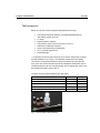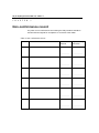
1
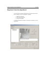
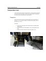
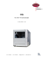
Antec Industrieweg 12 2382 NV Zoeterwoude The Netherlands OQ For AS 110 autosampler 191.0022, Edition 1, 2013 T +31 71 5813333 | F +31 71 5813334 | [email protected] | www.myantec.com Copyright ©2013, Antec, The Netherlands. Contents of this publication may not be reproduced in any form or by any means (including electronic storage and retrieval or translation into a foreign language) without prior agreement and written consent from the copyright of the owner. The information contained in this document is subject to change without notice. ROXY, ALEXYS, DECADE, DECADE II, INTRO, Flexcell, SenCell, ISAAC, HyREF are trademarks of Antec. Whatman™ (word and device) and Whatrnan™ (word only) are trademarks of Whatman lnternational Ltd. SOLVENT IFD™ and AQUEOUS IFD™ are trademarks of Arbor Technologies, Inc. Clarity®, DataApex® are trademarks of DataApex Ltd. Microsoft® and Windows™ are trademarks of Microsoft Corporation. Excel is a registered trademark of the Microsoft Corporation. The software and the information provided herein is believed to be reliable. Antec shall not be liable for errors contained herein or for incidental or consequential damages in connection with the furnishing, performance, or use of software or this manual. All use of the software shall be entirely at the user’s own risk. Chapter 1 1 (of 24) Symbols Explanations of symbols & labels on the device or in user manual: Symbol Explanation The caution/warning sign denotes a hazard. It calls attention to a procedure or practice which, if not adhered to, could result in severe/lethal injury or damage/destruction of parts or all of the equipment. Do not proceed beyond a warning sign until the indicated conditions are fully understood and met. The attention sign signals relevant information. Read this information, as it might be helpful. 2 (of 24) OQ procedure AS 110, edition 1 Safety practices The OQ procedure may only be performed by a qualified service engineer trained by the manufacturer. The following safety practices / protective measures are intended to ensure safe operation of the instrument. Electrical hazards Never open a device! Removal of protective panels on the instrument can result in exposure to potentially dangerous voltages which may lead to severe injury or loss of life! The instrument may only be opened by authorized service engineers of the manufacturer or a company authorized by the manufacturer. ! WARNING - RISK OF FIRE REPLACE FUSE AS MARKED WARNING - RISK OF ELECTRIC CHOCK ! Solvents Organic solvents are highly flammable. Since capillaries can detach from their screw fittings and allow solvent to escape, it is prohibited to have any open flames near the analytical system! If a leakage occurs, turn of the power of the instrument and remedy the situation immediately. Regularly check for leaks and clogged LC tubing and connections. Do not close or block drains or outlets. Do not allow flammable and/or toxic solvents to accumulate. Follow a regulated, approved waste disposal program. Never dispose of such products through the municipal sewage system. Toxicity: Organic solvents are toxic above a certain concentration. Ensure that work areas are always well-ventilated! Wear protective gloves, safety glasses and other relevant protective clothing when working on the device! Chapter 1 3 (of 24) Table of contents Symbols 1 Safety practices 2 Electrical hazards 2 Solvents 2 Table of contents 3 Introduction 5 Identification 7 Engineer 7 Reviewer/customer 7 Instruments 8 Test equipment 9 Communication test 11 Hardware verification 12 Alignment check & adjustment 13 Temperature test 15 Repeatability & Linearity test 18 What to do if the OQ failed 19 OQ certification 20 Non-conformance record 22 4 (of 24) OQ procedure AS 110, edition 1 Chapter 1 Introduction C H A P T E R 5 (of 24) 1 Introduction This document describes the Operational Qualification (OQ) process for the AS 110 auto sampler as advised by the manufacturer. It is the result from our interpretation of many regulations and laboratory practises. In addition, feedback from users and representatives helped us to finalize this procedure. A complete OQ for a AS 110 auto sampler consists of : 1. 2. 3. 4. 5. Communication test Hardware verification Alignment check & adjustment Temperature test (for auto samplers with cooling option). Repeatability & linearity test* *) The repeatability & linearity test is based on the HPLC performance test which is part of the PQ for HPLC-ECD systems, p/n 180.0028. So to execute test 5 all part (column, MOPEG test sample, concentrated buffer) of the PQ for HPLC/ECD kit p/n 250.3040 are required. This document guides you, a trained and qualified person, through the operational qualification of the AS 110 auto sampler. The owner's management approves the successful completion of this qualification by signing off the OQ certification at the end of this document. All qualification checks in this document must be approved, or must be marked "n/a" if not applicable. Any deviation observed must be documented in the 'non-conformance' record. All relevant documents regarding this operational qualification must be filed together in one location. As regulations and customer requirements may change, manufacturer reserves the right to introduce changes without prior notice. For details on functionality, operation and theory references are made to the instrument user manual. 6 (of 24) OQ procedure AS 110, edition 1 Chapter 2 Identification C H A P T E R 7 (of 24) 2 Identification Engineer The undersigned engineer certifies to be trained and qualified to perform an OQ on an AS 110 auto sampler. Company: Performer: Name Initials Title: Signature: Reviewer/customer The undersigned reviewer/customer accepts that the above-mentioned engineer is trained and qualified to perform an OQ on an AS 110 auto sampler. Company: Reviewer/Customer: Name Initials Title: Signature: (Owner-designated authorized person) 8 (of 24) OQ procedure AS 110, edition 1 Instruments AS 110 p/n: s/n: AS 110 micro p/n: s/n: Cooling option 10-port valve* AS software version ASM version Manufacturer Antec Supplier Date of delivery Warranty until * In case a 10-port valve is installed with a dual loop configuration in the auto sampler flow path please reconfigure the flow path to a single loop configuration to be able to perform the reproducibility test. See document p/n 181.7032 (10 port-to 6 port valve changer kit). Verified by (customer): ………………………….. Comments: Deviations (Y/N): …… Chapter 2 Identification 9 (of 24) Test equipment Below an overview of the required tools/equipment are listed: Antec Electrochemical detector (Intro/DECADE/DECADE II) with Glassy Carbon flow cell LC pump Data acquisition software Temperature sensor with an accuracy of ±0.5 °C Alias Service Manager software PQ for HPLC/ECD kit (p/n 250.3040)* AS 110 needle stripper tool Small flash light *) To perform the HPLC tests of the PQ, a kit can be ordered that contains the test substance, the column, concentrated mobile phase and tubing connections for the part between the injector and flow cell (see table below). After use, the test substance and concentrated mobile phase can be reordered with the info from the table below, but the tubing and column can be reused when taken proper care of. Contents of ‘PQ for HPLC/ECD kit’ (p/n 250.3040) Description Part no HPLC column for PQ 250.1050 1 MOPEG 2 µmole/L, 2 mL for PQ 250.1062 3 Concentrated buffer for PQ 250.1064 1 AS100/AS110 outlet assembly, 130 µm 180.0230 1 DECADE II inlet assembly, 130 µm 180.0232 1 Fig. 1. Part of PQ for HPLC/ECD kit. Qty 10 (of 24) OQ procedure AS 110, edition 1 The following documents should be available on site (can be downloaded from the Antec web site www.myantec.com) for the OQ: 180.0028 180.0028C 193.0020 PQ for HPLC-ECD systems PQ appendices AS 110 service manual Instruments & Test materials Pump Type Serial number Acquisition software Type Serial number Revision Detector Type Serial number Calibration date Flow cell Type WE/diameter REF electrode Serial number Temperature sensor Type Serial number Calibration date Column for PQ Type Serial number 2 µM MOPEG solution Lot number Expiration date Mobile phase for PQ Lot number Expiration date Verified by (customer): ………………………….. Comments: Deviations (Y/N): …… Chapter 3 Communication test C H A P T E R 11 (of 24) 3 Communication test Execute the following steps to check the communication and verify the instrument configuration: Connect the serial communication cable. Start ASM software. Select Communication and select the correct com port of the PC Select Alias™ Direct control. Initialize the instrument and check if the Status of the instrument will be displayed ‘ Idle’. Check Software version, System boot ID and Serial number stalled options are matching with the selectable options in the direct control window. Write down the AS software version on page 6 (instruments). Successful performance: instruments display all requested versions and initialize without any error message. In case of failure see the AS 110 service manual for directions to remedy the problem. Result: Passed Failed Verified by (customer): ………………………….. Comments: Deviations (Y/N): …… 12 (of 24) OQ procedure AS 110, edition 1 Hardware verification Open ASM direct control and check the following hardware modules of the AS 110 Auto sampler Select in the section Tray, the button Front and, check if the Tray moves to the front position. Select in the section Valve, the button Load and check if the valve is switching from the Inject position to the Load position. Return the valve to the Inject position and check if the flow path is switched as the diagram is displaying. Install the wash bottle, preferable with 80% H2O and 20%IPA Select in the section Initial wash, the Start button, check if the complete flow path will be filled with wash solvent and no air bubbles are remained in the flow path. Check the AS flow path for visual leakage. Successful performance: no positioning errors and no air bubbles or leakage visible in the flow path. In case of failure see the AS 110 service manual for directions to remedy the problem. Result: Passed Failed Verified by (customer): ………………………….. Comments: Deviations (Y/N): …… Chapter 3 Alignment check & adjustment 13 (of 24) Alignment check & adjustment In this procedure the following adjustments are checked using the ALIAS service manager and can be re-adjusted if required : Needle-tray adjustment Wash position adjustment Syringe home position For detailed instructions see chapter 7 of document 191.0020 AS 110 service manual. 14 (of 24) OQ procedure AS 110, edition 1 Execute the following steps: Open ASM service menu and go to the service menu. Select the option ‘main adjustments. Start the Tray-needle alignment wizard and follow the instructions on the PC screen. Use a flash light to locate and illuminate the alignment notches in the black tray table as they are very small. Continue with the Wash position alignment and follow the instructions on the PC screen. Continue with the syringe home position alignment and follow the instructions on the PC screen. Successful performance: if all alignment procedures are completed successfully. In case of failure see the AS 110 service manual for directions to remedy the problem. Result: Passed Failed Verified by (customer): ………………………….. Comments: Deviations (Y/N): …… Chapter 3 Temperature test 15 (of 24) Temperature test In the case the auto sampler is equipped with a cooling option the temperature test should be executed to check if the cooling system is operating in accordance with the manufacturer's specifications. Preparation The environmental conditions should preferably meet a temperature of maximum 24 °C and 80% humidity. The thermometer should have an accuracy of +/- 0.5 °C. Procedure Place the tip of the probe of the thermometer in a vial filled with distilled water. Place the vial in the 48-vial adapter in one of the positions in the front. Close the sample compartment with the isolation cover. 16 (of 24) OQ procedure AS 110, edition 1 Set the temperature in ASM direct control to a set point of 4°C and switch the cooling on. If the environmental temperature is 24°C or higher, execute the T test at a SET temperature that is 20°C below the room temperature (room temperate 26°C ->set point 6°C etc.). Let the cooler stabilize a while (f.e. 15 min) and measure the temperature, repeat if necessary. Stabilization will take a while but should not take longer than 1 hour. Record the actual temperature of the temperature probe. The specification of the temperature accuracy of the temperature within the sample compartment is: set point ± 2°C. So in case of a successful temperature test the actual temperature after stabilization should be within 4 ± 2°C. Result: Passed Failed Chapter 3 Temperature test Verified by (customer): ………………………….. Comments: 17 (of 24) Deviations (Y/N): …… 18 (of 24) OQ procedure AS 110, edition 1 Repeatability & Linearity test To execute this test the following documentation is required: (1) p/n 180.0028 PQ for HPLC-ECD systems (2) p/n 180.0028C PQ appendices Furthermore, the parts (column, MOPEG test sample, concentrated buffer and tubing) of the PQ for HPLC-ECD kit p/n 250.3040 are required to perform the test. Execute the test procedure as described in chapter 4 ‘HPLC performance test’ in document p/n 180.0028 PQ for HPLC-ECD systems. Write the relevant test results down in the table and indicate passed or failed in the last column. Results Specified* Measured Result* HPLC TESTS Column test Plate number Retention time > 1500 < 5 min ……. ……. min …………. …………. ……. nA …………. ……. ……. % % …………. …………. Signal Height > …...... nA Repeatability %RSD t %RSD area < 0.5 % < 3.0 % Linearity Correlation coefficient r > 0.997 ……. …………. *Specifications for some of the HPLC tests are hardware dependent; check the applicable specs on page 18 of document p/n 180.0028 PQ for HPLC-ECD systems. Verified by (customer): ………………………….. Comments: Deviations (Y/N): …… Chapter 3 Repeatability & Linearity test 19 (of 24) What to do if the OQ failed Steps to take when the AS 110 auto sampler fails the OQ test: 1. Finish the OQ as far as possible. If one section is failed, it may very well be that also other tests will fail that will help in finding the problem. In case tests are failed fill in a non-conformance report for every failed test. 2. Find the corresponding sections in the service documentation and see what test, recommendations and fixes are given to solve the problem. 3. If not successful in fixing the problem contact Antec for service or further instructions. 20 (of 24) OQ procedure AS 110, edition 1 C H A P T E R 4 OQ certification The Operational Qualification has been carried out in accordance to the OQ procedure and has been carried out to the satisfaction of both parties. All tests as described in this document have been successfully completed, and all results are within specifications. Executing engineer (Antec representative) Technician name & signature …………………………... ……………………..…. Company Date Customer (authorised to sign) Name & signature Company/dept. Date …………………………... ……………………..…. Chapter 4 OQ certification Comments 21 (of 24) 22 (of 24) OQ procedure AS 110, edition 1 C H A P T E R 5 Non-conformance record Any case of non-conformance found during the OQ procedure should be documented and signed for acceptance or corrective action taken. Table 2. Non conformance record. Ref. Non-conformance and action taken Signature customer Sign. executing technician ……………… ……………… ……………… ……………… ……………… ……………… ……………… ……………… ……………… ……………… ……………… ……………… 1 2 3 4 5 6