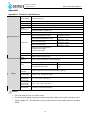
1
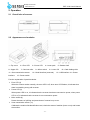
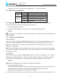
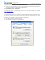
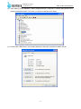
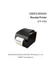
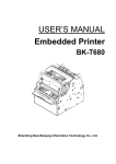
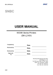
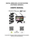
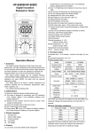
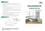
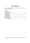
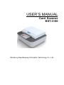
USER’S MANUAL
Card Scanner
BST-3100
Shandong New Beiyang Information Technology Co., Ltd.
v
www.sensis.ru
BST-3100 User’s Manual
General Safety Information
Before using the scanner, please read the following items carefully.
1.
Safety warning
Warning: Please operate the scanner according to the warning in this manual to avoid malfunction
of device due to incorrect operation.
2.
Caution
1)
Install the scanner on a flat and stable place.
2)
Reserve adequate space around the scanner so that convenient operation and maintenance can
be performed.
3)
Keep the scanner away from water source, and avoid direct exposure to sunlight, strong light and
heat of fire.
4)
Don’t use or store the scanner in a place exposed to high temperature, moisture and serious
pollution.
5)
Do not place the scanner on a place exposed to vibration or impact.
6)
No dew condensation is allowed to the scanner. In case of such condensation, do not turn on the
power until it has completely evaporated.
7)
Connect the power adapter of scanner to a proper grounding socket and avoid using the same
socket with large motors or other devices that can lead to the vibration of power voltage.
8)
Disconnect the power when the scanner is not used for a long time.
9)
Do not let the water or electric material (like metal) go into the scanner. If this happens, turn off the
power immediately.
10) The user cannot disassemble the scanner himself.
11) Keep this manual safe and at hand for ready reference.
-2-
www.sensis.ru
BST-3100 User’s Manual
Contents
1
Overview . .......................................................................................................................................- 1
1.1
Brief introduction . .......................................................................................................................- 1 -
1.2
Unpacking . .................................................................................................................................- 1 -
1.3
Position for installing scanner.....................................................................................................- 1 -
1.4
Connecting power adapter .........................................................................................................- 2 -
1.5
Connecting communication cable ..............................................................................................- 2 -
2
Operation . ....................................................................................................................................- 3 -
2.1
Overall size of scanner...............................................................................................................- 3 -
2.2
Appearance and modules . .........................................................................................................- 3 -
2.3
LED function explanation ...........................................................................................................- 4 -
2.4
Start scanner . .............................................................................................................................- 4 -
2.4.1
Start up and self-test ..............................................................................................................- 4 -
2.4.2
Sensor and CIS calibration . ..................................................................................................- 4 -
2.5
Installation and use of software..................................................................................................- 5 -
2.5.1
Installing driver.......................................................................................................................- 5 -
2.5.2
Use of tool software ...............................................................................................................- 9 -
3
Interface signal . ..........................................................................................................................- 10 -
3.1
USB interface . ..........................................................................................................................- 10 -
3.2
Power interface definition ......................................................................................................... - 11 -
3.3
Serial interface definition .......................................................................................................... - 11 -
4
Routine maintenance .................................................................................................................- 12 -
4.1
CIS glass cleaning . ..................................................................................................................- 12 -
4.2
Sensor cleaning . ......................................................................................................................- 12 -
4.3
Platen roller cleaning. ...............................................................................................................- 12 -
5
Troubleshooting. .........................................................................................................................- 13 -
5.1
LED status indication . ..............................................................................................................- 13 -
Appendix . ..........................................................................................................................................- 14 Appendix 1 Technical specifications . ................................................................................................- 14
-3-
BST-3100 User’s Manual
www.sensis.ru
1 Overview
1.1 Brief introduction
BST-3100 card scanner not only can be used as whole machine, but also can be used as embedded
scan mechanism. Its maximum scanning width is 68mm, and it is mainly used in communication,
finance, education, insurance, etc.
BST-3100 scanner can be connected to the computer via USB interface, and drivers are available for
WINDOWS2000/XP/2003/Vista/2008/Win7 operating systems and the software development kit
based on DLL.
BST-3100 scanner is configured with the following function:
¾
Support one-side and two-side scan (second-generation ID card);
¾
Support image automatic cutting;
¾
Support CIS correction using command;
¾
Support checking the scan sensor using command;
¾
Support updating firmware online;
¾
Support the scanning and uploading of multicolor and grayscale images under online condition;
¾
Support identification of second-generation ID card (optional);
¾
Support the electronic information uploading of second-generation ID card under online condition
(optional);
¾
Support card retraction (front in and front out, front in and back out);
¾
OCR function.
1.2 Unpacking
Unpack the package of scanner and check whether all items, which are listed on the packing list, are
present and in a good condition. If any item is damaged or missing, please contact your dealer.
1.3 Position for installing scanner
It is placed flat on the surface, and needs to be waterproof, dampproof and dustproof. The gradient
should be no more than 15° while installing the scanner.
-1-
www.sensis.ru
BST-3100 User’s Manual
1.4 Connecting power adapter
(1) Make sure that the power of scanner is turned off;
(2) Insert the other end of power adapter into interface of power adapter behind scanner;
(3) Insert the other end of AC power cable into 220V power socket;
Caution:
Please disconnect the power of scanner when the scanner idles for a long time.
1.5 Connecting communication cable
(1) Make sure that the power of scanner is turned off;
(2) Insert the communication cable into corresponding interface;
(3) Insert the other end of communication cable into the main frame of scanner.
Caution:
Please be careful not to connect or disconnect the USB communication cable when the power of
scanner is turned on.
-2-
www.sensis.ru
BST-3100 User’s Manual
2 Operation
2.1 Overall size of scanner
2.2 Appearance and modules
1—Top cover
2—Error LED
6—Upper CIS
7—Card out roller
11—Scan transmissive sensor
interface
3—Power LED
4—Lower path
8—Micro switch
5—Bottom shell
9—Lower CIS
12—Serial interface (reserved)
10—Card feeding roller
13—USB interface 14—Power
15—Power switch
Function explanation of partial modules:
¾
Error LED (2)
When the scanner works normally, the error LED is off; when error LED flashes, it indicates that
there is something wrong with scanner.
¾
Power LED (3)
When power LED is on, it indicates that the scanner has been connected to power; when power
LED is off, it indicates that the scanner is not connected to power.
¾
Micro switch (8)
Detect the status of uplifting and press-down of scanner’s top cover.
¾
Scan transmissive sensor (11)
Calibrate the medium like identification card, check the status of medium (have or not) and locate
the medium.
-3-
www.sensis.ru
¾
BST-3100 User’s Manual
Power switch (15)
Press down “O” to turn off the power and press down “-” to turn on the power.
2.3 LED function explanation
LED
Power LED
(green)
Status
Always on
Always off
Always off
Error LED
(red)
Always on
Flash
2.4 Start scanner 2.4.1
Explanation
The scanner is powered on.
The scanner is powered off.
The scanner is in standby mode.
The scanner
reads and identifies
second-generation ID card (optional).
Scanner error, such as card jam or top
cover uplifting.
Start up and self-test (1) Make sure that power adapter and
communication cable have been connected correctly, and turn
on the power switch of scanner;
(2) The scanner tests itself and only power LED is on after finishing the self-test.
Caution:
If the scanner can’t be started or it can’t work normally after starting it, please contact with local
agency or SNBC.
2.4.2
Sensor and CIS calibration
Sensor calibration:
Open the port with tool software IDDigitalCopierTool.exe, then click “Sensor Calibration” and put
a piece of A4 paper whose width is the same with the path and whose length is 20cm for calibration. If the paper comes out from the path and error LED doesn’t alarm error, then the
calibration is successful.
Note: When putting paper into the card entry, there may occur that the scanner doesn’t feed paper.
At that moment, please wait patiently and not take off the paper, and the scanner will feed paper
automatically after 10s.
CIS calibration:
Open the port with tool software IDDigitalCopierTool.exe, and click “CIS Calibration”. Put a piece of
coated paper whose thickness is 0.8mm and whose length is 20cm for calibration according
to prompts. After the calibration is over, there will be the prompt of calibrating CIS successfully.
Caution:
¾
When the following case occurs, the sensor needs to be calibrated:
The scanner doesn’t feed card.
Open upper software and start scanning. If the scanner doesn’t feed card when the card is put on
the sensor, then it is required to close the upper software and calibrate the sensor;
¾
When the following case occurs, CIS needs to be calibrated:
(1) When there are abnormal lines or color cast in the image, check whether the surface of CIS
-4-
BST-3100 User’s Manual
www.sensis.ru
glass is clean. If it is clean, then it is required to calibrate CIS.
(2) If there is no card in the path when turning on the scanner but the scanner alarms card jam, then
it is required to calibrate CIS firstly and then calibrate sensor.
2.5 Installation and use of software
The CD of this scanner is configured with driver, and you can also download it from website
www.newbeiyang.com.cn .
2.5.1
Installing driver
The 32-bit systems that the driver supports are Windows 2000/Windows XP/ WindowsVista/ Win7,
and the 64-bit systems that the driver supports are Windows XP/ WindowsVista/ Win7. Take
Windows XP as an example to explain the process of installing driver:
(1) Click “My Computer”, and then select property;
(2) Click “Hardware” and then select “Device Manager”;
-5-
www.sensis.ru
BST-3100 User’s Manual
(3) After clicking “Device Manager”, select “Imaging devices”. If there is a ‘!’ before USB-Device or the
device is identified as BST-3100, then you need to install the driver again;
(4) Double click “USB Device”, the property dialog box will come out and then select “Driver”;
-6-
BST-3100 User’s Manual
www.sensis.ru
(5) Click “Update Driver”, then it will come out “Hardware Update Wizard” and select “No, not this
time”.
(6) Click “Next”. Select “Install from a list or specific location (Advanced)”;
-7-
www.sensis.ru
BST-3100 User’s Manual
(7) Click “Next”. Click “Browse” to select the route of “Driver”, and then click “Next” and install the
driver according to prompts.
-8-
www.sensis.ru
2.5.2
BST-3100 User’s Manual
Use of tool software
For BST-3100 scanner, we provide following tool: demo program. Following is the brief introduction
and explanation of tool software.
¾
Demo program
Its software is IDDigitalCopierDemo, which can provide demo program of four languages (VC, VB,
Delphi and C#). It is mainly used for demonstrating the typical function of identification card scanner,
which provides reference for user to program. The systems it supports are WINDOWS
2000/XP/Vista/Win 7, and following is the main interface of IDDigitalCopierDemo_VC: (Detailed
usage please refer to the help file in the tool software package)
-9-
www.sensis.ru
BST-3100 User’s Manual
3 Interface signal
3.1 USB interface
The USB interface of scanner works under full speed mode and supports USB2.0 protocol.
The connector adopts USB type-B socket and supports USB HUB.
USB interface cable complies with USB specifications, with the scanner end adopting type-A plug and
the user end adopting type-B plug, the length of which is 1.5m.
Interface signal is defined as below:
Pin
Signal name
1
VBUS(+5V)
2
D-
3
D+
4
GND
Frame
Shielded
- 10 -
www.sensis.ru
BST-3100 User’s Manual
3.2 Power interface definition
Power interface is used for the connection of scanner and power adapter, the pins of which are defined
as follows:
Pin
Signal name
1
GND
2
GND
3
+24V
Interface model is as below:
NO
Name
Model
1
Scanner end (socket)
DC-005 Φ2.0 or similar product
2
Power adapter end (plug)
DP-005 Φ2.0 or similar product
3.3 Serial interface definition
The serial interface of scanner is compatible with RS-232 standard, and its interface socket is a
9-hole socket.
PIN No.
PIN2
Signal definition
RXD
PIN 3
PIN 4 7
TXD
RST
PIN 5
GND
PIN6 8
CTS
PIN 1 9
Not connected
- 11 -
www.sensis.ru
BST-3100 User’s Manual
4 Routine maintenance
Clean CIS, platen roller and sensor routinely according to the following steps. If the scanner is used in
harsh environment, the times of routine maintenance can be increased properly.
4.1 CIS glass cleaning
When any of the following cases occurs, CIS glass surface should be cleaned:
¾
The scan image is not clear;
¾
The scan image has abnormal lines.
CIS glass cleaning steps are as follows:
(1) Power off the scanner and open its top cover;
(2) Wipe CIS glass surface with alcohol cotton ball (it should be wrung out);
(3) Wait for 5-10 minutes until the alcohol evaporates completely and close the top cover.
Note: The CIS glass surface inside the scanner can be very hot when the scanner is being used.
Thus, power off the scanner and wait for 10 minutes before the cleaning.
4.2 Sensor cleaning
When any of the following cases occurs, clean the sensor:
¾
During the scanning, the scanner reports card jam error once in a
while; ¾
The scanner reports card jam error at power-up initialization.
The steps to clean the sensor are as below:
(1) Power off the scanner and open its top cover;
(2) Wipe off the dust and stains on the surface of the transmissive sensor with alcohol cotton ball (it
should be wrung out);
(3) Wait for 5-10 minutes until the alcohol evaporates completely and close the top cover.
4.3 Platen roller cleaning
When any of the following cases occurs, the platen roller should be cleaned:
¾
Card jam occurs during scanning;
¾
Feed or retract the card with big noise;
¾
Foreign matter sticks onto the platen roller.
The steps to clean the platen roller are as follows:
(1) Power off the scanner and open its top cover;
(2) Wipe off the dust and stains on the surface of the platen roller with alcohol cotton ball (it should
be wrung out) while turning the platen roller;
(3) Wait for 5-10 minutes until the alcohol evaporates completely and close the top cover.
Caution:
¾
Before starting the routine maintenance of the scanner, make sure that it is power-off;
¾
Avoid touching CIS surface with hand or metal objects and do not scratch CIS glass surface,
platen roller and sensor surface with tools like forceps;
¾
Do not use organic solvent like gasoline, acetone, etc. to wipe CIS glass surface and platen
roller;
¾
Do not power on the scanner before the alcohol evaporates completely.
- 12 -
www.sensis.ru
BST-3100 User’s Manual
5 Troubleshooting
When a malfunction occurs, refer to this chapter for solution. If you cannot find a solution in this
chapter, please contact your local dealer or manufacturer for assistance.
5.1 LED status indication
When a malfunction or abnormal condition occurs, the error LED flashes. Then the scanner stops
scanning and the scanner and the host will disconnect. Please check the times of continuous flashing,
and then refer to the following methods for solution.
Error information
LED
Recovery
Calibration error (CIS
or sensor)
Clear the error by lifting up the top cover
Lift up the top cover, take the card away and
close the top cover to clear the error.
Card jam
Close the top cover.
Top cover lift-up
Recover the voltage to normal range
Abnormal voltage
- 13 -
www.sensis.ru
BST-3100 User’s Manual
Appendix
Appendix 1 Technical specifications
Scan method
Two-side scanning
Scan element
CIS (width 84mm)
Light source
RGB (LED three-color light source)
Scan resolution
Other
performance
Scan speed
Scan performance
Scan area
300*300dpi (optical resolution)
256 gray levels
The scan image has the function of auto adjustment, and it can be cut into the size
consistent with the original card.
Multicolor: 80mm/s (MAX), grayscale: 130mm/s (MAX)
Length × width: 95mm × 65mm
Size of first-generation ID card
Thickness: 0.55mm
Length × width: 85mm × 55mm
Size of second-generation ID card
Thickness: 1.1mm
Length × width: 95mm × 67mm
Size of driver's license
Thickness: 0.6mm
Length × width: 95mm × 67mm
Size of business card
Thickness: 0.3mm
Max. scan area: (vertical scan)
Horizontal area: 68mm
Vertical area: 150mm
Scan media
Thickness: 0.3 ~ 1.1mm
Processing
width
68mm×150mm (vertical scan)
Sensor
Scan: card in/out detection; top cover detection
LED
Others
Power (green)
Always on after power-up
Status (red): indicating different status
through flashing frequency
Main status: card jam, top cover lift-up,
etc.
Communication
interface
USB 2.0 high speed interface, serial interface (optional)
Power supply
24V±5% DC, 1A (external power)
Operating
temperature
and humidity
Storage
temperature
and humidity
Overall size
5℃~45℃, 20%~90% (40℃)
-20℃~60℃, 20%~90% (40℃)
147mm(L)×123mm(W)×67(H)mm
Caution:
¾
DPI: scan dots per inch (1 inch≈25.4 mm);
¾
The actual scan speed is relevant to data transmission speed, the control command, power
supply voltage, etc., and therefore it may be lower than the scan speed shown in the table
above.
- 14 -