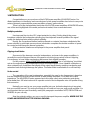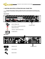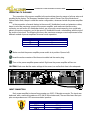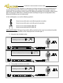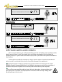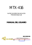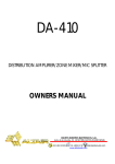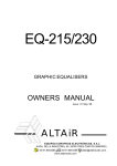
1
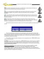
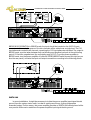
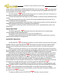
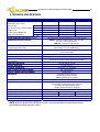
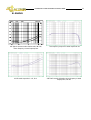
A3.5,7,11
PROFESSIONAL POWER AMPLIFIERS
ADVANTAGE SERIES
NOTICE: PIN 2+
OWNERS MANUAL
EQUIPOS EUROPEOS ELECTRÓNICOS, S.A.L
Avda. de la Industria, 50. 28760 TRES CANTOS-MADRID (SPAIN).
34-1-804 32 65
34-1-804 43 58
[email protected]
www.altairaudio.com
2
PROFESSIONAL POWER AMPLIFIERS ADVANTAGE SERIES
CONTENTS
1. INTRODUCTION
2. SWITCHES, INDICATORS, ATTENUATORS AND CONNECTORS
FRONT PANEL
REAR PANEL
3. WORKING PRECAUTIONS
4. INSTALLATION
UNPACKING
MOUNTING
CHANGING THE FUSE
CONNECTING TO THE MAINS
INPUT CONNECTION
UNBALANCED INPUT
BALANCED INPUT
OUTPUT POWER CONNECTION. MODES OF OPERATION
STEREO MODE OPERATION
BRIDGE MODE OPERATION
EARTH LINK
5. OPERATION
POWER UP
INPUT ATTENUATORS
CLIP INDICATORS (INPUT SIGNAL OVERLOAD)
SIGNAL INDICATORS
ON/PROTECT INDICATORS
FAN
LOAD IMPEDANCES
MAINTENANCE
AMPLIFIER CONDITIONS
6. SPECIAL OPERATIONS
INPUT SENSITIVITY/GAIN ADJUST
LIMITER ON/OFF
CHANGING THE MAINS VOLTAGE
7. DISTRIBUTED SYSTEMS APPLICATION (PUBLIC ADDRESS)
8. OPTIONAL CROSS-OVER CARD
9. TECHNICAL SPECIFICATIONS
10. GRAPHS
11. WARRANTY
3
4
4
4
5
5
5
6
6
7
7
8
9
9
10
11
11
12
12
12
12
13
13
14
14
14
14
15
17
17
18
19
19
20
21
22
PROFESSIONAL POWER AMPLIFIERS ADVANTAGE SERIES
3
1. INTRODUCTION
Congratulations on your purchase of the ALTAIR power amplifier ADVANTAGE series. Our
dilated experience in the design and manufacture of audio power amplifiers has led us to carry out a
series of general purpose bipolar power amplifiers of great performances.
There is a lot the characteristics that make of the ALTAIR power amplifiers ADVANTAGES series,
one of the most highlighted of the audio professional market, here enumerated some:
Multiple protection
Has improved the circuits of DC output protection by relay. Guiding directly the power
transistors output to the loudspeakers binding post has improved several qualities of the signal
quality, the damping factor and the global reliability.
Equally, the conventional thermal switches (based on contacts) has been substituted of the
power modules by solid state sensors whose information completes the double condition of speed
fan control and discharge the thermal protection.
All the protection situations are displayed in the power amplifier front panel.
Clipping circuit limiter
Since most of the damage caused to loudspeakers, and even to the power amplifiers, is
normally the result of the permanence of the power unit during long periods of time in clipping,
it is necessary to have limiter mechanisms that assure their reliable operation.
For this purpose, all the ADVANTAGE series power amplifiers has a "soft-clipping" circuit that
acts on the output power by comparing the input and output signals. Once it detects a distortion or
other noticeable cut, it stabilises the integrity of the output signal thereby avoiding overloading and
saturation levels that might damage the system. This limiter effect is switchable on or off internally.
Under control
The conception of the new loudspeakers, especially the uses for low frequencies is based on
that the amplifiers that govern them behave as ideal voltage amplifiers, is say with zero output
impedance. The ADVANTAGE series approaches to this value nearly zero presenting a damping
factor better than 300 what redounds in a perfect control of the loudspeaker voice coil position along
their excursion.
Naturally, you want to use your power amplifier just now, but before beginning is important
that you read this manual. This manual will help you to install and use your new power amplifier. It is
very important that you read it carefully, mainly the paragraphs marked as NOTE, PRECAUTION and
DANGER, for your security.
Save the original packing, you can re-use it to transport the power amplifier. NEVER SHIP THE
POWER AMPLIFIER WITHOUT THE ORIGINAL PACKING.
PROFESSIONAL POWER AMPLIFIERS ADVANTAGE SERIES
2. SWITCHES, INDICATORS, ATTENUATORS AND CONNECTORS.
These are the switches, indicators, attenuators and connectors that you could find in your
power amplifier. The description and explanation of each one, you will find it in the corresponding
section.
FRONT PANEL:
CH-1
-15 dB
-9
-3
-30
CLIP
A 11
CH-2
-15 dB
-20
-20
-9
-30
-3
SIGNAL ON/PROT
CLIP
-oo
0
-oo
SIGNAL ON/PROT
0
1
0
INPUT ATTENUATOR.
COOLING VENTS
INPUT SIGNAL OVERLOAD INDICATOR.
CLIP
SIGNAL
SIGNAL INDICATOR.
ON/PROT
TURN ON / PROTECT INDICATOR.
1
0
POWER SWITCH.
REAR PANEL:
BINDING POST.
FUSE HOLDER.
MAINS CORD.
COOLING VENTS
4
PROFESSIONAL POWER AMPLIFIERS ADVANTAGE SERIES
5
EARTH LINK SWITCH.
INPUT SIGNAL CONNECTOR XLR-3-31.
STEREO/ BRIDGE SWITCH.
XLR-3-32 OUTPUT SIGNAL CONNECTOR.
(ONLY WITH THE OPTIONAL CROSSOVER CARD FITTED).
INPUT SIGNAL SELECTOR FOR EACH CHANNEL.
(ONLY WITH THE OPTIONAL CROSSOVER CARD FITTED).
3. WORKING PRECAUTIONS
The manufacturer cannot be held responsible for any damage that is incurred by not using the
power amplifier in compliance with the warranty or working precautions.
DANGER: High voltage inside the amplifier. ! Do not open !. The power amplifier doesn't
contain parts that can be repaired by the user. The power amplifier could have electric
power stored in their interior even disconnected it from the mains.
CAUTION: Protect the power amplifier from the rain and moisture. Ensure that no
objects or liquids enter it. If liquid is spilled into the power amplifier, disconnect the power
amplifier from the mains and consult a qualified service technician.
Don't place the power amplifier close to sources of heat. Also make sure that the front and the rear
panel there are free of obstructions, since the fan could not work properly and cause the thermal
protection work.
DANGER: The power amplifier output connectors could have high voltage. Make sure of turning off
the power amplifier before handling on these output connectors.
4. INSTALLATION
UNPACKING
Before leaving from factory, each power amplifier was carefully inspected and tested. Unpack
and inspect the power amplifier for any damage that may have occurred during shipment. If any
damage is found, doesn't connect the power amplifier to the mains, notify the salesperson
immediately, because the unit must be inspected by a qualified service technician.
PROFESSIONAL POWER AMPLIFIERS ADVANTAGE SERIES
6
Save the original packing, you could use if you need to transport the power amplifier. NEVER
SHIP THE POWER AMPLIFIER WITHOUT IT'S ORIGINAL PACKING.
MOUNTING
It is always advisable to mount the power amplifiers in rack, either for mobile or fixed
installations, for protection, safety, aesthetics, etc.
The ADVANTAGE series power amplifiers are designed for standard 19" rack mounting, and
occupy 2u high rack space.
Due to the weight of the unit, it should be securely fastened at the front and the back of the
cabinet. If the racks are carriage ones, it is advisable that have trays in order to allow the power
amplifier to rest on its base and in an elastic cradle, if possible. It is advisable, leave a separation
space between amplifiers and other units in order to facilitate its cooling, upon mounting the
amplifier in a rack.
In the mounting, either fixed or in rack, the cooling vents placed in the front and rear panel
should be free, so that the air circulates freely, and the amplifier could have a better heat
dissipation. In the same way, make sure that there are no heat sources near the front cooling vent,
because the fan exhaust cool air through this vent.
CHANGING THE FUSE
The power amplifiers are designed to work with slow blow type fuses of 6x32, whose values
in order to work with a mains voltage of 230V 50-60 Hz or 115V 50-60 Hz. are specified in the
following list:
MODEL
A3.5
A7
A11
FUSE (230V. 50-60 Hz)
T5A.
T6A.
T8A.
FUSE (115V. 50-60 Hz)
T8A.
T12A.
T16A.
Make sure that the power amplifier is disconnected from the mains.
At the power amplifier rear panel is placed the fuse holder. Unscrew the most external part of
the fuse holder.
Upon unscrewing the most external part of the fuse holder, the fuse will appear. Remove it
and change for a new one. Never use other type of element than a fuse.
Screw the external part of the fuse holder.
CAUTION: Always make sure upon changing the fuse, that this is the adequate.
PROFESSIONAL POWER AMPLIFIERS ADVANTAGE SERIES
7
CONNECTING TO THE MAINS
The connection of the power amplifier to the mains takes place by means of a three-wire cord
provided by the factory. The European standard colour code is: Brown-Live, Blue-Neutral and
Yellow/Green-Earth, keeps in mind this mains configuration, whenever handle the power amplifier
plug.
In the connection of several devices to the same AC distribution board and extension cables,
keeps in mind the maximum current of the power amplifier, and make sure that the mains
connector, as well as the AC distribution board, are of enough current capacity, since could take
place in the mains connector, and in the same AC distribution board a overheating, with the risk of
fire and/or short circuit. The following list shows the maximum average current requirement of the
different models of power amplifiers at normal music operation:
MODELS
A3.5
A7
A11
MAXIMUM CURRENT REQUIREMENT
2A.
4A.
6A.
Make sure that the power amplifier power switch is at position 0 (turned off).
Insert the male connector of the three-wire cable into the mains plug.
Turn on the power amplifier power switch. Right now the power amplifier will turn on.
CAUTION: Make sure that the mains voltage is the correct, as well as their fuse is the adequate.
INPUT CONNECTION
Each power amplifier's channel incorporates one XLR-3-31 female connector. The inputs are
balanced, with a nominal impedance of 20 KΩ (10 KΩ unbalanced). The next list shows the input
pins correspondence as A.E.S recommendation practice:
PIN 1
PIN 2
PIN 3
INPUT CONNECTOR XLR-3-31
GND
HOT (+)
COLD (-)
PROFESSIONAL POWER AMPLIFIERS ADVANTAGE SERIES
8
The input connection depends on two factors, the first is the type of input signal balanced or
unbalanced, and the second the ground configuration of the sound source (floating or groundreferenced). The next pictures shows some of the different possibilities of connection, relying on the
type of input signal, balanced or unbalanced and according to the ground configuration of the
equipment (floating or ground-referenced).
In the next diagrams, we use the following symbols:
Sound source with mains cord without ground connection.
Sound source with mains cord with ground connection.
Sound source with the EARTH-LINK OFF.
Sound source with the EARTH LINK ON.
UNBALANCED INPUT: This type of connection will be used when the sound source doesn't provide
balanced output. If it is possible, will be employed the connection type 1.
1) Using twin-lead shielded cable:
Floating sound source (
or
)
Ground-referenced sound source (
2)
or
Using single conductor coax cable:
Floating sound source (
or
)
)
PROFESSIONAL POWER AMPLIFIERS ADVANTAGE SERIES
Ground-referenced sound source (
or
)
or
)
9
BALANCED INPUT:
Floating sound source (
or
Ground-referenced sound source (
)
OUTPUT POWER CONNECTION. MODES OF OPERATION
Each channel includes a pair of five-way binding post. The red binding post is positive and the
black is ground. Keep in mind the polarity upon connecting the speakers since changing the
speaker polarity of a system reduces the total output power by the effect of the phase cancellations
mechanisms.
In the output connection it is necessary to keep in mind a series of important precautions in
order to avoid an accidental short circuit or a possible damage in the equipment:
Consider the power-handling capacity of your speakers before connecting it to the power
amplifier. Equipos Europeos Electrónicos is not liable for damage occurred by the connection of
speakers to the power amplifier with a nominal power lower that the power amplifier.
Turn off the power amplifier and turn down the input attenuators, whenever takes place
an output power connection. The output power connectors could have high voltage, with
the rising danger of short circuit.
PROFESSIONAL POWER AMPLIFIERS ADVANTAGE SERIES
10
Never put the output power connectors in parallel. This connection doesn't increase the
power and could cause the break of the power amplifier.
Do not connect the power amplifier output connectors to the output connectors of any
other power amplifier. This connection could cause the break of one or both power
amplifiers.
Do not connect the output connector ground (black binding post) to any input connector
ground (PIN 1 of the connector XLR-3-31). This could create a ground loop and could cause
feedback oscillations.
Use loudspeaker cables sizes capable to manage the output current of the power
amplifier. The selection of a good loudspeaker cable, with a good quality and an adequate
diameter is very important, and is one of the things that less is kept in mind.
The next list shows the maximum output current of the power amplifiers according to the
model:
MODELS
A3.5
A7
A11
MAXIMUM OUTPUT CURRENT
9A.
13A.
16,5A.
There are many factors that determine the loudspeaker cable diameter: the length of the
cable, the type of signal that is going to circulate for it, the output power of the power amplifier etc.
A cable with high resistance reduces the damping factor, limiting the power amplifier capacity for
controlling the speakers accurately.
The possible output connections, depends on the configuration of the STEREO/BRIDGE mode
switch on the rear panel:
CAUTION: Do not change the configuration of STEREO/BRIDGE switch unless the power amplifier is
first turned off. Before turn on the power amplifier, make sure that the mains, input and output
connections are correct. If doesn't follow these recommendations, could cause a power amplifier
and/or loudspeakers breakdown.
STEREO MODE OPERATION: In this mode the two channels of the power amplifier are totally
independent, so that the two input signals, and the two power outputs will be wiring
independently. In order to configure the power amplifier in STEREO mode, turn the amplifier off,
slide the STEREO/BRIDGE switch toward the left (as you face the rear panel), and wire the input and
output connections according to the next picture:
PROFESSIONAL POWER AMPLIFIERS ADVANTAGE SERIES
11
BRIDGE MODE OPERATION: In BRIDGE mode, the input should be inserted on the XLR CH! input
connector. In this mode the power of the two channels will be added over a single load. The CH1
input attenuator controls both channels, remaining the CH2 input attenuator disabled. The output in
BRIDGE mode, must be taken between both red binding post (positive load pole is the red binding
post of CH1 and the negative load, the red binding post of CH2). To put the power amplifier in
BRIDGE mode, turn the power amplifier off, slide the STEREO/BRIDGE switch toward the right (as you
face the rear panel), and wire the input and output connections according to the following picture:
EARTH LINK
In some installations, it might be necessary to isolate the power amplifier input signal electric
ground, from the system mains earth, in order to avoid ground loops, that could generate
unwanted noises. For this reason, the power amplifier provides an EARTH-LINK switch placed at the
rear panel to lift the mains earth from the power amplifier input signal electric ground.
12
PROFESSIONAL POWER AMPLIFIERS ADVANTAGE SERIES
MAINS EARTH LINKED WITH THE P. AMPLIFIER INPUT SIGNAL ELECTRIC GROUND.
MAINS EARTH LIFTED FROM THE P. AMPLIFIER INPUT SIGNAL ELECTRIC GROUND.
CAUTION: Sometimes, lifting the mains earth, by using a ground-lift connector,
cancels some hum noises on the audio system, but this is very dangerous and not
advisable, because should any circumstance part of the mains signal is derived to
the chassis, could cause a short circuit through our body, upon having eliminated
one of the working precautions of the unit. For this circumstance, NEVER lifts the
mains earth (use the EARTH-LINK switch of the unit) in order to avoid possible
accidents.
5. OPERATION
POWER UP
1
0
Plug in all input and output connectors (following the recommendations of the
sections INSTALLATION - INPUT CONNECTION AND INSTALLATION - OUTPUT
CONNECTION). Ensure that both power amplifier's input attenuators are turned fully
counter-clockwise ( -∞ position). At this time you can switch on the power amplifier.
Upon switch the power amplifier on, the delay turn on system takes place, that minimises the
effect of the transient currents on the loudspeakers. In a few seconds, the delay turn on system
stops working (a RELAY click will be listened) and the load is connected.
When turning on a rack of power amplifiers they should be switched on individually. The
practice of leaving all power amplifiers in a rack switched on and powering up the whole rack by
connecting it to the mains is dangerous and likely it blows the mains fuse of the rack power supply,
if with good approach, the rack has one. In a rack of power amplifiers, switch the power amplifiers
on in a one by one basis.
ON/PROT
Note that upon switching the power amplifier on, the ON/PROTECT indicator
lights red
(indicating that the power amplifier is cutting the output signal), and after a few seconds this led
changes to green and a RELAY click will be listened indicating that the power amplifier is connecting
the output signal to the loudspeakers. At this time you can turn up the power amplifier input
attenuators.
INPUT ATTENUATORS
Each power amplifier channel has an input signal attenuator, gauged. The
calibration is measured between ±1 dBu relative to the scale.
The input attenuators are independent for each channel in STEREO mode. In mode
BRIDGE both channels depend on the CH1 input attenuator.
CLIP INDICATORS (INPUT SIGNAL OVERLOAD)
CLIP
, illuminates when the power amplifier starts to saturate, moreover, if
The CLIP red LED
the limiter is ON, this LED indicates that the circuit limiter starts to work (for more information see
13
PROFESSIONAL POWER AMPLIFIERS ADVANTAGE SERIES
CLIP
section SPECIAL OPERATIONS- LIMITER CONFIGURATION). The CLIP indicators
are independent
in each channel, and indicate a real saturation, by comparing input and output continuously, and
are independent of the mains voltage.
CLIP
The CLIP indicators
also illuminates when there is an output short-circuit, whenever one
input signal is being introduced to the power amplifier.
To make the loudspeakers life longer, avoid this situation of overload during extended periods
of time.
If the input signal level is too high, don't turn the power amplifier limiter off, because it is an
efficient protection for the loudspeakers.
In general, the loudspeakers resist high peaks of instantaneous power, but when exposed to
extended saturations they lose any guarantee of good operation.
The saturation measuring circuit is sensitive to peaks; it has a quick attack time and a slow
release time.
SIGNAL INDICATORS
SIGNAL
The SIGNAL green LEDs
illuminates when the output signal of the corresponding
channel reaches 25 dBu before saturation.
These LEDs indicate signal presence in the power amplifier input.
This SIGNAL measurement circuit is sensitive to peaks; it has a quick attack time and a slow
release time to indicate the average power.
ON/PROTECT INDICATORS
ON/PROT
The ON/PROT LED
indicates the connection or disconnection of the load from the power
ON/PROT
amplifier. These bi-colour LED ON/PROT
illuminates in red when the load is disconnected
from the power amplifier and it illuminates in green when the load is connected to the power
amplifier.
Therefore, whenever this indicator is in red, will indicate us that the load is disconnected from
the power amplifier, and the power amplifier is not operative at that moment. This occurs when the
power amplifier is turned on, and when the ERROR or THERMAL protections are activated.
When the power amplifier output transistors reach 90ºC, the thermal protection circuit of the
corresponding channel is activated. The thermal protection, disconnects the load from the power
ON/PROT
amplifier, turning red the ON/PROT LED
of the corresponding channel. This only happens
under the most severe conditions of continuous overload; in such a case, it is essential to localise
and to rectify the cause of this overheating condition. The thermal protection circuit returns
automatically to its normal operation when the power amplifier output transistors drops under the
ON/PROT
security level, connecting the load again, and turning green the ON/PROT LED
.
The power amplifier load protection circuit, work when a continuous voltage appears in the
power amplifier output connectors, disconnecting the load from the power amplifier (the ON/PROT
ON/PROT
LED
of the corresponding channel illuminates on red). When the continuous voltage
disappear, the load protection circuit automatically, connects the load to the power amplifier, and
ON/PROT
the ON/PROT LED
turns green.
ON/PROT
The power amplifier has two ON/PROT LED
indicators, one per channel.
PROFESSIONAL POWER AMPLIFIERS ADVANTAGE SERIES
14
FAN
The power amplifier includes a thermally controlled system, which continuously regulates the
fan speed depending on, the heat energy it has to evacuate. This variable speed circuit avoids
abrupt changes of temperature and substantially extents the working life of the components builds
in. At power amplifier turn on, the fan rotates at maximum speed, in order to exhaust the maximum
dust possible. Soon after, the fan's speed drops to normal speed. The power amplifier fan rotates at
maximum speed also, in an overheating situation (when a thermal protection is activated) so that
the heat drops under the security level quickly.
The fan is placed inside the power amplifier, and incorporates some cooling vents in the front
and rear panel for which the air is evacuated, for that reason it is important make sure that the
cooling vents are always free so that the air could circulate with freedom.
LOAD IMPEDANCES
The power amplifiers ADVANTAGE series, are designed to drive a 4Ω or higher load
impedances in STEREO mode (8Ω or higher in Mode BRIDGE), without current limiting.
When the power amplifier is working in BRIDGE mode, the load impedance must be 8Ω or
higher, with the same consideration that in STEREO mode with 4Ω load impedance. This is because
in BRIDGE mode, each channel is like driving with the half load impedance.
MAINTENANCE
Periodically, and in a technical service, you must clean the dust and dirt accumulated inside
the power amplifier, especially in the heatsinks, the fan and the cooling vents, with a vacuum
cleaner or with an air-compressor gun. The dirt diminishes considerably the capacity of radiation
and ventilation.
The input attenuators (potentiometers) are sensitive to the dust accumulated, and therefore for
trouble free operation they must be cleaned with an air compressor gun or be changed if
necessary.
NOTE: Equipos Europeos Electrónicos don't recommend the use of spray cleaners because they
could damage the lubricant layer of the potentiometers. Use compressed air to clean them or
replace with similar parts.
AMPLIFIER CONDITIONS
INDICATORS
AMPLIFIER CONDITION
The power amplifier has just been turned on (it is still in
the initial delay) and it is not receiving an input signal. In
this case the ON/PROT indicators of both channels
would be illuminated in red.
OR
A protection was activated (ERROR or THERMAL). The
power amplifier is not receiving an input signal. In this
case would be illuminated in red the ON/PROT indicator
of the channel in which the protection has been
activated.
15
PROFESSIONAL POWER AMPLIFIERS ADVANTAGE SERIES
INDICATORS
AMPLIFIER CONDITION
The power amplifier has just been turned on (it is still in
the initial delay) and it is receiving an input signal. In this
case the ON/PROT indicators of both channels would be
illuminated in red.
OR
A protection was activated (ERROR or THERMAL). The
power amplifier is receiving an input signal. In this case
would be illuminated in red the ON/PROT indicator of the
channel in which the protection has been activated.
The channel with this indicator status is not receiving an
input signal, but is ready in order to receive it.
Normal operation. The channel with this indicator status is
receiving an input signal, and amplifying it.
The channel with this indicator status is receiving an input
signal too high. If the limiter is engaged, it will be working,
and if it is not engaged, the output signal will be
saturated.
The channel with this indicator status has its output in
short-circuit
There is no power to the amplifier, either because it is not
plugged or because the power switch is in the OFF
position.
INDICATORS
RED:
GREEN:
6. SPECIAL OPERATIONS
In order to configure some of the power amplifier possibilities it is necessary to open it,
removing the nine screws on the upper cover.
NOTE: This type of operations takes place with the unit open, for what it should be carried out by a
qualified technician.
DANGER: Before opening the amplifier, disconnect it from the mains. It is important to indicate that
although the unit is power out (with the power switch in 0 position), if it continues connected to the
mains there are different parts of the unit that are subjected to high voltage.
CAUTION: Protect the power amplifier from the rain and moisture, mainly if it is open. If liquid is
spilled into the power amplifier, disconnect it from the mains and consult a qualified service
technician.
The input sensitivity and limiter configuration of both channels, takes place in the driver card,
shown in the next figure (DRIVER A5/11 ALTAIR -081). This board is located parallel to the power
amplifier bottom plate. The driver board is wide, occupying almost the whole width of the power
amplifier. The input sensitivity configuration of both channels is close the XLR-3-31 of CH1, and the
limiter configuration is close the XLR-3-321 of CH2.
16
SENS._CH1
0 dBu.
S1
S2
SENS.
0 dBu. CH2
ON
OFF
J4
LIMITER
PROFESSIONAL POWER AMPLIFIERS ADVANTAGE SERIES
The voltage selector is placed in the left side of the power supply card, shown in the next
figure (POWER SUPPLY A5/11 ALTAIR -082). The power supply card is located in the front-left side of the
power amplifier, (as you face the front panel).
PROFESSIONAL POWER AMPLIFIERS ADVANTAGE SERIES
17
INPUT SENSITIVITY/GAIN ADJUST
The power amplifier input sensitivity may be configured with two resistors, one for each
channel. When not installed this resistors, the input SENSITIVITY (input level necessary in order to
produce the maximum output level) of the channel is 0 dBu, and with a resistor of 3K16 we obtain a
input SENSITIVITY of +8 dBu. These are the two extreme values of the resistor to configure the input
sensitivity. The factory configuration is with input sensitivity 0 dBu.
Channel 1
Channel 2
The different resistors to obtain input sensitivities between 0 dBu and +8 dBu are show in the
next table:
INPUT SENSITIVITY
0 dBu (0,77 V).
+1 dBu (0,87 V).
+2 dBu (0,98 V).
+3 dBu (1,10 V).
+4 dBu (1,23 V).
+5 dBu (1,38 V).
+6 dBu (1,55 V).
E+7 dBu (1,74 V).N(1/4W,
+8 dBu (1,95 V).
RESISTOR (1/4W, 1%)
Without resistor.
42K2.
20K0.
12K1.
9K09.
6K81.
5K23.
4K02.
3K16.
CAUTION: Never put a resistor to configure the input sensitivity less than 3K16. This can produce a
misoperate of the power amplifier.
The gain (times that the output signal is increased with respect to input signal), depends on the
power amplifier model, as well as of the input sensitivity configuration. In the next table is shown
the gains according to the power amplifier model and its input sensitivity configuration (with
intermediate input sensitivities, subtract the gain corresponding to 0 dBu with the configured input
sensitivity, and obtain the power amplifier gain i.e.: 36-6 = 30).
MODELS
A3.5
A7
A11
GAIN (dB)
INPUT SENSITIVITY
0 dBu (0,775 V).
+8 dBu (1,95 V).
31
23
34
26
36
28
LIMITER ON/OFF
The power amplifier's limiter reduces the input signal when the power amplifier starts to
saturate, which avoids high saturation and loudspeaker damage.
18
PROFESSIONAL POWER AMPLIFIERS ADVANTAGE SERIES
It is very advisable use the limiter circuit.
When the limiter ON/OFF switch is not pushed, the limiter is enable (ON). When this switch is
pushed, the limiter is disable (OFF).
The limiter configuration (ON/OFF) affects to both channels of the power amplifier.
The factory configuration is with the limiter enable (ON) in both channels.
LIMITER CONFIGURATION
Configuration
Switch position
ON
OFF
J4
CH1 -> LIMITER ON.
CH2 -> LIMITER ON.
LIMITER
ON
OFF
J4
CH1 -> LIMITER OFF.
CH2 -> LIMITER OFF.
LIMITER
CHANGING THE MAINS VOLTAGE
The power amplifier is set to operate at 230V, 50-60Hz or at 115V, 50-60Hz.
Make sure that the power amplifier is disconnected of the mains.
Set up the voltage selector, placed in the left side of the power supply card (POWER SUPPLY
A5/11 ALTAIR -082), in the position that shows the voltage that you want to connect it.
Power Amplifier set up 115 V.
Power Amplifier set up 230 V.
Make sure that the fuse is the right one for the selected voltage:
MODEL
A3.5
A7
A11
FUSE (230V. 50-60 Hz)
T5A.
T6A.
T8A.
FUSE (115V. 50-60 Hz)
T8A.
T12A.
T16A.
PROFESSIONAL POWER AMPLIFIERS ADVANTAGE SERIES
19
7. DISTRIBUTED SYSTEMS APPLICATION (PUBLIC ADDRESS)
Currently, the standard of public address PA, uses loudspeakers of 70.7 Volts and 100 Volts
with different powers. The professional power amplifiers ADVANTAGE series could work with these
public address systems. In order to use the power amplifiers in distributed systems, it is necessary to
choose the loudspeaker voltage operation (and therefore the power amplifier model) and wire the
loudspeakers in parallel and then to the power amplifier output, always keeping in mind that the sum
of the loudspeaker power placed in parallel with the power amplifier output should not never
overcome the maximum acceptable power of the amplifier. The next table shows the voltages and
powers to choose from.
Note that both configurations are in Bridge mode so, never refer any loudspeaker to ground in
the sound system installation.
OUTPUT POWER Watts RMS 1KHz, THD+N 0,1%
Bridge mode
MODEL
70,7 V LINE
100 V LINE
--A3.5
700
-A7
-1100
A11
8. OPTIONAL CROSS-OVER CARD.
An optional crossover card is available as an option to be installed and configured by using a
simple screwdriver.
The card provides High and Low frequency crossover outputs of 24 dB/octave L-R type.
Refer to its corresponding user manual for proper operation.
20
PROFESSIONAL POWER AMPLIFIERS ADVANTAGE SERIES
9. TECHNICAL SPECIFICATIONS
MODEL
OUTPUT POWER IN WATTS
(RMS, 1KHz, THD < 0,1%)
Stereo mode:
(per channel, botch channel driven)
8Ω
4Ω
Bridge mode:
8Ω
Dynamic power EIA RS-490:
8Ω
(Botch channels driven)
4Ω
TOTAL HARMONIC DISTORTION (THD+N):
INTERMODULATION DISTORTION
INPUT SENSITIVITY:
at rated output power (4Ω)
INPUT IMPEDANCE:
COMMON MODE REJECTION RATIO (C.M.R.R.):
DAMPING FACTOR:
HUM AND NOISE:
("A" weighted)
FREQUENCY RESPONSE:
OUTPUT SLEW RATE:
CHANNEL SEPARATION:
INPUT CONNECTORS PER CHANNEL:
OUTPUT CONNECTORS PER CHANNEL:
INDIDATORS:
COOLING:
PROTECTIONS:
POWER SUPPLY:
POWER REQUIREMENTS AT FULL OUTPUT:
NET/SHIPPING WEIGHT:
DIMENSIONS
RACK MOUNTING:
A3.5
A7
A11
100
200
300
175
350
550
350
700
1100
120
230
350
220
410
650
Less than 0,05% at rated output power at 1 kHz into 4 Ω.
SMPTE: - Less than 0,08% at 60Hz, 7KHz, 4:1 ratio,
into 4Ω. at rated output power.
DIM-30: - Less than 0,04% into 4Ω.
Internally selectable by means of resistor:
From 0 dBv (0.775 V) to +8dBv (1.95 V).
Balanced: 20 KΩ.
Unbalanced: 10KΩ.
Greater than 70 dB, 20 Hz to 10 KHz.; 90 dB at 50 Hz.
Greater than 300 at 1 KHz into 8Ω.
Greater than 100 dB, 20Hz to 20KHz ref. full output.
20 Hz to 20KHz (-0,5 dB).
Typically 20 V/us.
Greater than 65 dB at 1KHz.
XLR-3-31 Balanced.
Binding post.
CLIP LED (one per channel).
SIGNAL LED (one per channel).
ON/PROT LED (one per channel).
Forced air by continuous variable speed fan. Front to rear cooling.
Electronic against short-circuit and open circuit.
Thermal against output transistors overheats.
DC out by relay. Delayed turn on/off
Mains inrush transient. (A7, A11 only)
115/230 Volts + 10%, -30%, 50/60 Hz.
350 V.A.
700 V.A.
1100 V.A.
11 Kg. / 14 Kg.
14 Kg. / 17 Kg.
15 Kg. / 18 Kg.
483x89x370 m/m (19" x 2 u.).
430 m/m deep needed including external XLR's.
NOTE: EQUIPOS EUROPEOS ELECTRÓNICOS S.A.L. reserves the right to modify the technical
specifications without previous notice.
PROFESSIONAL POWER AMPLIFIERS ADVANTAGE SERIES
10. GRAPHS
A11: Typical common mode relation ratio (C.M.R.R.)
versus frequency at rated output power.
A11: Channel separation L -> R, R->L.
A11: Frequency response at rated output into 4Ω.
A11: Total harmonic distortion versus frequency at rated
output power, into 4Ω.
21
PROFESSIONAL POWER AMPLIFIERS ADVANTAGE SERIES
22
11. WARRANTY
This unit is warranted by Equipos Europeos Electrónicos to the original user against flaws in
the manufacturing and in the materials for a length of time of one year, starting from the date of sale.
Flaws due to misuse of the unit, internal modifications or accidents are not covered by this
warranty.
There is no other warranty expressed or implicit.
Any faulty unit must be sent, to the dealer or the manufacturer. The serial number of the unit
must be included with any request for the service.
Equipos Europeos Electrónicos reserves the right to modify the prices or the technical
specifications without notice.
SERIAL NUMBER ...................................................
EQUIPOS EUROPEOS ELECTRÓNICOS, S.A.L
Avda. de la Industria, 50. 28760 TRES CANTOS-MADRID (SPAIN).
34-91-804 32 65
34-91-804 43 58
[email protected]
www.altairaudio.com
European Union
Waste Electronics Information
Unión Europea
Información sobre residuos electrónicos
Waste from Electrical and Electronic Equipment (WEEE) directive
The WEEE logo signifies specific recycling programs and procedures for
electronic products in countries of the European Union. We encourage the
recycling of our products. If you have further questions about recycling, contact
your local sales office.
Directiva sobre Residuos de Aparatos Eléctricos y Electrónicos (RAEE)
El logotipo de la Directiva RAEE se refiere a los programas y procedimientos
específicos de reciclaje para aparatos electrónicos de países de la Unión
Europea. Recomendamos el reciclaje de nuestros productos. Si tiene alguna
consulta, póngase en contacto con su Distribuidor.
Information based on European Union WEEE Directive 2002/96/EC
Información basada en la Directiva de la unión europea RAEE 2002/96/EC y el Real Decreto 208/2005
AUDIO ELECTRONICS DESIGN
EQUIPOS EUROPEOS ELECTRÓNICOS, S.A.L
Avda. de la Industria, 50. 28760 TRES CANTOS-MADRID (SPAIN).
34-91-761 65 80
34-91-804 43 58
www.altairaudio.com
[email protected]