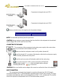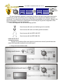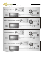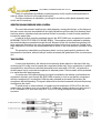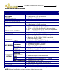
1
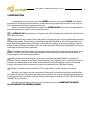
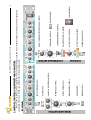
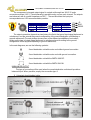
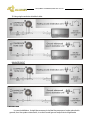
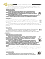
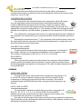
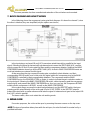
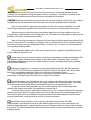
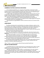
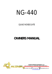
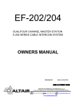
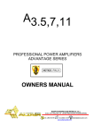
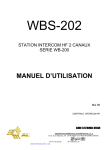
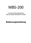
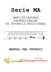
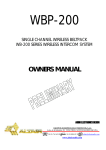
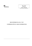
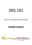
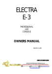
CN-220
COMPRESSOR/NOISE GATE
OWNERS MANUAL
EQUIPOS EUROPEOS ELECTRÓNICOS, S.A.L
Avda. de la Industria, 50. 28760 TRES CANTOS-MADRID (SPAIN).
34-1-804 32 65
34-1-804 43 58
[email protected]
www.altairaudio.com
DUAL/STEREO COMPRESSOR/NOISE GATE CN-220
2
1. INTRODUCTION........................................................................................................................................................................3
2. SWITCHES, CONTROLS, ADJUSTMENTS AND CONNECTORS..........................................................................................4
FRONT PANEL..........................................................................................................................................................................4
REAR PANEL ............................................................................................................................................................................5
3. WORKING PRECAUTIONS......................................................................................................................................................6
4. INSTALLATION .........................................................................................................................................................................6
UNPACKING............................................................................................................................................................................6
MOUNTING .............................................................................................................................................................................6
CHANGING THE VOLTAGE AND THE FUSE ........................................................................................................................6
CONNECTING TO THE MAINS .............................................................................................................................................. 7
INPUT CONNECTION ............................................................................................................................................................. 7
UNBALANCED INPUT .........................................................................................................................................................8
BALANCED INPUT...............................................................................................................................................................9
OUTPUT CONNECTION .........................................................................................................................................................9
UNBALANCED OUTPUT ................................................................................................................................................... 10
BALANCED INPUT.............................................................................................................................................................. 11
GROUND LINK ....................................................................................................................................................................... 11
5. OPERATION ............................................................................................................................................................................ 12
NOISE GATE........................................................................................................................................................................... 12
TEST MONITOR SWITCH (SIDE TEST) ................................................................................................................................. 12
ACTIVITY LED’s (SHUT — OPEN)......................................................................................................................................... 13
HP AND LP KEY FILTER CONTROLS................................................................................................................................... 13
THRESHOLD CONTROL..................................................................................................................................................... 13
ATTACK TIME SWITCH ...................................................................................................................................................... 13
RELEASE TIME CONTROL................................................................................................................................................... 14
RANGE SWITCH ................................................................................................................................................................ 14
BYPASS SWITCH................................................................................................................................................................ 14
COMPRESSOR....................................................................................................................................................................... 14
BAND COMPRESSOR CONTROL AND SWITCH ............................................................................................................... 14
THRESHOLD CONTROL..................................................................................................................................................... 14
COMPRESSION RATIO CONTROL..................................................................................................................................... 15
GAIN REDUCTION VUMETER ........................................................................................................................................... 15
BYPASS SWITCH................................................................................................................................................................ 15
COMMON.............................................................................................................................................................................. 15
OUTPUT LEVEL CONTROL................................................................................................................................................. 15
OUTPUT LEVEL VU-METER................................................................................................................................................ 15
STEREO SWITCH ................................................................................................................................................................ 16
SIDE CHAIN CONNECTOR................................................................................................................................................ 16
6. OPTIONS................................................................................................................................................................................. 16
SECURITY COVER (TP-1) ....................................................................................................................................................... 16
KEY LOCKED SECURITY COVER (TS-1)................................................................................................................................ 16
7. BLOCK DIAGRAM AND HOW IT WORKS............................................................................................................................17
8. REPAIR GUIDE .........................................................................................................................................................................17
9. APPLICATION EXAMPLES ..................................................................................................................................................... 19
SUPPRESSING CROSSTALK IN MULTI-MIC APPLICATIONS ........................................................................................... 19
GATING DRUMS................................................................................................................................................................... 19
REDUCING BACKGROUND NOISE..................................................................................................................................... 19
REDUCING FEEDBACK IN MICROPHONES WITH HIGH COMPRESSION .....................................................................20
LEVEL VARIATIONS IN VOICES AND INSTRUMENTS .......................................................................................................20
RECORDINGS ........................................................................................................................................................................20
SPEAKER PROTECTION ........................................................................................................................................................20
PRODUCING THE TALKOVER EFFECT................................................................................................................................. 21
INCREASING THE OUTPUT LEVEL OF A MIXING SIGNAL ................................................................................................. 21
SOUND PRESSURE LEVEL CONTROL................................................................................................................................... 21
SELECTIVE SOUND PRESSURE LEVEL CONTROL...............................................................................................................22
TIME CONTROL .....................................................................................................................................................................22
10. TECHNICAL SPECIFICATIONS .............................................................................................................................................23
11. WARRANTY............................................................................................................................................................................24
DUAL/STEREO COMPRESSOR/NOISE GATE CN-220
1. INTRODUCTION
Congratulations on your purchase of the ALTAIR compressor/noise gate CN-220. Our dilated
experience in the design and manufacture of effect processing equipment, had led to us to carry out
this compressor/noise gate of great performances.
There is a lot the characteristics that make of the ALTAIR CN-220, one of the most highlighted of
the audio professional market, here enumerated some:
The ALTAIR CN-220 incorporates in a compact unit, a Dual Compressor-Limiter with a full-featured
Noise Gate front end.
Dedicated filters are provided in the Gate section to Trigger the gate, only by the desired instrument,
avoiding false gating. Test monitoring of the filtered signal is available to set-up the gate effect. Front
panel Attack and Release time parameters are provided for optimal sound reconstruction or special
effects creations. Background stage noises are easily removed without signal degradation, enhancing
instrument control and mixing operation.
Special attention has been taken to provide the professionals with a general purpose device. Specs
such as +24 dBu (max) Input/Output level operation and extremely low output noise guarantee a
broad range of audio industry applications.
Additional features include a Band Compressor mode with adjustable frequency selection to
achieve a variety of effects as De-Essing, Vocal Stopping, Drum Levelling, etc by compressing only the
desired band without altering the whole audio spectrum. Electric Bass guitar sounds, for example,
become more natural as the harmonic contents are unaltered when “Slap Bass” playing.
Full specs, full features take the Altair CN-220 a step further in Audio Dynamic Processing.
Naturally, you want to use your compressor/noise gate, but before beginning is important that
you read this manual. This manual will help you to install and use your new compressor/noise gate. It
is very important that you read it carefully, mainly the paragraphs marked as NOTE, PRECAUTION and
DANGER, for your security.
Save the original packing, you can re-use it to transport the unit. NEVER SHIP THE ALTAIR
CN-220 WITHOUT IT'S ORIGINAL PACKING.
3
NOISE GATE SECTION
FRONT PANEL
BYPASS SWITCH.
RANGE SWITCH.
RELEASE TIME CONTROL.
ATTACK TIME SWITCH.
THRESHOLD CONTROL.
HP AND LP KEY FILTER CONTROLS.
ACTIVITY LED’s.
TEST MONITOR SWITCH.
STEREO/DUAL SWITCH.
OUTPUT LEVEL VU-METER.
OUTPUT LEVEL CONTROL.
GAIN REDUCTION VU-METER.
COMPRESSION RATIO CONTROL.
THRESHOLD CONTROL.
4
POWER SWITCH.
BYPASS SWITCH.
BAND COMPRESSOR CONTROL AND SWITCH.
These are the switches, controls, adjustments and connectors that you could find in your ALTAIR compressor/noise gate. The description and
explanation of each one of them, you will find in the corresponding section.
2. SWITCHES, CONTROLS, ADJUSTMENTS AND CONNECTORS
DUAL/STEREO COMPRESSOR/NOISE GATE CN-220
COMPRESSOR SECTION
COMMON
REAR PANEL
INPUT SIGNAL CONNECTORS, XLR-3-31 AND JACK ¼”.
SIDE CHAIN CONNECTOR, JACK ¼”.
OUTPUT SIGNAL CONNECTORS, XLR-3-32 AND JACK ¼”.
EARTH LINK SWITCH.
MAINS CONNECTOR, FUSE HOLDER AND VOLTAGE SELECTOR.
DUAL/STEREO COMPRESSOR/NOISE GATE CN-220
5
DUAL/STEREO COMPRESSOR/NOISE GATE CN-220
6
3. WORKING PRECAUTIONS
The manufacturer is not responsible of any damage occurred in the compressor/noise gate unit
outside the limits of the warranty or those produced by not keeping in mind the working precautions.
Mains voltage must be correct and the same as that setting on the rear of the unit voltage
switch. Damage caused by connection to improper AC voltage is not covered by any
warranty.
DANGER: Inside the unit there are high voltages, doesn't open it. The unit doesn't
contain elements that could be repaired by the user. Whenever the compressor/noise
gate unit is connected to the mains, contains elements with high voltages. In order to
disconnect the unit completely, you must disconnect it of the mains.
CAUTION: Protect the compressor/noise gate from the rain and moisture. Ensure that
no objects or liquids enter it. If liquid is spilled into the unit, disconnect it from the mains
and consult a qualified service technician.
Don't place the unit close to heat sources.
4. INSTALLATION
UNPACKING
Before leaving from factory, each compressor/noise gate was carefully inspected and tested.
Unpack and inspect the unit for any damage that may have occurred during shipment. If any
damage is found, doesn't connect the unit to the mains, notify the salesperson immediately,
because a qualified service technician must inspect the unit.
Save the original packing, you could use if you need to transport the unit. NEVER SHIP THE
COMPRESSOR/NOISE GATE WITHOUT IT'S ORIGINAL PACKING.
MOUNTING
It is always advisable to mount the unit in rack, either for mobile or fixed installations, for
protection, safety, aesthetics, etc.
The ALTAIR CN-220 is designed for standard 19" rack mounting, and occupy 1u high rack
space.
CHANGING THE VOLTAGE AND THE FUSE
The compressor/noise gate unit is set to operate at 230V, 50-60Hz and at 115V, 50-60Hz.
Make sure that the unit is disconnected of the mains.
In the unit rear panel, is placed the mains connector, the mains selector and the fuse holder.
The box bellow this mains connector is called fuse holder + mains selector. Take out the fuse
holder + mains selector.
Upon extracting the fuse holder, the fuse will appear, take out it and change for the new one.
Insert the fuse holder into the mains connector again, without spin it (make sure that the
voltage to which it is going to connect the unit remains indicated in normal position, not inverted), if
you only wants to change the fuse. If what you want are change the mains voltage, rotate the
fuseholder until remains the mains voltage to which it is going to connect the unit in normal
position, not inverted.
DUAL/STEREO COMPRESSOR/NOISE GATE CN-220
Compressor/noise gate set up to 115 V.
Compressor/noise gate set up to 230 V.
Make sure that the fuse is the right one for the selected voltage:
FUSE (230V. 50-60 Hz)
T0,5A.
FUSE (115V. 50-60 Hz)
T1A.
NOTE: The fuseholder provide a place for spare fuse.
CAUTION: Always make sure upon changing the fuse, that this is the adequate for the selected
mains voltage (T1A for 115V and T0,5A for 230V).
CONNECTING TO THE MAINS
The connection of the compressor/noise gate power supply to the mains takes
place by a standard cord included in the box.
Make sure that the unit power switch is at 0 position (turned off).
Insert the female I.E.C. connector of the tripolar cable into the unit power supply
male connector, placed at the rear panel.
Insert the male connector of the tripolar cable into the mains plug.
Turn on the unit power switch. In that moment the ACTIVITY LED
indicator (red or green)
of the noise gate section will light,
indicating that the unit
is turned on.
CAUTION: Make sure that the mains voltage is the correct as well as their fuse is the adequate.
INPUT CONNECTION
The compressor/noise gate input signals is carried out through two XLR-3-31 female
connectors and two JACK ¼” wired internally in parallel mode, one per each channel. The input
connections are balanced, with a nominal impedance of 10 KΩ (5 KΩ unbalanced). The next list
shows the input pins correspondence as A.E.S recommendation practice:
7
8
DUAL/STEREO COMPRESSOR/NOISE GATE CN-220
XLR-3-31
0V
PIN 1
PIN 2
HOT (+)
COLD (-)
PIN 3
JACK ¼”
TIP
HOT (+)
COLD (-)
RING
0V
SLEEVE
TIP.
RING.
SLEEVE.
The input connection depends on two factors, the first is the type of input signal balanced or
unbalanced, and the second the ground configuration of the sound source (floating or groundreferenced). The next pictures shows some of the different possibilities of connection, relying on the
type of input signal, balanced or unbalanced and according to the ground configuration of the
equipment (floating or ground-referenced).
In the next diagrams, we use the following symbols:
Sound source with mains cord without ground connection.
Sound source with mains cord with ground connection.
Sound source with the EARTH-LINK OFF.
Sound source with the EARTH LINK ON.
UNBALANCED INPUT
This type of connection will be used when the sound source doesn't provide balanced
output. When possible, employ the connection type 1.
1) Using twin-lead shielded cable:
DUAL/STEREO COMPRESSOR/NOISE GATE CN-220
2) Using single conductor shielded cable:
BALANCED INPUT
OUTPUT CONNECTION
9
10
DUAL/STEREO COMPRESSOR/NOISE GATE CN-220
The compressor/noise gate output signal is carried out through two XLR-3-32 male
connectors and two JACK ¼” wired internally in parallel mode, one per each channel. The outputs
are balanced, with a nominal impedance of 100 Ω. The next list shows the input pins
correspondence as A.E.S recommendation practice:
XLR-3-32
0V
PIN 1
PIN 2
HOT (+)
COLD (-)
PIN 3
JACK ¼”
TIP
HOT (+)
COLD (-)
RING
0V
SLEEVE
TIP.
RING.
SLEEVE.
The output connection depends on two factors, the first is the type of input signal balanced or
unbalanced, and the second the ground configuration of the sound destination unit (floating or
ground-referenced). The next pictures shows some of the different possibilities of connection,
relying on the type of output signal, balanced or unbalanced and according to the ground
configuration of the equipment (floating or ground-referenced).
In the next diagrams, we use the following symbols:
Sound destination unit with mains cord without ground connection.
Sound destination unit with mains cord with ground connection.
Sound destination unit with the EARTH-LINK OFF.
Sound destination unit with the EARTH LINK ON.
UNBALANCED OUTPUT
This type of connection will be used when the sound destination unit doesn't provide a
balanced input. When possible, employ the connection type 1.
1) Using twin-lead shielded cable:
DUAL/STEREO COMPRESSOR/NOISE GATE CN-220
2) Using single conductor shielded cable:
BALANCED INPUT
GROUND LINK
In some installations, it might be necessary to isolate the compressor/noise gate electric
ground, from the system mains earth, in order to avoid ground loops that could generate
11
DUAL/STEREO COMPRESSOR/NOISE GATE CN-220
12
unwanted noises. For this reason, the unit provides an EARTH-LINK switch placed at the rear panel
in order to lift the mains earth from the unit.
MAINS EARTH LINKED WITH THE COMPRESSOR/NOISE GATE
ELECTRIC GROUND.
MAINS EARTH LIFTED FROM THE COMPRESSOR/NOISE GATE
ELECTRIC GROUND.
NOTE: For security reasons, the earth connection to the mains is linked with the unit chassis in both
cases.
CAUTION: Always operate the unit with the AC ground wire connected to the
electrical system ground. Precautions should be taken so that the means of
grounding of a piece of equipment is not defeated. For this circumstance, NEVER
lift the mains earth AC ground to avoid possible accidents. For your security, NEVER
use ground isolator adapters; instead it is recommended the EARTH -LINK switch.
5. OPERATION
The dynamic range of an audio equipment is limited by the maximum signal level that the
audio equipment can drain without audible distortion and the noise generated by this audio
equipment.
The noise, is generated by the audio equipment because of the current flowing the conductors,
due to the random electron movements. For statistical reasons, this produces frequencies within the
whole audio spectrum. This noise is called white noise. If this noise is then strongly amplified, a noise
will be obtained perfectly audible.
The maximum signal level of the audio equipment is limited by the levels of the internal
operating voltages. If the signal exceeded the internal operating voltages, audible signal distortion is
the result. In practice, this limitation is greater, since a certain reserve must be maintained to avoid
distortion of the audio signal if sudden level peak occur. In technical words, we refer to this reserve as
“headroom”. If we reduce the input signal level, we reduce the risk of signal distortion due to level
peeks, however, at the same time, the noise floor level will be increased if we want obtain the same
output signal level, since, we must amplify more.
The compressor/limiter act as automatic gain controls, decreasing the signal level above a
certain level (THRESHOLD), restricting the dynamic range and allowing us increase the audio
equipment headroom, without decrease the input signal level. The difference between a compressor
and a limiter, is that limiters abruptly limit the signal above the threshold while the compressors will
decrease the signal level above the threshold, depend on the compression ratio set up and the ratio
of the input signal level and the threshold, it’s to say, gradually.
How we explained previously, the noise limits the audio equipment dynamic range. The noise
gates decrease the signal gain abruptly bellow the threshold allowing increase the audio equipment
dynamic range, achieving the inverse function of a compressor/limiter.
The ALTAIR CN-220 incorporates a dual Compressor-Limiter with a full-featured Noise Gate
connected internally.
NOISE GATE
TEST MONITOR SWITCH (SIDE TEST)
DUAL/STEREO COMPRESSOR/NOISE GATE CN-220
13
The side test switch, allow monitor the output signal obtained after the key filters to
set up by ear the signal that we want to open the noise gate. It is a push button,
because of that upon releasing it, the noise gate will return to its normal state.
This switch will be used only during the sound check since it disables the compressor and
noise gate effect.
NOTE: The SIDE TEST switch, connect directly the key filters output with the unit output. Therefore,
disable the compressor section, and the noise gate BYPASS switch.
STEREO: In stereo mode at the channel 2, this switch monitor the output signal obtained after
the channel 2 key filters, but the noise gate trigger with the signal obtained of the channel 1 and
channel 2 key filters average.
ACTIVITY LED’s (SHUT — OPEN)
The activity LED’s show the noise gate operation. The SHUT red LED indicate that
the key filters signal level output, which trigger the noise gate, is bellow the threshold set
up. The other OPEN green LED report that the key filters signal level output, which trigger the
noise gate, is above the threshold set up.
If the BYPASS switch is not depressed, when the SHUT red LED light, the noise gate will be
decreasing the input signal gain, and when the OPEN green LED light, the signal will pass
unchanged through the noise gate.
STEREO: In stereo mode, the channel 2 activity LED’s, won’t indicate the channel 2 noise gate
operation. The channel 1 activity LED’s will indicate the operation of both noise gates.
HP AND LP KEY FILTER CONTROLS
The lateral filters, filter the signal that will arrive to the noise gate
detector, allowing to trigger the noise gate only with the desired instrument,
or with the wanted bandwidth, avoiding false gating.
The high pass filter (HP) can vary between 30 Hz to 4 KHz, and the low
pass filter can vary between 200 Hz and 20 KHz, allowing an adjustment in all the audible
band
STEREO: Like starting point, it is convenient adjust both filters of both channels (channel 1 and 2)
with the same settings since the control on both channels is obtained by the two signals trigger
average.
THRESHOLD CONTROL
The threshold control allows set up the level above the signal will pass
unchanged through the noise gate. If the level is bellow this threshold, the noise
gate will be decreasing the input signal gain.
The threshold control can vary between —50 and +20 dBu.
ATTACK TIME SWITCH
The noise gate attack time is defined, as the delay in the noise gate opening (allow
to pass the signal unchanged) when a signal rise above the threshold level set up.
With the ATTACK switch depressed, the noise gate attack time will be configured in
AUTO mode. In this mode, the noise gate detector adapts the attack time to the input program
content, allowing an easy and quick noise gate adjustment on the part of the user.
DUAL/STEREO COMPRESSOR/NOISE GATE CN-220
14
With the ATTACK switch pressed, the noise gate attack time will be configured in FAST
mode. In this mode, the attack time is very fast, saving the signal rise edge. Therefore, in this
mode the noise gate adjustment is more difficult.
RELEASE TIME CONTROL
The noise gate hold time is defined as the delay in the noise gate closing
(decreasing the input signal gain) when a signal drop the threshold level set up.
The release time begins after the hold time, and ends when the gain reduction
adjusted with the RANGE switch is achieved.
The release time control adjust the noise gate release time between 10 msg and 2 sg,
and at the same time set up a hold time according with the release time adjustment.
RANGE SWITCH
The range switch determines the amount of gain reduction produced in the
program signal when the noise gate is close. With this switch depressed, the program
gain reduction will be 80 dB, and with this switch pressed, the program gain reduction
will be 20 dB.
In most of the applications, it is preferable use the 20 dB range, that although it don't
produce a total gate, and introduce less adverse effects when signals with much noise floor are
processed.
BYPASS SWITCH
When we press this noise gate bypass switch, the noise gate will be disabled and
the controls and switched won’t be operative. The activity LED’s continue working
indicating our set up, but the program signal will pass unchanged through the noise gate.
COMPRESSOR
BAND COMPRESSOR CONTROL AND SWITCH
When the band compressor is active, it’s to say, with the ON switch pressed,
the compressor stops compressing in the whole audio spectrum, in order to only
compress in the selected band. With the ON switch depresses, the compressor
work normally (in the whole audio spectrum).
The band compressor control, allow to configure the selected band from 80
Hz to 10 KHz. Configured the band compressor control between 5 KHz and 10 KHz
works like DE-ESSER, it allow to reduce notably the sibilance effect that takes place with the
treatment of vocals with a great content in high frequencies, mainly with the letter "s."
In band compressor mode, the compression ratio and the threshold adjusts continues
working.
STEREO: In stereo mode, any of the ON switches will put both compressors in band compressor
mode, however, the band compressor control will be independent in both channels, for that if
you want that the band compressors work symmetrical, both controls will placed at the same
position.
THRESHOLD CONTROL
The threshold control sets the level where compression will begin. The
signals below the level defined at the threshold control will pass unchanged and
DUAL/STEREO COMPRESSOR/NOISE GATE CN-220
15
the signals above the level defined at the threshold control will be compressed in
correspondence with the compression ratio control adjustment. The threshold range control
varies from -40 to +20 dBu.
COMPRESSION RATIO CONTROL
The compression ratio controls the amount of compression, which will happen
once the input signal crosses the threshold level. Its adjustment determines the
number of dB that the input signal should increase, in order to increase a dB the
output signal, whenever the input signal cross the threshold level. For example, if we
adjusted the compression ratio control to 4: 1, the variation of 4 dB in the input signal will be
reflected in the output as only 1 dB variation. A variation of 8 dB, will produce 2 dB of variation,
etc.
If we adjusted the compression ratio control to 1: 1, the input signal won't be modified for
the compressor, for what we will have a compressor BYPASS, and the threshold control won't
affect.
Adjusting the compression ratio to ∞:1, the compressor will work like a limiter, that to say,
the output signal will never overcome the threshold level adjustment, no matter how much
above the threshold the input signal goes.
GAIN REDUCTION VUMETER
The gain reduction produced by the input signal compression, it is indicated in
this vumeter, allowing us in all moment the visualisation of the compressor action.
This vumeter is composed by 8 LED’s (30, 20, 15, 12, 9, 6, 4 and 2 dB).
BYPASS SWITCH
When we press this compressor bypass switch, the compressor will be disabled
and the controls and switched won’t be operative. The gain reduction vumeter will turn
off indicating that the input signal is not compressed. This switch is totally independent of the
noise gate BYPASS.
COMMON
OUTPUT LEVEL CONTROL
The output level control, allow to attenuate or amplify the output signal of- 15
to +15 dB. This control is useful for making up gain which was reduced by the
compression or matching the input level of a mixer or recorder. This control is
enabled although the BYPASS switches of the noise gate and the compressor are
pressed
OUTPUT LEVEL VU-METER
The output level is indicated constantly by this vu-meter, compound for 12
LED's (30,- 20,- 12,- 8,- 4,- 2, 0, 2, 4, 8, 12 and 16 dB). The red 16 dB LED
indicates that we have a high level in the output, however, to this level the unit
is not saturated still, since it has a "headroom" of 5 dB.
If we want to know the signal input level, we will press the noise gate and compressor
BYPASS switches and we will locate the output level control to 0 dB (centered), and this vu-meter
will indicate us directly the input level.
DUAL/STEREO COMPRESSOR/NOISE GATE CN-220
16
CAUTION: In Band Compressor mode, the headroom is more limited for what it is not advisable
overcome the 16 dB of output level when we operate with negative adjustment of the output
level control.
STEREO SWITCH
The stereo switch, allow us to select the unit working mode. With this switch
depressed, the unit operation mode is DUAL, this permit us the treatment of two
independent signals, adjusting each noise gates and compressor of independent
mode. Upon pressing the switch, the channel 2 will be slave of the channel 1, for what the
controls of the channel 2 will be disabled (except for the cases specified with the STEREO note:
TEST MONITOR SWITCH, ACTIVITY LED’s, HP AND LP KEY FILTER CONTROLS and BAND
COMPRESSOR SWITCH AND CONTROL, explained each one in their corresponding section).
NOTE: In STEREO mode the signal that arrives to the noise gate and compressor detectors, is an
average of the two input signals.
SIDE CHAIN CONNECTOR
In the noise gate and compressor normal operation, the input signal is
used for the noise gate and compressor detector in order to carry out the noise
gate triggers and compress the same input signal. This ¼” stereo JACK
connector allow to use another signal (or the same input signal processed) in
order to trigger the noise gate and compress the input signal according to the adjusted
parameters.
In order to introduce a signal different from the input signal, we will use a ¼” mono JACK ,
with the signal in the tip.
If we want to process (equalise, expand, level change, etc.) the input signal, we will
connect a ¼” stereo JACK , and we will obtain the input signal the ring, and we will return to the
unit for the tip.
The external control JACK connector input and output are unbalanced.
The input impedance is 10 KΩ, and the output impedance is 220 Ω. The input and output
SIDE CHAIN nominal level is - 3 dB.
NOTE: In the Band Compressor mode, the external control is disabled.
6. OPTIONS
In this section will explain the different available options for the unit.
SECURITY COVER (TP-1)
In some installation, it could be necessary to tamper proof the front panel controls avoiding
unwanted or accidental manipulations. For this purpose, it is available as an option, a transparent
plastic security cover. The installation is very easy, by means of two screws provided.
KEY LOCKED SECURITY COVER (TS-1)
In some installations it is necessary isolate the compressor/noise gate controls more
securely than with the plastic security cover. For this extra protection, it is available an all-metallic
and lockable security cover. This option cover fits into the four rack holes of the unit and includes
rear nut-bars allowing the installation as a stand-alone unit.
DUAL/STEREO COMPRESSOR/NOISE GATE CN-220
17
This cover prevents also from unauthorised extraction of the unit when rack mounted.
7. BLOCK DIAGRAM AND HOW IT WORKS
In the following shows the compressor/noise gate block diagram. It is draw the channel 1, since
the other is identical, they are simplified (only the options are shown)
In the input stage, we have XLR and JACK connectors wired internally in parallel for the input
signal. Following the signal is electronically unbalanced and crosses the SIDE CHAIN JACK, next the
signal crosses the HP and LP noise gate key filters and the compressor detector. Note that the BAND
COMPRESSOR detector doesn't go by the SIDE CHAIN JACK, for that in BAND COMPRESSOR mode we
could not introduce an external control signal.
At the same time the sign crosses the noise gate, controlled by their detector, and their
corresponding BYPASS switch, and in this point, the signal split to the compressor and to the BAND
COMPRESSOR, controlled by their corresponding detectors. The compressor and the BAND
COMPRESSOR act on the GAIN REDUCTION vu-meter, in order to indicate the gain reduction made on
the input signal. Following the BAND COMPRESSOR ON switch, without pressing gets the compressor
output signal, and pressed the BAND COMPRESSOR one. How you can see, the compressor BYPASS
switch puts the compressor in BYPASS, as well as the BAND COMPRESSOR.
In the output stage, we were the output level adjustment, and the SIDE TEST switch, that upon
pressing get the output directly of the noise gate HP and LP KEY FILTERS. In the SIDE TEST output is
gotten the output level vu-meter reference and later the signal is balanced and goes to the output XLR
and JACK, wired in parallel.
The stereo switch, allow us to select the unit working mode.
8. REPAIR GUIDE
For service purposes, the unit must be open by removing the seven screws on the top cover.
NOTE: This type of operations takes place with the unit open, for what it should be carried out by a
qualified technician.
DUAL/STEREO COMPRESSOR/NOISE GATE CN-220
18
DANGER: Before opening the unit, disconnect it from the mains. It is important to indicate that
although the unit is power out (with the power switch in 0 position), if it continues connected to the
mains there are different parts of the unit that are subjected to high voltage.
CAUTION: Protect the compressor/noise gate from the rain and moisture, mainly if it is open. If liquid
is spilled into the unit, disconnect it from the mains and consult a qualified service technician.
Keep in mind that both outputs are symmetrical, so when the section is identified, you could
interchange components, except for the circuits that are common as could be the power supply.
We recommend a meticulous visual exam before beginning to change anything in the unit:
burnt resistors, potentiometers with a broken trace, etc. This exam many times gives us the key for the
problem, saving time and unnecessary efforts.
Keep in mind when removing an element of the main board, that it is single layer printed circuit,
and the components PADs could get up if applies them an excessive heat. This is important mainly in
components having many pins (integrated circuits, connectors, etc.), for which it is recommended to
use a good desoldering station.
Next paragraphs details some of the most frequent fixes as a guide to the qualified technical
service helping to repair the unit:
If a fuse break due to a mains transient or when the unit has been connected accidentally to 380
line voltages, replace it with the same ratings as described before. If it breaks again, check the
overvoltage protections placed on the voltage selector. If broken, substitute them by an equivalent
part (130 volts VARISTOR).
If the power supply fails, it is necessary to check the rectifier bridge (D13), the filter capacitors
(C55, C56, C57 and C58) and the regulators (U31 and U32). Keep in mind that if the unit has been
turned on, the regulators heatsinks could be hot, with the rising danger of burns.
Upon changing the damaged element, it is necessary to ascertain that no element is
overheating in the main board, since this can be origin of the problem.
The potentiometers have a limited live span; they could become dirty and produce noise upon
moving them. It is important that you don't use sprays cleaners over the potentiometers, since they
can become damaged shortly. We recommended cleaning it by compressed air only.
In order to change a potentiometer, the unit must be opened. Care must be taken when
removing the bottom cover as the line transformer is attached to it.
To remove the front panel, extract all five visible screws. The sub-panel behind the front panel is
joined to the chassis by four screws located in the chassis sides and by the potentiometers. Special
care must be taken when re-install the front panel because some delicate parts as the LED lamps
must be introduced in small panel holes and it is a not easy operation.
Normally the signal reductions in the unit are produced by three causes: the LEVEL
potentiometers, the unbalanced circuit and the electronic balanced one. In the unbalanced and
electronic balanced circuits, a signal reduction around 6 dB reveals that one halves of the circuit has
any trouble. The LEVEL potentiometers failures gives also sudden random signal reductions as well as
swinging signals.
DUAL/STEREO COMPRESSOR/NOISE GATE CN-220
19
9. APPLICATION EXAMPLES
SUPPRESSING CROSSTALK IN MULTI-MIC APPLICATIONS
The most frequent application of a noise gate is the elimination of unwanted crosstalk
between microphones during recording and playback, mainly in the drum sounds, because here
several microphones closely positioned next to each other. By this reason it is desirable to gate
each microphone in order to avoid the crosstalk in adjacent microphones.
In order to begin, it is important the microphones placement, so that they capture the minor
possible signal of the adjacent instruments. Once placed, adjust the noise gate HP and LP KEY
FILTERS, so that the noise gate is only triggered with the sound of the instrument that we want to
gate. Use the SIDE TEST function to monitor the signal that will trigger the noise gate.
Adjust the noise gate THRESHOLD, so that the threshold level remain lower than the
minimum signal produced by the instrument, and higher than the crosstalk signals of the adjacent
instruments (this maybe is the most delicate step).
Lastly, adjust the noise gate RELEASE, so that the instrument overall sound character will be
retained.
GATING DRUMS
“The difference between rally musically effective drum gating and disastrous gating is a fine
line. Ambience, crash cymbals, resonating skins and snare and hi-hat bleed are among the most
common pests when recording acoustic drums. The following tips may help you elude any of
these bleed problems and allow all drum effects or equalisers to receive the cleanest of
uninterrupted, natural drum sounds. With this application, we will be used the two channels of the
noise gate and two channels of the mixer console.
For key mic, routing and patched, gated signal.
Step 1: Set up two microphones on the snare, one underneath, almost touching the snares
(key mic), your second microphone normally positioned one to four inches away above the snare
(snare mic).
Step 2: Set up gate getting on snare mic, not choking signal with too much threshold.
Step 3: Solo key mic input; set up gate on key mic with fast release, fast attack, tightest
possible threshold (you’ll just hear a tick with snare contact) and maximum range (80 dB).
Step 4: At this point you must patch output of gated key mic signal to the SIDE CHAIN input on
snare mic gate, so that the key mic gate trigger the snare mic gate.
This method of gating will completely separate snare, tom and kick signals without injuring in
any way the natural sound qualities of each of these drums, therefore allowing effects and
equalisers to receive the cleanest possible send.”
Stacey T. Heydon — producer/engineer (Sheriff #1 single), guitarist (David Bowie).
REDUCING BACKGROUND NOISE
In applications that have a high background noise: recording plate noise, guitars and bass
amplifiers noise, broadcast applications with a wide auditory and multiple microphones, etc.,
could be eliminated with the noise gate.
Adjust the noise gate HP and LP KEY FILTERS, in vocal applications in the voice frequency
range, in applications with bass or guitar covers the instrument bandwidth, in full range
applications leave the filters full range, so that the noise gate is only triggered with the sound of the
instrument that we want to gate. Use the SIDE TEST function to monitor the signal that will trigger
the noise gate.
DUAL/STEREO COMPRESSOR/NOISE GATE CN-220
20
Adjust the noise gate THRESHOLD, so that the threshold level remain lower than the
minimum signal produced by the instrument, and higher than the noise background signals (this
maybe is the most delicate step).
Lastly, adjust the noise gate RELEASE, so that the instrument overall sound character will be
retained.
REDUCING FEEDBACK IN MICROPHONES WITH HIGH COMPRESSION
In stage microphones, for voice treatment, if the signal is high compressed, upon taking
place a pause in the signal, the compressor automatically increases their gain (upon falling the
signal below the compression threshold, it stop compressing the signal), and it could give rise to
feedbacks.
The noise gate could be used in order to eliminate these feedbacks. Upon introducing the
noise gate in the signal path, if a pause in the sign takes place and falls below the noise gate
threshold, the noise gate will reduce the gain compensating the increase of gain due to the
compressor, for what the feedback won't take place.
With the attack time switch in AUTO and the range switch in 80 dB (it could use configured to
20 dB if you are wanted to simplify the adjustment), adjust the noise gate threshold, so that mute
the microphone when the signal pauses take place (this maybe is the most delicate step).
Lastly, adjust the noise gate RELEASE, so that the overall sound character will be retained.
LEVEL VARIATIONS IN VOICES AND INSTRUMENTS
When there is a variation in the distance between the singer or vocalist and the microphone, a
change in the signal level takes place. This effect could be reduced with the compressor/ limiter:
Adjust the compression ratio between 2:1 and 4:1 and immediately adjust the compression
threshold until a good result is reached. If necessary, it is possible to vary the compression ratio
again.
From the same way, it is possible to regulate the instruments level variations, being able to
maintain present the bass sound and stabilising the level changes in the jack level in several
keyboards. Adjust the compression ratio, like in the previous case, between 2:1 and 4:1, and the
compression threshold until obtain the wanted result. The compression will produce us a sonority
decrease produced by the variations between the instrument cords, increasing the notes
maintenance and reducing the excess of sibilance.
RECORDINGS
During the recordings, the compressor/limiter adapts the program dynamic margin to the
support used, if the program has a dynamic margin of 100 dB, and the recording support has a
dynamic margin of 80 dB, it will be necessary to reduce the program dynamic margin to 80 dB. For
this application, adjust the compression ratio to 2:1, and adjust the compression threshold so that
the program strongest signal produces a gain reduction of 15 or 20 dB. Lastly, adjust the output
level in order to obtain 0 dBu at the recording unit. If adjust the unit like limiter, it cancel the peaks
to avoid the band saturation.
SPEAKER PROTECTION
The compressor/ limiter is largely used to prevent possible breaks-downs in the speakers, due
to abusive manipulations and certain negligences such as break of cables, falling of mics, etc. The
compressor/ limiter improves the intelligibility of the speakers, since it allows that low level signals
are reproduced by the system with the maximum amplification.
DUAL/STEREO COMPRESSOR/NOISE GATE CN-220
21
The compressor/limiter adjustment for this application depends on the speakers system
characteristics, but in circumstances in which the break risk of the speakers increases, many
technicians adjust the compression ratio to ∞:1, that is to say adjusted like limiter, depending the
compression threshold adjustment on the speaker system characteristics.
PRODUCING THE TALKOVER EFFECT
To produce the talkover effect in the signal, all we have to do is to introduce part of the voice
signal (or channel line output) that we want to project from the general level, into the compressor
SIDE CHAIN input. When the signal introduced into the INSERT input surpass the compression
threshold, the program signal level will descend automatically. Of course, if we don't want the voice
affected by this compression, it should not be introduced into the compressor. This is easily achieved
using SUBGROUPS.
INCREASING THE OUTPUT LEVEL OF A MIXING SIGNAL
It is possible to separate voices and instruments of a mix signal, by means of a frequency
compression. The way to do it is to introduce a graphic equaliser in the compressor SIDE CHAIN
input. The equaliser must equalise the programmed signal, and must introduce it in the compressor
SIDE CHAIN input, while the compressor input is connected to the program signal (of course, this has
not been equalised). The bands amplified by the equaliser will show up more compressed in the
output signal, and the output signal will not be affected by the phase changes produced by the
equaliser, once the compressor threshold is reached. Of course, the output level of the whole
program is affected when the compression takes place, and so we will have to adjust the output
level control.
SOUND PRESSURE LEVEL CONTROL
The compressor/limiter has a wide range of application in sound pressure level control of
discos and pubs in order to warrant the maximum level authorised by the local authority. With this
purpose, it is always placed in the last point of the audio chain, that is to say, before the power
amplifier, or before the active divisor if working in multi-amplification. If the hall has a graphic
equaliser, it is highly advisable to keep it out of the reach of the DJ; that is why it will be protected
with a sealed lid once the equalisation has taken place.
To adjust the compressor, connect the compressor inputs to the equaliser outputs or mixing
console and connect the outputs to the power stage inputs. Choose a recording containing a big
percussive and loud sound. Adjust the pick-up sensitivity, that channel fader and the master to the
maximum. Select the STEREO operation mode by pressing the compressor STEREO button (the RATIO,
THRESHOLD and OUTPUT controls will depend on its adjustment in the CH1 channel in both channels
for this operation mode). Adjust the RATIO control to ∞:1 if the hall is very problematic or to 8:1 if it is
not. Adjust the THRESHOLD (compression threshold) to the left until the GAIN REDUCTION indicator
indicates 15 dB in the program peaks. Adjust the OUTPUT control to -15 dB. Connect the power
amplifier/s with their gain controls to the maximum.
Now the moment has come to use a the sound pressure level measuring system, in the hall,
or in the street or behind the hall walls in the house subject to protection. Increase the OUTPUT
control by turning it to the right, until it reaches to the maximum level authorised for the sonometer in
that point. This operation is more reliable if the noises produced by the customers in the hall are
included in the measures.
If the outcomes are not entirely satisfactory, repeat every adjustment, but adjusting the
THRESHOLD until the gain reduction reaches 20 dB.
DUAL/STEREO COMPRESSOR/NOISE GATE CN-220
22
Finally, it is advisable to try different musical programs and to vary the mixer equalisation in
order to make a final touch in the output level control.
Once the compressor is adjusted to, your liking it is as well to put the plastic protection lead
and to seal it if necessary.
SELECTIVE SOUND PRESSURE LEVEL CONTROL
The sound transmission level through a body depends, among other things, on the frequency
(the low sounds are more transmitted than the high-pitched through the walls), and therefore there
are times when a selective sound pressure level control is necessary, in order to make possible to
increase the power later.
In order to do that, insert the equalised signal in the SIDE CHAIN input, as explained in section
INCREASING THE OUTPUT LEVEL OF A MIXING SIGNAL . The equaliser must be adjusted by imitating
the sound transference operation through the wall. Because of this, this transference operation has
to be measured (for instance; by using an spectrum analyser) in the room we want to "isolate" from
these frequencies. Of course, this measurement will be made in the usual pressure conditions of the
hall.
This procedure, extensible to any frequency band, can be a great resort for problems in the
transmission of structures, without having to reduce excessively the global level of the room because
of it.
TIME CONTROL
In many local legislations, the allowed sound pressure levels depend on the time of the day,
and because of it is very usual to operate the compressor/limiter only from a certain time. In order to
accomplish this, we will use an standard time switch and a relay with a 220 VAC. coil and with a
double reverse circuit, connected as explained in attached picture. The time switch will be protected
in a sealed box with legal purposes.
As can be seen in the block diagram, the signal controlled by the detector, and therefore the
compressor dynamic, pass through the SIDE CHAIN connector, in such a way that the compressor
will stop compressing if we interrupt it. With the relay activated (as showed in the picture), the
compressor will start operating. The signal cable must be short and screened, because the primary
circuit goes to the mains.
To avoid noises or mains isolations, it is better to put a transformer of 220 to 12V in the time
switch output, for instance, and use a relay of 12 V. of alternate. Another solution may be to use a 9
or 12 V. converter of DC and use a relay of DC of 9 or 12 V, being perhaps the most safe and
economic.
DUAL/STEREO COMPRESSOR/NOISE GATE CN-220
23
10. TECHNICAL SPECIFICATIONS
TECHNICAL SPECIFICATIONS
INPUTS:
INPUT IMPEDANCE:
INPUT LEVEL:
OUTPUTS:
OUTPUT IMPEDANCE:
OUTPUT LEVEL:
SIDE CHAIN INPUT/OUTPUT:
FREQUENCY RESPONSE:
DISTORTION:
INTERCHANNEL CROSSTALK:
C.M.R.R.:
OUTPUT NOISE:
•
•
•
•
•
•
•
•
•
•
•
•
•
•
•
•
OUTPUT GAIN:
GATE SECTION
FILTERS:
THRESHOLD:
ATTACK TIME:
RELEASE TIME:
RANGE:
THRESHOLD:
THRESHOLD
TRANSITION:
COMPRESSION ATTACK/RELEASE
SECTION
TIMES:
RATIO:
•
•
•
•
•
•
•
•
•
“Soft Knee” type contour.
•
Automatic: Program content dependent.
•
Variable from 1:1 (no compression) to ∞:1 (limiter).
BAND COMPRESSOR: •
MAINS SUPPLY:
POWER REQUIREMENT:
DIMENSIONS:
OPTIONS:
XLR-3-31 and JACK ¼”.
20 KΩ. Electronically balanced.
0 dBu nominal / +24 dBu maximum.
XLR-3-32 and JACK ¼”.
100Ω. Electronically balanced.
0 dBu nominal / +24 dBu maximum.
JACK ¼” unbalanced.
0 dBu nominal / +21 dBu maximum.
20 Hz to 40 KHz (+0, -0.5 dB).
THD+N < 0,03% @ 0 dBu (20 Hz- 20 KHz) no compression.
THD+N < 0,05% @ 0 dBu (1KHz) @ 20 dB compression.
IMD
< 0,03% @ 0 dBu (20 Hz- 20 KHz) no compression.
Better than 80 dB (20 Hz - 20 KHz).
Better than 60 dB (20 Hz - 20 KHz).
Better than —96 dBu, (20 Hz - 20 KHz), unweighted.
Gate section in By-pass.
Better than —98 dBu, (20 Hz - 20 KHz), unweighted.
Gate section in SHUT state.
Variable from —15 dB to +15 dB. Detent position at 0 dB.
HPF: 30 Hz — 4 KHz, LPF: 200 Hz — 20 KHz.
Variable from —50 dBu to +20 dBu.
AUTO mode: Program dependent.
FAST mode: T < 100 µsg.
Variable from 10 msg to 2 sg.
SHUT state attenuation 80 dB/20 dB.
Variable from —40 dBu to + 20 dBu.
•
•
•
•
Variable from 80 Hz to 10 KHz.
User selectable 115/230 VAC ±12%, 50-60 Hz.
30 V.A.
483x44x160 mm. (19" x 1u).
Plastic or metal (key protected) security cover.
NOTE: Technical specifications subject to variation without previous notice.
24
DUAL/STEREO COMPRESSOR/NOISE GATE CN-220
11. WARRANTY
This unit is warranted by Equipos Europeos Electrónicos to the original user, against flaws in the
manufacturing and in the materials, for a period of one year, starting from the date of sale.
Flaws due to wrong use of the unit, internal modifications or accidents, are not covered by this
warranty.
There is no other warranty expressed or implicit.
Any faulty unit must be sent, to the dealer or the manufacturer. The serial number of the unit
must be included with any request for the technical service.
Equipos Europeos Electrónicos reserves the right to modify the prices or the technical
specifications without notice.
SERIAL NUMBER
...................................................
EQUIPOS EUROPEOS ELECTRÓNICOS, S.A.L
Avda. de la Industria, 50. 28760 TRES CANTOS-MADRID (SPAIN).
34-1-804 32 65
34-1-804 43 58
www.altairaudio.com
[email protected]
25
DUAL/STEREO COMPRESSOR/NOISE GATE CN-220
European Union
Waste Electronics Information
Unión Europea
Información sobre residuos electrónicos
Waste from Electrical and Electronic Equipment (WEEE) directive
The WEEE logo signifies specific recycling programs and procedures for
electronic products in countries of the European Union. We encourage the
recycling of our products. If you have further questions about recycling, contact
your local sales office.
Directiva sobre Residuos de Aparatos Eléctricos y Electrónicos (RAEE)
El logotipo de la Directiva RAEE se refiere a los programas y procedimientos
específicos de reciclaje para aparatos electrónicos de países de la Unión
Europea. Recomendamos el reciclaje de nuestros productos. Si tiene alguna
consulta, póngase en contacto con su Distribuidor.
Information based on European Union WEEE Directive 2002/96/EC
Información basada en la Directiva de la unión europea RAEE 2002/96/EC y el Real Decreto 208/2005
AUDIO ELECTRONICS DESIGN
EQUIPOS EUROPEOS ELECTRÓNICOS, S.A.L
Avda. de la Industria, 50. 28760 TRES CANTOS-MADRID (SPAIN).
34-91-761 65 80
34-91-804 43 58
www.altairaudio.com
[email protected]